Service Manual
Page 15
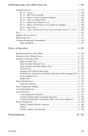
... 8 - 237 Cover Open Detection 8 - 238 Toner Detection 8 - 239 Color Registration Detection 8 - 241 Customer Replaceable Consumable Detection 8 - 242 Customer Replaceable Consumable (CRC) Life Counter Behavior ..........8 - 242 Printer Components 8 - 244 Engine Controller Board Connectors 8 - 246 Sensors...8 - 248 Clutches, Motors and Solenoids 8 - 250 Wiring Diagrams 10 - 251 Contents xiii Printer Unit Chassis (1 of 2 7 - 202 PL 5.2 - Top Cover...
... 8 - 237 Cover Open Detection 8 - 238 Toner Detection 8 - 239 Color Registration Detection 8 - 241 Customer Replaceable Consumable Detection 8 - 242 Customer Replaceable Consumable (CRC) Life Counter Behavior ..........8 - 242 Printer Components 8 - 244 Engine Controller Board Connectors 8 - 246 Sensors...8 - 248 Clutches, Motors and Solenoids 8 - 250 Wiring Diagrams 10 - 251 Contents xiii Printer Unit Chassis (1 of 2 7 - 202 PL 5.2 - Top Cover...
Service Manual
Page 40
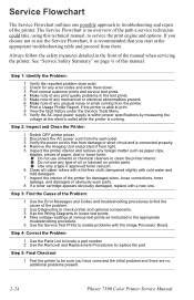
...printer...printer ...printer. 7 Print a Usage Profile Report, if the printer...printer and optional components. 3 Use the Wiring Diagrams to locate... test points. 4 Take voltage readings at the appropriate troubleshooting table and proceed from light. 5 Inspect the printer interior and remove any foreign matter such as instructed in the appropriate troubleshooting procedure. 5 Use the Service Test Prints to clean the printer... Safety Summary" on printer parts. ■ ... Test the printer to be ... the printer for ...of the printer. Step 4:...the Printer: 1 Switch OFF printer power...
...printer...printer ...printer. 7 Print a Usage Profile Report, if the printer...printer and optional components. 3 Use the Wiring Diagrams to locate... test points. 4 Take voltage readings at the appropriate troubleshooting table and proceed from light. 5 Inspect the printer interior and remove any foreign matter such as instructed in the appropriate troubleshooting procedure. 5 Use the Service Test Prints to clean the printer... Safety Summary" on printer parts. ■ ... Test the printer to be ... the printer for ...of the printer. Step 4:...the Printer: 1 Switch OFF printer power...

Service Manual
Page 41
...procedures are to the question is "No", then follow the instructions for testing parts of the printer. 4. Troubleshooting Procedures often ask you to the section "Wiring Diagrams" on page 10-251 for complete information on Troubleshooting 1. The action is to perform a certain... a momentary drop in a Troubleshooting Procedure instructs you must follow the instructions for removing and replacing all spared parts of the printer. When a troubleshooting procedure instructs you should replace the entire parent assembly. Each Step in voltage that component is receiving the ...
...procedures are to the question is "No", then follow the instructions for testing parts of the printer. 4. Troubleshooting Procedures often ask you to the section "Wiring Diagrams" on page 10-251 for complete information on Troubleshooting 1. The action is to perform a certain... a momentary drop in a Troubleshooting Procedure instructs you must follow the instructions for removing and replacing all spared parts of the printer. When a troubleshooting procedure instructs you should replace the entire parent assembly. Each Step in voltage that component is receiving the ...

Service Manual
Page 90
... to the low-voltage power supply. You may see the Engine Controller Board LED flash immediately after power-on the +5 Volt Loop wiring diagram. Replace the defective wiring harness or component and the Engine Controller Board. 2. This indicates the problem lies with the Engine Controller Board or... power-up the low-voltage power supply (LVPS) generates a +5 volt signal which is probably bad. 5. The +5 VDC Loop Refer to the wiring diagram, "The +5 Volt Loop" on page 10-258 for all wiring harnesses are operating correctly. 3-74 Phaser 7300 Color Printer Service Manual
... to the low-voltage power supply. You may see the Engine Controller Board LED flash immediately after power-on the +5 Volt Loop wiring diagram. Replace the defective wiring harness or component and the Engine Controller Board. 2. This indicates the problem lies with the Engine Controller Board or... power-up the low-voltage power supply (LVPS) generates a +5 volt signal which is probably bad. 5. The +5 VDC Loop Refer to the wiring diagram, "The +5 Volt Loop" on page 10-258 for all wiring harnesses are operating correctly. 3-74 Phaser 7300 Color Printer Service Manual

Service Manual
Page 134
...tight against the bottom of the transparency, without causing the sheet to about 12 mm (.5 in.) past the Registration Rollers A, see diagram below. To adjust the anvil, loosen the screw and slide it up to bow. Automatic Thickness Sensor (ATS) Calibration Procedure The... transparency will cause significant damage to properly calibrate the ATS Sensor, you MUST use Phaser 35-Series Premium Transparencies. Door A and manually feed a sheet of proper adjustment. 4-118 Phaser 7300 Color Printer Service Manual This procedure is set too high, media jams at registration rollers can occur...
...tight against the bottom of the transparency, without causing the sheet to about 12 mm (.5 in.) past the Registration Rollers A, see diagram below. To adjust the anvil, loosen the screw and slide it up to bow. Automatic Thickness Sensor (ATS) Calibration Procedure The... transparency will cause significant damage to properly calibrate the ATS Sensor, you MUST use Phaser 35-Series Premium Transparencies. Door A and manually feed a sheet of proper adjustment. 4-118 Phaser 7300 Color Printer Service Manual This procedure is set too high, media jams at registration rollers can occur...

Service Manual
Page 174
2 1 OPTN 19 20 SHUTTER 8 1 HOPFF F7 1 BELTHET F5 F2 F3 F4 81 JOBOFF I D 16 1 FAN 13 12 RCL 10 1 RSNS PARTTEMP 2 1 REG 15 1 2 16 1 10 1 JODEN FSENS 1 14 2 F1 91 FEED 3 COVOPN 4 TR1OP 21 GEARED 22 1 2 FCOVER FRPUCL 1 3 F6 1 5 1 DUPLEX15 5 PSIZE1 15 HVOLT 1 F8 26 POWER 2 1 6 HOPLIFT 2 16 6 2 16 2 25 1 4 1 STDUCOV S7300-158 Diagram of Engine Controller Board connectors to aid in removal. 6-158 Phaser 7300 Color Printer Service Manual
2 1 OPTN 19 20 SHUTTER 8 1 HOPFF F7 1 BELTHET F5 F2 F3 F4 81 JOBOFF I D 16 1 FAN 13 12 RCL 10 1 RSNS PARTTEMP 2 1 REG 15 1 2 16 1 10 1 JODEN FSENS 1 14 2 F1 91 FEED 3 COVOPN 4 TR1OP 21 GEARED 22 1 2 FCOVER FRPUCL 1 3 F6 1 5 1 DUPLEX15 5 PSIZE1 15 HVOLT 1 F8 26 POWER 2 1 6 HOPLIFT 2 16 6 2 16 2 25 1 4 1 STDUCOV S7300-158 Diagram of Engine Controller Board connectors to aid in removal. 6-158 Phaser 7300 Color Printer Service Manual

Service Manual
Page 251
...when the paper can not be loaded from . . . Paper size errors occur when the registration entrance sensor does not turn OFF within the printer. Paper Exit Duplex Entrance Sensor Fuser Exit Sensor Paper Tranfer MPT Entrance Sensor Transfer Belt Entrance Sensor Multi-Purpose Tray (MPT) Duplex entry Duplex...S7300-127 Theory of jam locations within a specified amount of time, meaning the jam occurs along the path of time. When a paper jam is a diagram of Operation 8-235 Paper Jam Detection The printer checks for a paper jam when the printer is powered on and during printing.
...when the paper can not be loaded from . . . Paper size errors occur when the registration entrance sensor does not turn OFF within the printer. Paper Exit Duplex Entrance Sensor Fuser Exit Sensor Paper Tranfer MPT Entrance Sensor Transfer Belt Entrance Sensor Multi-Purpose Tray (MPT) Duplex entry Duplex...S7300-127 Theory of jam locations within a specified amount of time, meaning the jam occurs along the path of time. When a paper jam is a diagram of Operation 8-235 Paper Jam Detection The printer checks for a paper jam when the printer is powered on and during printing.

Service Manual
Page 267
A" "Paper Path Sensors - Contents Description "Motors and Drum Contacts" "Power and Fans" "Paper Path Sensors - Wiring Diagrams This section contains all the wiring diagrams for the Phaser 7300 Printer. B" "Front Panel and Toner Sensor Board" "High Voltage and Low Voltage Power Supplies" "The +5 Volt Loop" Optional Duplex Unit and LTA/LTD Controller Board Page 10 - 252 10 - 253 10 - 254 10 - 255 10 - 256 10 - 257 10 - 258 10 - 259 Wiring Diagrams 10 - 251
A" "Paper Path Sensors - Contents Description "Motors and Drum Contacts" "Power and Fans" "Paper Path Sensors - Wiring Diagrams This section contains all the wiring diagrams for the Phaser 7300 Printer. B" "Front Panel and Toner Sensor Board" "High Voltage and Low Voltage Power Supplies" "The +5 Volt Loop" Optional Duplex Unit and LTA/LTD Controller Board Page 10 - 252 10 - 253 10 - 254 10 - 255 10 - 256 10 - 257 10 - 258 10 - 259 Wiring Diagrams 10 - 251

Service Manual
Page 269
... Green Black 3 1 CN5 2121 31 CN9 CN10 CN8 2. SIDETHRMSTR 18. COM(0V) 12. RPSFANERROR Red Black White Black " Rear Power Supply Fan S7300-177 Wiring Diagrams 10 - 253 CCAGEFANERROR 2. GND 8. COM(0V) 12. +34V 13. +34V 14. +34V 15. +12V 16. MIDFUSFANERROR 6. OFFSETSOLR 3. COM(3.8V) Red Rear Fuser Fan Top Fuser...
... Green Black 3 1 CN5 2121 31 CN9 CN10 CN8 2. SIDETHRMSTR 18. COM(0V) 12. RPSFANERROR Red Black White Black " Rear Power Supply Fan S7300-177 Wiring Diagrams 10 - 253 CCAGEFANERROR 2. GND 8. COM(0V) 12. +34V 13. +34V 14. +34V 15. +12V 16. MIDFUSFANERROR 6. OFFSETSOLR 3. COM(3.8V) Red Rear Fuser Fan Top Fuser...

Service Manual
Page 271
... Gray Gray Gray Shutter 7. +5V 8. FUTRAYOPEN 2. TEMP 10. +5V 11. THICKSIG 15. OHPLOADED 5. +5V 6. GND 12. GND 3. GND Yellow Yellow Red Red S7300-180 Wiring Diagrams 10 - 255 OPTDENSSIG 4. FUSEXITSNS 9. B FSNS 1 9 1. +5V 2. GND 4. OPTDENSSIG 6. REGLEDL+ 7. RDOOROPEN 4. LIFTPLATEUP 9. Registration Shutter Solenoid Blue Blue Multi-Purpose Tray MPT Paper Sensor MPT OHP Sensor...
... Gray Gray Gray Shutter 7. +5V 8. FUTRAYOPEN 2. TEMP 10. +5V 11. THICKSIG 15. OHPLOADED 5. +5V 6. GND 12. GND 3. GND Yellow Yellow Red Red S7300-180 Wiring Diagrams 10 - 255 OPTDENSSIG 4. FUSEXITSNS 9. B FSNS 1 9 1. +5V 2. GND 4. OPTDENSSIG 6. REGLEDL+ 7. RDOOROPEN 4. LIFTPLATEUP 9. Registration Shutter Solenoid Blue Blue Multi-Purpose Tray MPT Paper Sensor MPT OHP Sensor...

Service Manual
Page 273
... Power Supply Board 1. GND 2. +32V 3. GND(0V) 4. COM(0V) 12. +34V 13. +34V 14. +34V 15. +12V 16. PWRSIG Black CN1 26 1 S7300-182 Wiring Diagrams 10 - 257 FACEUPSOL 23. HVSIG 8.
... Power Supply Board 1. GND 2. +32V 3. GND(0V) 4. COM(0V) 12. +34V 13. +34V 14. +34V 15. +12V 16. PWRSIG Black CN1 26 1 S7300-182 Wiring Diagrams 10 - 257 FACEUPSOL 23. HVSIG 8.

Service Manual
Page 275
... CL2 CL1 1 4 1 3 12 cable 10 cable 1 blue 7P white 7P LTA Connector White Feed S7300-184 Optional Duplex Unit and LTA/LTD Controller Board Wiring Diagrams 10 - 259 cable 1 61 13 MAIN1 1 SNSO cable 5 blue Duplex-Unit Exit Sensor cable 4 6P 3P green 13P 3P 6P 6 SNS1 1 White blue 7P white...
... CL2 CL1 1 4 1 3 12 cable 10 cable 1 blue 7P white 7P LTA Connector White Feed S7300-184 Optional Duplex Unit and LTA/LTD Controller Board Wiring Diagrams 10 - 259 cable 1 61 13 MAIN1 1 SNSO cable 5 blue Duplex-Unit Exit Sensor cable 4 6P 3P green 13P 3P 6P 6 SNS1 1 White blue 7P white...