
Service Manual
Page 37
... Black LED Failure Yellow Imaging Unit Failure Magenta Imaging Unit Failure Cyan Imaging Unit Failure Black Imaging Unit Failure Flash Hardware Failure Flash Software Failure Fuser Fan Failure Fuser 110v/220v Mismatch Failure Unsupported Duplex Unit ROM Unsupported Tray 2 ROM Unsupported Tray 3 ROM Unsupported Tray 4 ROM Unsupported Tray 5 ROM Fuse Cut Error in...
... Black LED Failure Yellow Imaging Unit Failure Magenta Imaging Unit Failure Cyan Imaging Unit Failure Black Imaging Unit Failure Flash Hardware Failure Flash Software Failure Fuser Fan Failure Fuser 110v/220v Mismatch Failure Unsupported Duplex Unit ROM Unsupported Tray 2 ROM Unsupported Tray 3 ROM Unsupported Tray 4 ROM Unsupported Tray 5 ROM Fuse Cut Error in...
Service Manual
Page 46
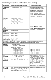
...Motor Fuser Motor Forward Fuser Motor is On/Off Fuser Motor Reverse Fuser Motor is On/Off Fuser Motor Release Fuser Motor is On/Off Motor is On/Off Motor is On/Off Sensor/Switch Tests - Chassis Fan Fan is On/Off Rear Fuser Fan Fan is On/Off Top Fuser Fan Fan ...is H/L, Hop is H/L, Feed H/L Size: SW 1=H/L 2=H/L 3=H/L 4=H/L 5=H/L Note: Media name is Paper/Transparency Actuate and Deactuate the switch. 2-30 Phaser 7300 Color Printer Service Manual Defeat the top cover interlock switch, then resume the test. Tests the functionality of : Letter-SEF, A6-SEF, 11x17-SEF, A3nobi-SEF...
...Motor Fuser Motor Forward Fuser Motor is On/Off Fuser Motor Reverse Fuser Motor is On/Off Fuser Motor Release Fuser Motor is On/Off Motor is On/Off Motor is On/Off Sensor/Switch Tests - Chassis Fan Fan is On/Off Rear Fuser Fan Fan is On/Off Top Fuser Fan Fan ...is H/L, Hop is H/L, Feed H/L Size: SW 1=H/L 2=H/L 3=H/L 4=H/L 5=H/L Note: Media name is Paper/Transparency Actuate and Deactuate the switch. 2-30 Phaser 7300 Color Printer Service Manual Defeat the top cover interlock switch, then resume the test. Tests the functionality of : Letter-SEF, A6-SEF, 11x17-SEF, A3nobi-SEF...

Service Manual
Page 76
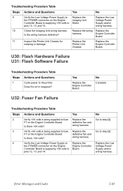
... the Low Voltage Power Supply to Replace the the POWER connector on the Engine Controller Board. Replace the Is the connector damaged or defective? Fuser Fan. pins 12, 13, and 14. Go to Board. Duplex Unit. 3 Inspect the wiring harness from the Replace Engine Duplex Unit to...Controller Board is being supplied to test the Rear Board. Do the fans operate correctly. 2 Verify +34 volts is supplying +34 volts to step [3]. No Go to step [2]. Engine Controller Does the error still appear? Replace wiring harness or connector. 2-60 Phaser 7300 Color Printer Service Manual
... the Low Voltage Power Supply to Replace the the POWER connector on the Engine Controller Board. Replace the Is the connector damaged or defective? Fuser Fan. pins 12, 13, and 14. Go to Board. Duplex Unit. 3 Inspect the wiring harness from the Replace Engine Duplex Unit to...Controller Board is being supplied to test the Rear Board. Do the fans operate correctly. 2 Verify +34 volts is supplying +34 volts to step [3]. No Go to step [2]. Engine Controller Does the error still appear? Replace wiring harness or connector. 2-60 Phaser 7300 Color Printer Service Manual
Service Manual
Page 79
...or damage. Does the error reappear? No Go to the printer. wiring harness. 10 Check the Imaging Unit wiring harness. Replace the Printer Unit Chassis. defective fan and Is there +34 volts? Go to step [3]. harness. U32: Fuser Fan Failure Yes Replace the Engine Controller Board. Replace the Low...being supplied to fuse Replace the F7 on the Engine Controller Board. Replace the wiring Replace the Is the wiring harness defective? defective fan and Is there +34 volts? wiring harness. 4 Verify the Low Voltage Power Supply to Replace the the POWER connector on the...
...or damage. Does the error reappear? No Go to the printer. wiring harness. 10 Check the Imaging Unit wiring harness. Replace the Printer Unit Chassis. defective fan and Is there +34 volts? Go to step [3]. harness. U32: Fuser Fan Failure Yes Replace the Engine Controller Board. Replace the Low...being supplied to fuse Replace the F7 on the Engine Controller Board. Replace the wiring Replace the Is the wiring harness defective? defective fan and Is there +34 volts? wiring harness. 4 Verify the Low Voltage Power Supply to Replace the the POWER connector on the...

Service Manual
Page 88
DC Output: With the DMM set to measure AC voltages, measure for power being supplied to the printer. Verifying Power Supply Operation Verifying the power supply involves four steps: ■ Measuring the input and output voltages. ■ Checking the safety interlocks. &#... 23 11 COM (0V) 24 12 +34 V 25 13 +34 V 26 1 S7300-014 Voltage/Signal Level +34 V +12 V Upper Thermistor Side Thermistor Lower Thermistor Fuser Fuse Duplex Gate Solenoid Front Fan Signal Face Up Solenoid Power Signal Power Signal Power Signal Power Signal 3-72 Phaser 7300 Color Printer Service Manual
DC Output: With the DMM set to measure AC voltages, measure for power being supplied to the printer. Verifying Power Supply Operation Verifying the power supply involves four steps: ■ Measuring the input and output voltages. ■ Checking the safety interlocks. &#... 23 11 COM (0V) 24 12 +34 V 25 13 +34 V 26 1 S7300-014 Voltage/Signal Level +34 V +12 V Upper Thermistor Side Thermistor Lower Thermistor Fuser Fuse Duplex Gate Solenoid Front Fan Signal Face Up Solenoid Power Signal Power Signal Power Signal Power Signal 3-72 Phaser 7300 Color Printer Service Manual

Service Manual
Page 173
... harness under the EMI shield instead of the Printer Unit Chassis. 15. Remove the Side Output Tray Sensor Harness and pull it through the chassis. 16. Disconnect the wiring harness from the fan duct retainer: ■ Toner Sensor Board connector ■ Top Fuser Fan connector ■ Rear Fuser Fan connector 14. Disconnect the serial port wiring...
... harness under the EMI shield instead of the Printer Unit Chassis. 15. Remove the Side Output Tray Sensor Harness and pull it through the chassis. 16. Disconnect the wiring harness from the fan duct retainer: ■ Toner Sensor Board connector ■ Top Fuser Fan connector ■ Rear Fuser Fan connector 14. Disconnect the serial port wiring...

Service Manual
Page 175
... The Face-Up Solenoid connector. 19. Disconnect the following connectors from the front of the printer: ■ The Front Chassis Fan ■ The Front Power Supply Fan ■ The Rear Power Supply Fan ■ The Duplex Solenoid connectors from the Engine Controller Board: ■ The REG, ...FSENS, RSNS and JODEN connectors. ■ The Fuser Exit Sensor connector (Red-Black-Blue wire) located ...
... The Face-Up Solenoid connector. 19. Disconnect the following connectors from the front of the printer: ■ The Front Chassis Fan ■ The Front Power Supply Fan ■ The Rear Power Supply Fan ■ The Duplex Solenoid connectors from the Engine Controller Board: ■ The REG, ...FSENS, RSNS and JODEN connectors. ■ The Fuser Exit Sensor connector (Red-Black-Blue wire) located ...

Service Manual
Page 198
..., and remove the shaft. 1 2 3 G B S7300-167 6-182 Phaser 7300 Color Printer Service Manual Slide the Fuser Exit Roller to the rear of the printer until the front end of the Fuser Exit Roller (item #2), remove 1 G screw securing the ground contact (item #3). 8. Fuser Exit Roller (PL 5.1.1) 1. Remove the Rear Power Supply Fan and Duct (see pg. 6-155). 5. Remove the...
..., and remove the shaft. 1 2 3 G B S7300-167 6-182 Phaser 7300 Color Printer Service Manual Slide the Fuser Exit Roller to the rear of the printer until the front end of the Fuser Exit Roller (item #2), remove 1 G screw securing the ground contact (item #3). 8. Fuser Exit Roller (PL 5.1.1) 1. Remove the Rear Power Supply Fan and Duct (see pg. 6-155). 5. Remove the...

Service Manual
Page 211
Rear Top Cover Damper - Rear Rear Cover MPT Pick Assembly (PL 2.0) Front PS Fan Duplex Transport Assembly Universal Paper Tray 1 (PL 6.0) Top Fuser Fan Duct Foot Right Side Cover (Door A) Top Fuser Cooling Fan MPT Top Cover Temperature/Humidity Sensor Board Pickup Plate Assembly Pickup Cover Assembly Field Replaceable Units (FRU) Parts List 7-195 Part Number...
Rear Top Cover Damper - Rear Rear Cover MPT Pick Assembly (PL 2.0) Front PS Fan Duplex Transport Assembly Universal Paper Tray 1 (PL 6.0) Top Fuser Fan Duct Foot Right Side Cover (Door A) Top Fuser Cooling Fan MPT Top Cover Temperature/Humidity Sensor Board Pickup Plate Assembly Pickup Cover Assembly Field Replaceable Units (FRU) Parts List 7-195 Part Number...

Service Manual
Page 217
... Holder 1 LED Assembly Spring 1 Black LED Wiring Harness 1 Yellow LED Wiring Harness 1 Magenta LED Wiring Harness 1 Cyan LED Wiring Harness 1 Top Cover Inner Frame 1 Rear Fuser Cooling Fan 1 Toner Cartridge Sensor Actuator 1 Toner Sensor Board Field Replaceable Units (FRU) Parts List 7-201 FRU Part List 4.0 -
... Holder 1 LED Assembly Spring 1 Black LED Wiring Harness 1 Yellow LED Wiring Harness 1 Magenta LED Wiring Harness 1 Cyan LED Wiring Harness 1 Top Cover Inner Frame 1 Rear Fuser Cooling Fan 1 Toner Cartridge Sensor Actuator 1 Toner Sensor Board Field Replaceable Units (FRU) Parts List 7-201 FRU Part List 4.0 -
Service Manual
Page 219
... Guide Assembly 1 Fuser Exit Sensor Assembly 1 Fuser Latching Handle (Front) 1 Fuser Latch Handle Spring 1 Top/Side Output Solenoid 1 Fuser Exit Roller Bushing (Front) 1 Duplex Gate Solenoid Assembly 1 Front Power Supply Fan 1 Color Registration Sensor Assembly (includes ADC Sensor) 1 Color Registration Plate Shutter (includes Color Chip for ADC and Tag number) 1 Registration Shutter Spring 1 Color Registration Shutter Solenoid 1 Printer Unit Chassis...
... Guide Assembly 1 Fuser Exit Sensor Assembly 1 Fuser Latching Handle (Front) 1 Fuser Latch Handle Spring 1 Top/Side Output Solenoid 1 Fuser Exit Roller Bushing (Front) 1 Duplex Gate Solenoid Assembly 1 Front Power Supply Fan 1 Color Registration Sensor Assembly (includes ADC Sensor) 1 Color Registration Plate Shutter (includes Color Chip for ADC and Tag number) 1 Registration Shutter Spring 1 Color Registration Shutter Solenoid 1 Printer Unit Chassis...

Service Manual
Page 221
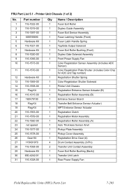
Printer Unit Chassis (2 of 2) and Power Supplies No. 1 2 3 4 5 6 7 8 9 10 11 12 13 Part number 003E55700 116-1556-00 116-1029-00 116-1215-00 116-1034-... 116-1568-00 Harness Kit 116-1554-00 116-1536-00 116-1537-00 116-1064-00 Qty Description 1 Fuser Latching Handle (Rear) 1 Transfer Unit Motor Assembly 1 Front Plate Assembly 1 Front Chassis Fan 1 LVPS Insulator 1 Duplex Exit Paper Guide 1 HVPS Insulator Imaging Unit Contact Assembly (HV) 1 High Voltage Power Supply 1 High Voltage...
Printer Unit Chassis (2 of 2) and Power Supplies No. 1 2 3 4 5 6 7 8 9 10 11 12 13 Part number 003E55700 116-1556-00 116-1029-00 116-1215-00 116-1034-... 116-1568-00 Harness Kit 116-1554-00 116-1536-00 116-1537-00 116-1064-00 Qty Description 1 Fuser Latching Handle (Rear) 1 Transfer Unit Motor Assembly 1 Front Plate Assembly 1 Front Chassis Fan 1 LVPS Insulator 1 Duplex Exit Paper Guide 1 HVPS Insulator Imaging Unit Contact Assembly (HV) 1 High Voltage Power Supply 1 High Voltage...

Service Manual
Page 227
... Kit Front Panel Harness High Voltage Harness Fuser Motor, Transfer Unit Motor MPT Entrance Sensor, Entrance Sensor Board, OHP Sensor Tray 1 Paper Empty Sensor, Paper Low Sensor Tray Lift Motor Tray 1 Paper Feed Sensor Color Registration Sensor and ADC Sensor Imaging Unit ...Sensor Board Entrance Sensor Board Tray Sensors Duplex Unit Engine Controller Board, LVPS Right Door A / Face Up Tray Inline Connector Job Offset, Fuser Fan Imaging Unit Motor Tray 1 Feed Motor, Registration...
... Kit Front Panel Harness High Voltage Harness Fuser Motor, Transfer Unit Motor MPT Entrance Sensor, Entrance Sensor Board, OHP Sensor Tray 1 Paper Empty Sensor, Paper Low Sensor Tray Lift Motor Tray 1 Paper Feed Sensor Color Registration Sensor and ADC Sensor Imaging Unit ...Sensor Board Entrance Sensor Board Tray Sensors Duplex Unit Engine Controller Board, LVPS Right Door A / Face Up Tray Inline Connector Job Offset, Fuser Fan Imaging Unit Motor Tray 1 Feed Motor, Registration...

Service Manual
Page 261
...: ■ Transfer belt entrance sensor ■ Registration entrance sensor ■ MPT entrance sensor ■ Waste toner full sensor 8. Upon insertion of the paper in the printer, the plate's four rows activate four switches on page 8-246 4. See "Engine Controller Board Connectors" on page 8-246 ■ Connectors - 3. The engine controller board synchronizes...
...: ■ Transfer belt entrance sensor ■ Registration entrance sensor ■ MPT entrance sensor ■ Waste toner full sensor 8. Upon insertion of the paper in the printer, the plate's four rows activate four switches on page 8-246 4. See "Engine Controller Board Connectors" on page 8-246 ■ Connectors - 3. The engine controller board synchronizes...

Service Manual
Page 262
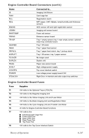
... solenoid Registration and tray 1 motor Toner sensor board Fuser and Transfer Motors Top and rear fuser fans, right and left offset solenoids 8-246 Phaser 7300 Color Printer Service Manual 2 1 OPTN 19 Engine Controller Board Connectors SHUTTER 8 1 HOPFF F7 1 BELTHET F5 F2 F3 F4 81 JOBOFF I D 16 1 20 10 1 FAN 12 RCL 3 1 RSNS PARTTEMP 2 1 REG 15 1 2 16 1 10...
... solenoid Registration and tray 1 motor Toner sensor board Fuser and Transfer Motors Top and rear fuser fans, right and left offset solenoids 8-246 Phaser 7300 Color Printer Service Manual 2 1 OPTN 19 Engine Controller Board Connectors SHUTTER 8 1 HOPFF F7 1 BELTHET F5 F2 F3 F4 81 JOBOFF I D 16 1 20 10 1 FAN 12 RCL 3 1 RSNS PARTTEMP 2 1 REG 15 1 2 16 1 10...
Service Manual
Page 263
... clutch MPT paper, OHP, liftplate, temp/humidity and thickness sensors ADC sensor, left and right registration sensor Imaging unit sensor board Fuser exit sensor Entrance sensor board Tray 1 empty sensor, tray 1 near empty sensor, optional lower tray controller board. Tray 1 lift motor Tray 1 paper feed sensor Tray 1 ... to the Cyan Imaging Unit and Transfer Unit Motor F6 +5 Volts for Engine Controller Board functions F7 +34 volts to the: ■ Electrical Card Cage Fan ■ Front LVPS Fan ■ Rear LVPS Fan ■ Rear Fuser Fan ■ Top Fuser Fan F8 +34 volts to ...
... clutch MPT paper, OHP, liftplate, temp/humidity and thickness sensors ADC sensor, left and right registration sensor Imaging unit sensor board Fuser exit sensor Entrance sensor board Tray 1 empty sensor, tray 1 near empty sensor, optional lower tray controller board. Tray 1 lift motor Tray 1 paper feed sensor Tray 1 ... to the Cyan Imaging Unit and Transfer Unit Motor F6 +5 Volts for Engine Controller Board functions F7 +34 volts to the: ■ Electrical Card Cage Fan ■ Front LVPS Fan ■ Rear LVPS Fan ■ Rear Fuser Fan ■ Top Fuser Fan F8 +34 volts to ...

Service Manual
Page 269
...9. COM(0V) 14. 5VLOOP 1. 10 1 FAN1 13 JOBOFF 3. CCAGEFANON(34V) White Black Red Card Cage Fan Engine Controller Board 10. COM(3.8V) Red Rear Fuser Fan Top Fuser Fan Right Offset Solenoid Left Offset Solenoid KPOW2 13 1. FUGATESOL(32V) Red 2. COM(0V) 11. PWRSIG Black Low... 2. COM(0V) 10. FRONTFANSIG 22. COM(0V) 12. GND 3. GND 1. GND 5. OFFSETSOLL 1. FFUSERFAN0N(34V) Black Red Front Fuser Fan 3. CCAGEFANERROR 2. GND CPOW2 13 Green Black 3 1 CN5 2121 31 CN9 CN10 CN8 2. FPSFANON(34V) White Black Red Front Power Supply...
...9. COM(0V) 14. 5VLOOP 1. 10 1 FAN1 13 JOBOFF 3. CCAGEFANON(34V) White Black Red Card Cage Fan Engine Controller Board 10. COM(3.8V) Red Rear Fuser Fan Top Fuser Fan Right Offset Solenoid Left Offset Solenoid KPOW2 13 1. FUGATESOL(32V) Red 2. COM(0V) 11. PWRSIG Black Low... 2. COM(0V) 10. FRONTFANSIG 22. COM(0V) 12. GND 3. GND 1. GND 5. OFFSETSOLL 1. FFUSERFAN0N(34V) Black Red Front Fuser Fan 3. CCAGEFANERROR 2. GND CPOW2 13 Green Black 3 1 CN5 2121 31 CN9 CN10 CN8 2. FPSFANON(34V) White Black Red Front Power Supply...


