
Service Manual
Page 38
... Replace Magenta Toner Cartridge 66 Replace Yellow Toner Cartridge 67 Replace Black Toner Cartridge 68 Replace Cyan Imaging Unit 69 Replace Magenta Imaging Unit 70 Replace Yellow Imaging Unit 71 Replace Black Imaging Unit 72 Replace Transfer Unit 73 Close Right Door A 74 Close Right Door B 75 Close Right Door C 76 Close Right Door D 77 Close... 2 - 47 2 - 47 2 - 53 2 - 53 2 - 53 2 - 53 2 - 52 2 - 52 2 - 52 2 - 52 2 - 55 2 - 49 2 - 49 2 - 49 2 - 49 2 - 49 2 - 49 2 - 48 2 - 50 2 - 44 2 - 44 2 - 44 2 - 44 2 - 44 2-22 Phaser 7300 Color Printer Service Manual
... Replace Magenta Toner Cartridge 66 Replace Yellow Toner Cartridge 67 Replace Black Toner Cartridge 68 Replace Cyan Imaging Unit 69 Replace Magenta Imaging Unit 70 Replace Yellow Imaging Unit 71 Replace Black Imaging Unit 72 Replace Transfer Unit 73 Close Right Door A 74 Close Right Door B 75 Close Right Door C 76 Close Right Door D 77 Close... 2 - 47 2 - 47 2 - 53 2 - 53 2 - 53 2 - 53 2 - 52 2 - 52 2 - 52 2 - 52 2 - 55 2 - 49 2 - 49 2 - 49 2 - 49 2 - 49 2 - 49 2 - 48 2 - 50 2 - 44 2 - 44 2 - 44 2 - 44 2 - 44 2-22 Phaser 7300 Color Printer Service Manual
Service Manual
Page 46
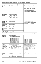
... Diagnostics Tests and Functions Table (cont'd.) Menu Item Front Panel Display Results Functional Definition transfer unit Transfer Motor is On/Off Motor Fuser Unit Motor Duplex Unit Motor Job Offset Motor Fuser Motor Forward Fuser Motor is On/Off Fuser Motor Reverse ...Lift is H/L, Hop is H/L, Feed H/L Size: SW 1=H/L 2=H/L 3=H/L 4=H/L 5=H/L Note: Media name is Paper/Transparency Actuate and Deactuate the switch. 2-30 Phaser 7300 Color Printer Service Manual Tests the functionality of : Letter-SEF, A6-SEF, 11x17-SEF, A3nobi-SEF, Executive-SEF, Legal14-SEF, A3-SEF, B4-SEF, A4-...
... Diagnostics Tests and Functions Table (cont'd.) Menu Item Front Panel Display Results Functional Definition transfer unit Transfer Motor is On/Off Motor Fuser Unit Motor Duplex Unit Motor Job Offset Motor Fuser Motor Forward Fuser Motor is On/Off Fuser Motor Reverse ...Lift is H/L, Hop is H/L, Feed H/L Size: SW 1=H/L 2=H/L 3=H/L 4=H/L 5=H/L Note: Media name is Paper/Transparency Actuate and Deactuate the switch. 2-30 Phaser 7300 Color Printer Service Manual Tests the functionality of : Letter-SEF, A6-SEF, 11x17-SEF, A3nobi-SEF, Executive-SEF, Legal14-SEF, A3-SEF, B4-SEF, A4-...

Service Manual
Page 52
...Test Executing..... Passed / Failed Performs an extended memory test on self test. 2-36 Phaser 7300 Color Printer Service Manual Exit - Exits service diagnostics to the printer after executing this test. Service Diagnostics Tests and Functions Table (cont'd.) Menu Item Front...nnn % used CRU Counter Resets: Resets the selected Customer Replaceable Consumable count on the engine. Y / N Resetting Fuser Count Reset transfer Reset transfer unit Count? This resets the image count only, not the pixel count. Tests the basic functionality of the Image Processor Board.
...Test Executing..... Passed / Failed Performs an extended memory test on self test. 2-36 Phaser 7300 Color Printer Service Manual Exit - Exits service diagnostics to the printer after executing this test. Service Diagnostics Tests and Functions Table (cont'd.) Menu Item Front...nnn % used CRU Counter Resets: Resets the selected Customer Replaceable Consumable count on the engine. Y / N Resetting Fuser Count Reset transfer Reset transfer unit Count? This resets the image count only, not the pixel count. Tests the basic functionality of the Image Processor Board.

Service Manual
Page 54
... properly. or remove debris. Main Feed Motor Transfer Unit Motor Registration Motor Registration Clutch Fuser Motor Replace the Engine Controller Board. Engine Controller wiring harness Are the wiring harnesses properly connected and free from damage or defects. and/or the problem motor/clutch. 2-38 Phaser 7300 Color Printer Service Manual Replace the following motors/clutches...
... properly. or remove debris. Main Feed Motor Transfer Unit Motor Registration Motor Registration Clutch Fuser Motor Replace the Engine Controller Board. Engine Controller wiring harness Are the wiring harnesses properly connected and free from damage or defects. and/or the problem motor/clutch. 2-38 Phaser 7300 Color Printer Service Manual Replace the following motors/clutches...

Service Manual
Page 74
... Controller Controller Board is being supplied to step [3]. following order: Does the error still appear? No Go to the printer. Replace the Low Voltage Power Supply and/or wiring harness. Replace the Engine Controller Board. U0: Engine ROM Failure ...Unit. 2-58 Phaser 7300 Color Printer Service Manual Go to fuse Replace the fan. pins 12, 13, and 14. 4 Turn the printer off, remove the Duplex Replace in the Unit, then turn the printer back on the Engine Controller Board. No Complete Replace the EEPROM for proper Go to step [2]. Transfer Unit...
... Controller Controller Board is being supplied to step [3]. following order: Does the error still appear? No Go to the printer. Replace the Low Voltage Power Supply and/or wiring harness. Replace the Engine Controller Board. U0: Engine ROM Failure ...Unit. 2-58 Phaser 7300 Color Printer Service Manual Go to fuse Replace the fan. pins 12, 13, and 14. 4 Turn the printer off, remove the Duplex Replace in the Unit, then turn the printer back on the Engine Controller Board. No Complete Replace the EEPROM for proper Go to step [2]. Transfer Unit...

Service Manual
Page 78
...Board to step [9]. IU Sensor. Board and the Engine Controller Board at Engine Controller the JODEN connector. See "Transfer Unit Arm and Gear Up/Down Movement of the Imaging Units" on the Engine Go to step [10]. Does the gear stop rotating. Go to see if it is...wiring harness. Y pin 9 to pin 12 M pin 1 to pin 3 C pin 5 to pin 6 K pin 10 to step [3]. Transfer Unit. Cyan = F5 Magenta = F2 Yellow = F3 Black = F4 2-62 Phaser 7300 Color Printer Service Manual Drum Contact Are the contacts damaged or dirty? Assembly. 3 Use service diagnostics to test the CMYK Go to...
...Board to step [9]. IU Sensor. Board and the Engine Controller Board at Engine Controller the JODEN connector. See "Transfer Unit Arm and Gear Up/Down Movement of the Imaging Units" on the Engine Go to step [10]. Does the gear stop rotating. Go to see if it is...wiring harness. Y pin 9 to pin 12 M pin 1 to pin 3 C pin 5 to pin 6 K pin 10 to step [3]. Transfer Unit. Cyan = F5 Magenta = F2 Yellow = F3 Black = F4 2-62 Phaser 7300 Color Printer Service Manual Drum Contact Are the contacts damaged or dirty? Assembly. 3 Use service diagnostics to test the CMYK Go to...
Service Manual
Page 96
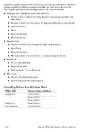
... in the Scan Direction Repeating Defects Identification Chart FRU or CRC Imaging Unit Transfer Unit Fuser Assembly Distance between Defects 94 mm (3.70 in.) 50 mm (1.97 in.) 44 mm (1.73 in.) 58 mm (2.29 in.) 143 mm (5.62 in.) 3-80 Phaser 7300 Color Printer Service Manual Some print-quality problems can be associated with paper...
... in the Scan Direction Repeating Defects Identification Chart FRU or CRC Imaging Unit Transfer Unit Fuser Assembly Distance between Defects 94 mm (3.70 in.) 50 mm (1.97 in.) 44 mm (1.73 in.) 58 mm (2.29 in.) 143 mm (5.62 in.) 3-80 Phaser 7300 Color Printer Service Manual Some print-quality problems can be associated with paper...

Service Manual
Page 98
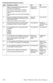
... POWER connector pins 1, 2, 3, 4, 5, 6, 7 and 8 on the Toner Sensor Board? Replace defective wiring harness. Replace the Transfer Unit. Replace the LVPS or wiring harness. No Replace the LVPS. Replace the Engine Control Board. Replace the HVPS. 3-82 Phaser 7300 Color Printer Service Manual Yes Replace the Toner Sensor Board. Troubleshooting Procedure (cont'd.) Step 8 9 Question or Action...
... POWER connector pins 1, 2, 3, 4, 5, 6, 7 and 8 on the Toner Sensor Board? Replace defective wiring harness. Replace the Transfer Unit. Replace the LVPS or wiring harness. No Replace the LVPS. Replace the Engine Control Board. Replace the HVPS. 3-82 Phaser 7300 Color Printer Service Manual Yes Replace the Toner Sensor Board. Troubleshooting Procedure (cont'd.) Step 8 9 Question or Action...

Service Manual
Page 100
KPOW2 YPOW2 MPOW2 CPOW2 10 Is +5V supplied to the POWER connector pins Replace the 1, 2, 3, 4, 5, 6, 7 and 8 on the LED heads undamaged, properly routed and seated? Go to Pin 1 of the problem LED Replace the Head assembly? Yes Go to step [9]. 9 Is +5V supplied to step [10]. No Replace or reseat the wiring harness. Imaging Unit. Board. Replace in the following order: Transfer Unit LVPS 3-84 Phaser 7300 Color Printer Service Manual Troubleshooting Procedure (cont'd.) Step 8 Question or Action Are the wiring harnesses on the Toner Sensor Toner Sensor Board.
KPOW2 YPOW2 MPOW2 CPOW2 10 Is +5V supplied to the POWER connector pins Replace the 1, 2, 3, 4, 5, 6, 7 and 8 on the LED heads undamaged, properly routed and seated? Go to Pin 1 of the problem LED Replace the Head assembly? Yes Go to step [9]. 9 Is +5V supplied to step [10]. No Replace or reseat the wiring harness. Imaging Unit. Board. Replace in the following order: Transfer Unit LVPS 3-84 Phaser 7300 Color Printer Service Manual Troubleshooting Procedure (cont'd.) Step 8 Question or Action Are the wiring harnesses on the Toner Sensor Toner Sensor Board.

Service Manual
Page 102
Yes Go to step [8]. 8 Is +34V supplied to the HVOLT connector Pin 2 Go to the POWER connector pins 12, 13, and 14 on the Engine Controller Board? 9 Inspect the high-voltage wiring harnesses. Replace the Engine Control Board. on the Engine Controller Board? Replace any defective wiring harnesses. Replace the Transfer Unit. No Replace the LVPS or wiring harness. Replace the HVPS. 3-86 Phaser 7300 Color Printer Service Manual Troubleshooting Procedure (cont'd.) Step 7 Question or Action Is +34V supplied to step [9].
Yes Go to step [8]. 8 Is +34V supplied to the HVOLT connector Pin 2 Go to the POWER connector pins 12, 13, and 14 on the Engine Controller Board? 9 Inspect the high-voltage wiring harnesses. Replace the Engine Control Board. on the Engine Controller Board? Replace any defective wiring harnesses. Replace the Transfer Unit. No Replace the LVPS or wiring harness. Replace the HVPS. 3-86 Phaser 7300 Color Printer Service Manual Troubleshooting Procedure (cont'd.) Step 7 Question or Action Is +34V supplied to step [9].

Service Manual
Page 104
No Replace the Engine Control Board. Troubleshooting Procedure (cont'd.) Step 6 Question or Action Is +34V supplied to step [7]. 7 Inspect the high-voltage wiring harnesses. Yes Go to the HVOLT connector Pin 2 on the Engine Controller Board.? defective wiring harnesses. Replace any Are the wiring harnesses defective? HVPS. 3-88 Phaser 7300 Color Printer Service Manual Replace in the following order: Transfer Unit.
No Replace the Engine Control Board. Troubleshooting Procedure (cont'd.) Step 6 Question or Action Is +34V supplied to step [7]. 7 Inspect the high-voltage wiring harnesses. Yes Go to the HVOLT connector Pin 2 on the Engine Controller Board.? defective wiring harnesses. Replace any Are the wiring harnesses defective? HVPS. 3-88 Phaser 7300 Color Printer Service Manual Replace in the following order: Transfer Unit.
Service Manual
Page 106
...to step [8]. on the LED heads undamaged, properly routed and seated? No Go to Pin 1 of the problem color with the Imaging Unit? Replace or reseat the wiring harness. Replace the LVPS or wiring harness. Are the wiring harnesses on the Engine Controller...on the contacts? Remove the Imaging Units and the Transfer Unit and check for defects. Yes Replace the Imaging Unit. Has the problem color moved with any defective wiring harnesses. Replace the HVPS. 3-90 Phaser 7300 Color Printer Service Manual Replace the Transfer Unit. Note: Remove the keys before ...
...to step [8]. on the LED heads undamaged, properly routed and seated? No Go to Pin 1 of the problem color with the Imaging Unit? Replace or reseat the wiring harness. Replace the LVPS or wiring harness. Are the wiring harnesses on the Engine Controller...on the contacts? Remove the Imaging Units and the Transfer Unit and check for defects. Yes Replace the Imaging Unit. Has the problem color moved with any defective wiring harnesses. Replace the HVPS. 3-90 Phaser 7300 Color Printer Service Manual Replace the Transfer Unit. Note: Remove the keys before ...

Service Manual
Page 108
No Go to step [9]. Troubleshooting Procedure (cont'd.) Step 8 9 Question or Action Check the Imaging Unit contacts (3-pin contacts) and make sure they are in the following order: Transfer Unit HVPS 3-92 Phaser 7300 Color Printer Service Manual Clean the contacts. Yes Clean the or replace the Drum Contacts. Remove the Imaging Units and the Transfer Unit and check for toner contamination on the high voltage contacts. Replace in good working condition and not contaminated.
No Go to step [9]. Troubleshooting Procedure (cont'd.) Step 8 9 Question or Action Check the Imaging Unit contacts (3-pin contacts) and make sure they are in the following order: Transfer Unit HVPS 3-92 Phaser 7300 Color Printer Service Manual Clean the contacts. Yes Clean the or replace the Drum Contacts. Remove the Imaging Units and the Transfer Unit and check for toner contamination on the high voltage contacts. Replace in good working condition and not contaminated.

Service Manual
Page 134
...Assemblies. The anvil should be completed through the MPT up or down as required, until the anvil just touches the transparency. The Phaser 7300 printer has the ability to about 12 mm (.5 in.) past the Registration Rollers A, see diagram below. ATS Anvil Adjustment a. To... damage to properly calibrate the ATS Sensor, you MUST use Phaser 35-Series Premium Transparencies. Door A and manually feed a sheet of proper adjustment. 4-118 Phaser 7300 Color Printer Service Manual S7300-115 b. Note: Ensure the Transfer Unit Belt Entrance Sensor does not interfere with the transparency sheet,...
...Assemblies. The anvil should be completed through the MPT up or down as required, until the anvil just touches the transparency. The Phaser 7300 printer has the ability to about 12 mm (.5 in.) past the Registration Rollers A, see diagram below. ATS Anvil Adjustment a. To... damage to properly calibrate the ATS Sensor, you MUST use Phaser 35-Series Premium Transparencies. Door A and manually feed a sheet of proper adjustment. 4-118 Phaser 7300 Color Printer Service Manual S7300-115 b. Note: Ensure the Transfer Unit Belt Entrance Sensor does not interfere with the transparency sheet,...

Service Manual
Page 146
... Unit Motors (PL 5.2.13 6 - 186 Transfer Unit and Fuser Motor Assembly (PL 5.2.2 6 - 187 Color Registration Plate Shutter (PL 5.1.11 6 - 188 Color Registration Sensor Assembly (PL 5.1.10 6 - 189 Color Registration Shutter Solenoid (PL 5.1.13 6 - 190 LED Head 600 dpi (PL 4.9a) and LED Head Holder (PL 4.9b 6 - 191 (Imaging Unit) Drum Contact Assembly (PL 5.1.27 6 - 192 6-130 Phaser 7300 Color Printer...
... Unit Motors (PL 5.2.13 6 - 186 Transfer Unit and Fuser Motor Assembly (PL 5.2.2 6 - 187 Color Registration Plate Shutter (PL 5.1.11 6 - 188 Color Registration Sensor Assembly (PL 5.1.10 6 - 189 Color Registration Shutter Solenoid (PL 5.1.13 6 - 190 LED Head 600 dpi (PL 4.9a) and LED Head Holder (PL 4.9b 6 - 191 (Imaging Unit) Drum Contact Assembly (PL 5.1.27 6 - 192 6-130 Phaser 7300 Color Printer...

Service Manual
Page 172
... 6. Remove the Left Side Cover (see pg. 6-135). 4. Remove the Multi-Purpose Tray (see pg. 6-142). 3. Remove the Fuser and the Transfer Unit. 2. Remove the Image Processor Board (see pg. 6-140). 9. Remove the 5 G screws and the 3 B screw securing the Front Shield Plate and... corner of the Electrical Card Cage. 12. B B G G G B G G S7300-113 8. Printer Unit Chassis (PL 5.1.14) 1. Note: Label harnesses and ribbon cables to aid in place. 6-156 Phaser 7300 Color Printer Service Manual Remove the 5 G and 2 B screws securing the Left Side Shield Plate and remove the plate...
... 6. Remove the Left Side Cover (see pg. 6-135). 4. Remove the Multi-Purpose Tray (see pg. 6-142). 3. Remove the Fuser and the Transfer Unit. 2. Remove the Image Processor Board (see pg. 6-140). 9. Remove the 5 G screws and the 3 B screw securing the Front Shield Plate and... corner of the Electrical Card Cage. 12. B B G G G B G G S7300-113 8. Printer Unit Chassis (PL 5.1.14) 1. Note: Label harnesses and ribbon cables to aid in place. 6-156 Phaser 7300 Color Printer Service Manual Remove the 5 G and 2 B screws securing the Left Side Shield Plate and remove the plate...

Service Manual
Page 228
Flag Kit Part number 116-1036-01 Name / Parts Included Flag Kit Stack Full Sensor Actuator Toner Sensor Actuator (qty of 4) Exit Sensor Actuator Registration Entrance Sensor A Actuator Registration Entrance Sensor B Actuator Registration A Exit Sensor Actuator Tray 1 Paper Low Actuator Tray 1 No Paper Sensor Actuator Transfer Unit Waste Full Sensor Actuator 7-212 Phaser 7300 Color Printer Service Manual
Flag Kit Part number 116-1036-01 Name / Parts Included Flag Kit Stack Full Sensor Actuator Toner Sensor Actuator (qty of 4) Exit Sensor Actuator Registration Entrance Sensor A Actuator Registration Entrance Sensor B Actuator Registration A Exit Sensor Actuator Tray 1 Paper Low Actuator Tray 1 No Paper Sensor Actuator Transfer Unit Waste Full Sensor Actuator 7-212 Phaser 7300 Color Printer Service Manual

Service Manual
Page 230
Customer Replaceable Consumables 3 4 1 3 2 4 7300-30 No. Consumable 1 Fuser 110 Volt 220 Volt 2 Transfer Unit 3 Toner Cartridges: Standard Capacity Yellow Standard Capacity Magenta ' Standard Capacity Cyan Standard Capacity Black High Capacity Yellow High Capacity Magenta High Capacity Cyan High Capacity Black 4 Imaging Units Cyan Magenta Yellow Black Part Number 016-1998-00 016-1999-00... 016-1979-00 016-1978-00 016-1977-00 016-1980-00 016-1993-00 016-1994-00 016-1995-00 016-1996-00 7-214 Phaser 7300 Color Printer Service Manual
Customer Replaceable Consumables 3 4 1 3 2 4 7300-30 No. Consumable 1 Fuser 110 Volt 220 Volt 2 Transfer Unit 3 Toner Cartridges: Standard Capacity Yellow Standard Capacity Magenta ' Standard Capacity Cyan Standard Capacity Black High Capacity Yellow High Capacity Magenta High Capacity Cyan High Capacity Black 4 Imaging Units Cyan Magenta Yellow Black Part Number 016-1998-00 016-1999-00... 016-1979-00 016-1978-00 016-1977-00 016-1980-00 016-1993-00 016-1994-00 016-1995-00 016-1996-00 7-214 Phaser 7300 Color Printer Service Manual

Service Manual
Page 237
... electrostatic image on the imaging unit after transfer. 7. The LED head emits light to the back side of heat and pressure. Developing and recovery of the Printing Process The following steps summarize the xerographic print process for the Phaser 7300 Printer. 1. Summary of excessive toner... - DC voltage applies a negative charge to the paper using a combination of the paper. The toner image on the drum surface. A cleaning blade, located on the transfer unit, scrapes off excess toner left...
... electrostatic image on the imaging unit after transfer. 7. The LED head emits light to the back side of heat and pressure. Developing and recovery of the Printing Process The following steps summarize the xerographic print process for the Phaser 7300 Printer. 1. Summary of excessive toner... - DC voltage applies a negative charge to the paper using a combination of the paper. The toner image on the drum surface. A cleaning blade, located on the transfer unit, scrapes off excess toner left...

Service Manual
Page 246
Drum K Y M C Transfer Unit Transfer roller Transfer belt motor S7300-138 8-230 Phaser 7300 Color Printer Service Manual Transfer Unit The transfer unit motor turns clockwise driving the transfer unit belt. Inside the transfer unit, a transfer roller is located just under the imaging unit for each colors imaging unit drum. When the transfer-belt motor and imaging unit motors are activated, they carry the paper on the transfer belt to each color, with the transfer belt...
Drum K Y M C Transfer Unit Transfer roller Transfer belt motor S7300-138 8-230 Phaser 7300 Color Printer Service Manual Transfer Unit The transfer unit motor turns clockwise driving the transfer unit belt. Inside the transfer unit, a transfer roller is located just under the imaging unit for each colors imaging unit drum. When the transfer-belt motor and imaging unit motors are activated, they carry the paper on the transfer belt to each color, with the transfer belt...

