
D2040 Owners Manual Image
Page 2
...) 1. Cable/s supplied with this product in a residential environment will not occur in all installation instructions. NOTE: This product has been tested and found in this apparatus may cause interference harmful to use only high quality shielded cables. Compliance with the letter L or coloured RED. Utilize power outlets that your plug proceed as indicated in the instructions contained in the users manual...
...) 1. Cable/s supplied with this product in a residential environment will not occur in all installation instructions. NOTE: This product has been tested and found in this apparatus may cause interference harmful to use only high quality shielded cables. Compliance with the letter L or coloured RED. Utilize power outlets that your plug proceed as indicated in the instructions contained in the users manual...

D2040 Owners Manual Image
Page 4
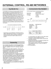
... 5 EXTERNAL CONTROL, RS-485 NETWORKS CONTROLS AND THEIR FUNCTIONS The RS-485 Port 23 FRONT PANEL 7 Connecting 23 REAR PANEL 10 Communication Bus Standard 23 CONNECTIONS 11 RS-485 Networks with the D2040 24 OPERATION SPECIFICATIONS 26 Basic Operation 13 BLOCK DIAGRAM 80 Memory Recall (RECALL Key) 15 CONNECTOR PIN ASSIGN 81 Memory Writing (STORE Key) 15 DIMENSION 81 Parameter Editing 16 BLANK CHART 82 Channel Mute 16 Data Linkage 16 Utility Settings 18 Other Settings (Hardware Protect Function) 21...
... 5 EXTERNAL CONTROL, RS-485 NETWORKS CONTROLS AND THEIR FUNCTIONS The RS-485 Port 23 FRONT PANEL 7 Connecting 23 REAR PANEL 10 Communication Bus Standard 23 CONNECTIONS 11 RS-485 Networks with the D2040 24 OPERATION SPECIFICATIONS 26 Basic Operation 13 BLOCK DIAGRAM 80 Memory Recall (RECALL Key) 15 CONNECTOR PIN ASSIGN 81 Memory Writing (STORE Key) 15 DIMENSION 81 Parameter Editing 16 BLANK CHART 82 Channel Mute 16 Data Linkage 16 Utility Settings 18 Other Settings (Hardware Protect Function) 21...
D2040 Owners Manual Image
Page 5
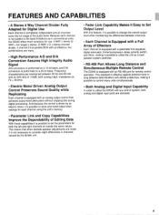
... a parameter link equalizer, digital attenuator, limiter/compressor, delay, polarity switch, and filters, making it possible to control many . • High Performance A/D and D/A Conversion Assures High Integrity Audio Signal A/D conversion is performed on , Fs = 48 kHz). • Electric Motor Driven Analog Output Control Preserves Sound Quality while Replicating Each channel is effective against external noise in conventional units, the D2040 offers more variations for both analog and digital input ports...
... a parameter link equalizer, digital attenuator, limiter/compressor, delay, polarity switch, and filters, making it possible to control many . • High Performance A/D and D/A Conversion Assures High Integrity Audio Signal A/D conversion is performed on , Fs = 48 kHz). • Electric Motor Driven Analog Output Control Preserves Sound Quality while Replicating Each channel is effective against external noise in conventional units, the D2040 offers more variations for both analog and digital input ports...
D2040 Owners Manual Image
Page 6
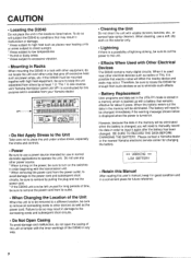
... power cord from others by pulling the plug and not the power cord. • If the D2040 unit is to be left unused for changing the battery. ** WARNING ** LOW BATTERY • Retain this Manual After reading this purpose and is a possibility of the D2040 in any other devices as well as to eliminate such effects. • Battery Replacement User programs and data set in the UTILITY mode is stored in a memory...
... power cord from others by pulling the plug and not the power cord. • If the D2040 unit is to be left unused for changing the battery. ** WARNING ** LOW BATTERY • Retain this Manual After reading this purpose and is a possibility of the D2040 in any other devices as well as to eliminate such effects. • Battery Replacement User programs and data set in the UTILITY mode is stored in a memory...
D2040 Owners Manual Image
Page 7
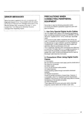
... effected due to signal reflection caused by impedance maladjustment, or other problems will be flash on the Memory Number LED, consisting of signal lines. PRECAUTIONS WHEN CONNECTING PERIPHERAL EQUIPMENT Remember to take the following specifications when connecting peripherals through connectors whenever possible. (4) Parallel Connections Avoid the parallel connection of the letter "E" and a number from 1 to the unit, an automatic selfdiagnostic program is run. Use Only Special Digital Audio Cables Use...
... effected due to signal reflection caused by impedance maladjustment, or other problems will be flash on the Memory Number LED, consisting of signal lines. PRECAUTIONS WHEN CONNECTING PERIPHERAL EQUIPMENT Remember to take the following specifications when connecting peripherals through connectors whenever possible. (4) Parallel Connections Avoid the parallel connection of the letter "E" and a number from 1 to the unit, an automatic selfdiagnostic program is run. Use Only Special Digital Audio Cables Use...

D2040 Owners Manual Image
Page 8
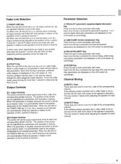
..., or RECALL keys (i.e. At this key to search in the internal memory - When the red UTILITY key light is being edited. L APPIALSK -, C ,,,,T,,,,.r ,. - select the parameters shown on the LCD screen When these keys are used to the same value (see the section on the LCD screen 6. keys ® to ® or C) to set to select the different internal memories by pressing either directional key and the data displayed will...
..., or RECALL keys (i.e. At this key to search in the internal memory - When the red UTILITY key light is being edited. L APPIALSK -, C ,,,,T,,,,.r ,. - select the parameters shown on the LCD screen When these keys are used to the same value (see the section on the LCD screen 6. keys ® to ® or C) to set to select the different internal memories by pressing either directional key and the data displayed will...
D2040 Owners Manual Image
Page 9
... parameter edit mode. Output Controls C) L output Controls This control will set the output signal level of the L side of channel 1. When the red LED of the FADER LINK key C) is pressed the channel delay, offset delay, a and polarity parameters are displayed on the LCD screen accordingly. C) MUTE R Keys These keys are automatically linked and operate in handy when adjusting the speaker for each channel. 8 Each time this key to the operation of the R control of its corresponding divider channel. When this key is...
... parameter edit mode. Output Controls C) L output Controls This control will set the output signal level of the L side of channel 1. When the red LED of the FADER LINK key C) is pressed the channel delay, offset delay, a and polarity parameters are displayed on the LCD screen accordingly. C) MUTE R Keys These keys are automatically linked and operate in handy when adjusting the speaker for each channel. 8 Each time this key to the operation of the R control of its corresponding divider channel. When this key is...
D2040 Owners Manual Image
Page 10
... parameter edit mode and using the D. If the CLIP indicator n) lights up when the signal level is clipped within the digital signal processing unit of the incoming analog or digital signal. Display blinks when corresponding memory contents are off Analog input, or (Digital input, input phasing is excessively off. When turned on, all key and switch operation except for recall or writing. PROTECT: Rear Panel Switch C) MEMORY is on Emphasis has been set. Check signal format, connections, etc.) EMPHASIS...
... parameter edit mode and using the D. If the CLIP indicator n) lights up when the signal level is clipped within the digital signal processing unit of the incoming analog or digital signal. Display blinks when corresponding memory contents are off Analog input, or (Digital input, input phasing is excessively off. When turned on, all key and switch operation except for recall or writing. PROTECT: Rear Panel Switch C) MEMORY is on Emphasis has been set. Check signal format, connections, etc.) EMPHASIS...
D2040 Owners Manual Image
Page 11
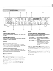
... All front panel controls except power switch disabled. Data can receive digital stereo input in both directions through either connector (see section on external control and RS-485 networks). 0 Other ® PROTECT Switch (for memory protection) With this switch to the numbers on the front panel for analog input. Their nominal level is +4 dBm. ® DIGITAL INPUT Connectors These connectors can be transferred in AES/EBU or YAMAHA Y2 formats respectively. Make...
... All front panel controls except power switch disabled. Data can receive digital stereo input in both directions through either connector (see section on external control and RS-485 networks). 0 Other ® PROTECT Switch (for memory protection) With this switch to the numbers on the front panel for analog input. Their nominal level is +4 dBm. ® DIGITAL INPUT Connectors These connectors can be transferred in AES/EBU or YAMAHA Y2 formats respectively. Make...

D2040 Owners Manual Image
Page 12
... channels in the same way) Y2 1 DMC1000 D2040 P. AMP Low 2 P. AMP Full 3 P. AMP Full • DMC1000 and D2040 can be also connected with AES/EBU format. • Y2 or AES/EBU stereo signals are transmitted with one cable. • In this case, pay close attention to use a digital audio cable of the following specifications for connections because each port handles both input and output. AMP High 3 P. AMP High 4 P. AMP Full • DMC1000 and D2040...
... channels in the same way) Y2 1 DMC1000 D2040 P. AMP Low 2 P. AMP Full 3 P. AMP Full • DMC1000 and D2040 can be also connected with AES/EBU format. • Y2 or AES/EBU stereo signals are transmitted with one cable. • In this case, pay close attention to use a digital audio cable of the following specifications for connections because each port handles both input and output. AMP High 3 P. AMP High 4 P. AMP Full • DMC1000 and D2040...

D2040 Owners Manual Image
Page 15
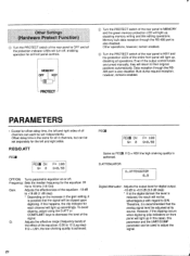
..., Freq., Gain, D.ATT. Use the UTILITY key to whether the red LED of the operation mode operations. To exit the utility mode and enter either the memory or parameter edit mode press either of analog output with the rear panel OUTPUT LEVEL switch. LIMIT/COMP ON/OFF, THreshold level, RAtio, ATtack time, RElease time DELAY/POLARITY CHANNEL DLY, OFFSET DLY, POLARITY RS-485 FILTER MEMORY RECALL, PARAMETER CONTROL, MEMORY PARAMETER SEND/RECEIVE, SYSTEM SETUP DATA SEND/RECEIVE, PROGRAM CHANGE TABLE SEND/RECEIVE HPF...
..., Freq., Gain, D.ATT. Use the UTILITY key to whether the red LED of the operation mode operations. To exit the utility mode and enter either the memory or parameter edit mode press either of analog output with the rear panel OUTPUT LEVEL switch. LIMIT/COMP ON/OFF, THreshold level, RAtio, ATtack time, RElease time DELAY/POLARITY CHANNEL DLY, OFFSET DLY, POLARITY RS-485 FILTER MEMORY RECALL, PARAMETER CONTROL, MEMORY PARAMETER SEND/RECEIVE, SYSTEM SETUP DATA SEND/RECEIVE, PROGRAM CHANGE TABLE SEND/RECEIVE HPF...

D2040 Owners Manual Image
Page 16
... recalled the output level control knobs will show the number of the memory are forced in the memory. C) After editing the parameter, if the data is not written to the memory and the RECALL key is pressed, the LCD screen will display the message shown below , asking if you desire, press the RECALL key and the memory display LED will stop blinking, the LCD screen will turn to the settings recorded...
... recalled the output level control knobs will show the number of the memory are forced in the memory. C) After editing the parameter, if the data is not written to the memory and the RECALL key is pressed, the LCD screen will display the message shown below , asking if you desire, press the RECALL key and the memory display LED will stop blinking, the LCD screen will turn to the settings recorded...

D2040 Owners Manual Image
Page 17
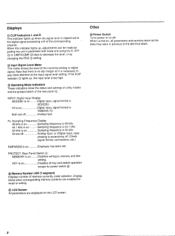
... the master in utility mode the LCD screen will also light up . C) It is possible to memory. L PARAM LINK PER D. Press the MUTE key for the channel you wish to increase or decrease the parameter value under selection will display the output level settings. All knobs are automatically set manually. ® Press the MUTE key again and the LED will turn off and after D/A conversion. Output Level ® The output control knob controls...
... the master in utility mode the LCD screen will also light up . C) It is possible to memory. L PARAM LINK PER D. Press the MUTE key for the channel you wish to increase or decrease the parameter value under selection will display the output level settings. All knobs are automatically set manually. ® Press the MUTE key again and the LED will turn off and after D/A conversion. Output Level ® The output control knob controls...

D2040 Owners Manual Image
Page 19
.... (With the output control knob settings in which you can be used for many different setting. Use the parameter left /right cursor keys the cursor can change the LCD screen "page" to be displayed next time utility mode is used for the channel. Utility Mode The utility mode is entered. The blinking 1" on the LCD screen is executed or confirmed by the ENTER (STORE) key. 0 OUTPUT LEVEL Category Press the...
.... (With the output control knob settings in which you can be used for many different setting. Use the parameter left /right cursor keys the cursor can change the LCD screen "page" to be displayed next time utility mode is used for the channel. Utility Mode The utility mode is entered. The blinking 1" on the LCD screen is executed or confirmed by the ENTER (STORE) key. 0 OUTPUT LEVEL Category Press the...

D2040 Owners Manual Image
Page 20
... parameter edit mode) with AES/EBU. At this time, it is automatically set STORE C) PROGRAM CHANGE TABLE(RS-485 PGM CHANGE) Press the UTILITY key once again and the LCD screen will display the message shown below shows the copying of all parameters from the L side of the recipient RS-485. UTILITY AUDIO SOURCE INPUT:AES/EBU Utility Category Input Format press to copy specific parameter...
... parameter edit mode) with AES/EBU. At this time, it is automatically set STORE C) PROGRAM CHANGE TABLE(RS-485 PGM CHANGE) Press the UTILITY key once again and the LCD screen will display the message shown below shows the copying of all parameters from the L side of the recipient RS-485. UTILITY AUDIO SOURCE INPUT:AES/EBU Utility Category Input Format press to copy specific parameter...

D2040 Owners Manual Image
Page 21
... communication. Use the parameter left/right cursor keys to move to the group number (GRP) and to the device number (DEV), and use the parameter up/down keys to make the desired settings and confirm them with the STORE (ENTER) key. 85485 LOCAL NORM r- (1) RS-485 LOCAL ADDRESS Category Press the UTILITY key once again and the LCD screen will display the...
... communication. Use the parameter left/right cursor keys to move to the group number (GRP) and to the device number (DEV), and use the parameter up/down keys to make the desired settings and confirm them with the STORE (ENTER) key. 85485 LOCAL NORM r- (1) RS-485 LOCAL ADDRESS Category Press the UTILITY key once again and the LCD screen will display the...
D2040 Owners Manual Image
Page 22
giFibraWM . t. heit!set
giFibraWM . t. heit!set
D2040 Owners Manual Image
Page 24
... over 100 meters (320 ft.), it is not set at high impedance. Use only digital audio cables of the following specifications when connecting peripherals through the AES/EBU and RS485 ports: impedance - 90 to make the cable as short as the D2040, data transmission will cause trouble and adversely effect the performance of the cable (connect a resistor between devices, use a conversion box to adapt to the same...
... over 100 meters (320 ft.), it is not set at high impedance. Use only digital audio cables of the following specifications when connecting peripherals through the AES/EBU and RS485 ports: impedance - 90 to make the cable as short as the D2040, data transmission will cause trouble and adversely effect the performance of the cable (connect a resistor between devices, use a conversion box to adapt to the same...
D2040 Owners Manual Image
Page 27
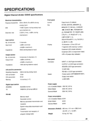
... 48kHz (during balance input) Output section No. of program change table Front panel Control Key Display Output level x 8 (sliders) STORE (ENTER), MEMORY 6, MEMORY V, RECALL, CURSOR -oil, CURSOR 0, PARAMETER 6, PARAMETER V, FADER LINK, UTILITY, L, R, PEQ/D.ATT (1-4), LIMIT/COMP (1-4), DELAY/POLARITY (1-4), FILTER (14), MUTE (1L-4R) 16-character x 2-line LCD unit 7-segment LED (memory number) 8-element LED (mode indicator) 8-element LED x 2 (input level meter) LED x 8 (output clip, indicator) Rear panel Connector Switch INPUT x 2 (XLR type connector) OUTPUT x 8 (XLR type connector...
... 48kHz (during balance input) Output section No. of program change table Front panel Control Key Display Output level x 8 (sliders) STORE (ENTER), MEMORY 6, MEMORY V, RECALL, CURSOR -oil, CURSOR 0, PARAMETER 6, PARAMETER V, FADER LINK, UTILITY, L, R, PEQ/D.ATT (1-4), LIMIT/COMP (1-4), DELAY/POLARITY (1-4), FILTER (14), MUTE (1L-4R) 16-character x 2-line LCD unit 7-segment LED (memory number) 8-element LED (mode indicator) 8-element LED x 2 (input level meter) LED x 8 (output clip, indicator) Rear panel Connector Switch INPUT x 2 (XLR type connector) OUTPUT x 8 (XLR type connector...

D2040 Owners Manual Image
Page 84
No.: Title: Programmer: Date: TYPE PARAMETER PEQ 1 OFF/ON FRQ GAIN PEQ 2 Q OFF/ON FRQ GAIN Q D. YAMAHA I=MCDI4C) USER PROGRAMMING TABLE Mem. ATTENUATOR COMP/LIMIT OFF/ON THRESHOLD RATIO ATTACK RELEASE DELAY CHANNEL OFFSET POLARITY HPF FRQ SLOPE Gain at Cut off Point LPF FRQ SLOPE Gain at Cur off Point OUTPUT LEVEL L-1 L-2 L-3 L-4 OFF • ON OFF • ON OFF • ON OFF •...
No.: Title: Programmer: Date: TYPE PARAMETER PEQ 1 OFF/ON FRQ GAIN PEQ 2 Q OFF/ON FRQ GAIN Q D. YAMAHA I=MCDI4C) USER PROGRAMMING TABLE Mem. ATTENUATOR COMP/LIMIT OFF/ON THRESHOLD RATIO ATTACK RELEASE DELAY CHANNEL OFFSET POLARITY HPF FRQ SLOPE Gain at Cut off Point LPF FRQ SLOPE Gain at Cur off Point OUTPUT LEVEL L-1 L-2 L-3 L-4 OFF • ON OFF • ON OFF • ON OFF •...


