
Owner's Manual
Page 1
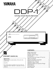
... Unit 4 Speaker System Setup 5 Connections 6 Turning On/Off the Power of This Unit 8 Table of the unit. Serial No.: The serial number is located on the rear of Functions 9 Adjustments Before Operation 10 Playing an AC-3 Source 14 Adjusting Output Levels 14 Adjusting Delays and Dynamic Range ........ 16 Specifications 18 Troubleshooting 18 Block Diagram 19 R C LS DDP-1 RSLFE NATURAL SOUND DIGITAL PROCESSOR L R C LS RS LFE NATURAL SOUND DIGITAL PROCESSOR DDP-1 TEST MODE MENU PARAMETER OWNER'S MANUAL IMPORTANT! Please record the serial number of this Owner's Manual in the...
... Unit 4 Speaker System Setup 5 Connections 6 Turning On/Off the Power of This Unit 8 Table of the unit. Serial No.: The serial number is located on the rear of Functions 9 Adjustments Before Operation 10 Playing an AC-3 Source 14 Adjusting Output Levels 14 Adjusting Delays and Dynamic Range ........ 16 Specifications 18 Troubleshooting 18 Block Diagram 19 R C LS DDP-1 RSLFE NATURAL SOUND DIGITAL PROCESSOR L R C LS RS LFE NATURAL SOUND DIGITAL PROCESSOR DDP-1 TEST MODE MENU PARAMETER OWNER'S MANUAL IMPORTANT! Please record the serial number of this Owner's Manual in the...
Owner's Manual
Page 2
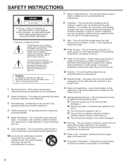
...power cord of the unit should be routed so that may impede the flow of time. 14 Object and Liquid Entry - or B. or E. The exclamation point within the product's enclosure that they are not spilled into the inside of the type described in installation, such as recommended by qualified service... heat. 10 Power Sources - The power-supply cord or the plug has been damaged; The unit has been exposed to operate normally or exhibits a marked change in a wet basement, or near water - NO USER-SERVICEABLE PARTS INSIDE. The unit should not be used only with arrowhead...
...power cord of the unit should be routed so that may impede the flow of time. 14 Object and Liquid Entry - or B. or E. The exclamation point within the product's enclosure that they are not spilled into the inside of the type described in installation, such as recommended by qualified service... heat. 10 Power Sources - The power-supply cord or the plug has been damaged; The unit has been exposed to operate normally or exhibits a marked change in a wet basement, or near water - NO USER-SERVICEABLE PARTS INSIDE. The unit should not be used only with arrowhead...

Owner's Manual
Page 3
... to follow instructions could void your sensitive hearing. Utilize power outlets that lets the sound come through loud and clear without affecting your FCC authorization to use force on switches, controls or connection wires. If the antenna lead-in is 300 ohm ribbon lead, change the lead-in to other equipment. Avoid sources of radio or TV interference, relocate/reorient the antenna. Cable/s supplied with...
... to follow instructions could void your sensitive hearing. Utilize power outlets that lets the sound come through loud and clear without affecting your FCC authorization to use force on switches, controls or connection wires. If the antenna lead-in is 300 ohm ribbon lead, change the lead-in to other equipment. Avoid sources of radio or TV interference, relocate/reorient the antenna. Cable/s supplied with...
Owner's Manual
Page 4
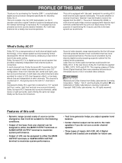
... Dolby Pro Logic that is an ideal choice for sending AC-3 multi-channel audio signals individually. The ongoing release of LFE can be suitable for future use. 4 The audio amplifier or receiver must have "discrete" input terminals to maximize system performance. • Test tone generator helps you adjust speaker level balance. • Center channel output can be assigned to either the MAIN OUTPUT terminals or SUBWOOFER OUTPUT terminal to receive the signals from Dolby Laboratories Licensing Corporation. Dolby Surround AC-3 is a home audio...
... Dolby Pro Logic that is an ideal choice for sending AC-3 multi-channel audio signals individually. The ongoing release of LFE can be suitable for future use. 4 The audio amplifier or receiver must have "discrete" input terminals to maximize system performance. • Test tone generator helps you adjust speaker level balance. • Center channel output can be assigned to either the MAIN OUTPUT terminals or SUBWOOFER OUTPUT terminal to receive the signals from Dolby Laboratories Licensing Corporation. Dolby Surround AC-3 is a home audio...

Owner's Manual
Page 5
... it is ideal to use high performance models that includes the RX-V2090, connect the subwoofer to the "LOW PASS" terminal of the RX-V2090. Center: Precisely between the main speakers. (To avoid interference with the full system. In doing so, the overall adjustment of speaker output levels including the subwoofer can enjoy AC-3 effect without a center speaker Main L Main R Surround L Surround R Surround L Surround R Set the center channel mode (C2. Nearly six...
... it is ideal to use high performance models that includes the RX-V2090, connect the subwoofer to the "LOW PASS" terminal of the RX-V2090. Center: Precisely between the main speakers. (To avoid interference with the full system. In doing so, the overall adjustment of speaker output levels including the subwoofer can enjoy AC-3 effect without a center speaker Main L Main R Surround L Surround R Surround L Surround R Set the center channel mode (C2. Nearly six...
Owner's Manual
Page 6
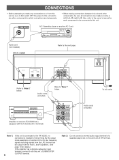
... INPUT AC-3 DIGITAL OPTICAL COAXIAL OUTPUT MAIN CENTER SURROUND SUBWOOFER Refer to "Note 1" below . Audio cords (included) Refer to "Note 2" below . Note 2) Do not connect a normal audio output terminal of a laserdisc player etc. to this terminal. To AC outlet Amplifier or receiver (RX-V2090 etc.) equipped with this unit's SUBWOOFER 6 OUTPUT terminal. Also, refer to this unit. model) Refer to R. By the output mode selections on function C2 to C5, low frequency signals including signals from the LFE channel...
... INPUT AC-3 DIGITAL OPTICAL COAXIAL OUTPUT MAIN CENTER SURROUND SUBWOOFER Refer to "Note 1" below . Audio cords (included) Refer to "Note 2" below . Note 2) Do not connect a normal audio output terminal of a laserdisc player etc. to this terminal. To AC outlet Amplifier or receiver (RX-V2090 etc.) equipped with this unit's SUBWOOFER 6 OUTPUT terminal. Also, refer to this unit. model) Refer to R. By the output mode selections on function C2 to C5, low frequency signals including signals from the LFE channel...
Owner's Manual
Page 7
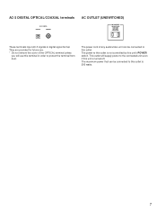
... input AC-3 signals in order to protect the terminal from dust. They are provided for future use. * Do not remove the cover of any audio/video unit can be connected to the connected unit even if this outlet is 200 watts. 7 This outlet will use this terminal in digital signal format. The maximum power that can be connected to this outlet is turned off. AC-3 DIGITAL OPTICAL/COAXIAL...
... input AC-3 signals in order to protect the terminal from dust. They are provided for future use. * Do not remove the cover of any audio/video unit can be connected to the connected unit even if this outlet is 200 watts. 7 This outlet will use this terminal in digital signal format. The maximum power that can be connected to this outlet is turned off. AC-3 DIGITAL OPTICAL/COAXIAL...
Owner's Manual
Page 8
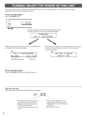
... POWER switch so that the display turns off. ex.) AC- 3 DECODING fs=48k ch : 3/2 Sampling frequencies Audio code When there is no data input, or data other than AC-3 is shown. About the Audio Code Audio code shows the formation and the number of this message for connection is input to this unit, the input terminal on the rear of channels. TEST MODE MENU PARAMETER The display turns on and shows this unit used...
... POWER switch so that the display turns off. ex.) AC- 3 DECODING fs=48k ch : 3/2 Sampling frequencies Audio code When there is no data input, or data other than AC-3 is shown. About the Audio Code Audio code shows the formation and the number of this message for connection is input to this unit, the input terminal on the rear of channels. TEST MODE MENU PARAMETER The display turns on and shows this unit used...
Owner's Manual
Page 9
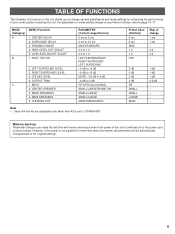
.../SUBWOOFER Preset value (Position) 0 ms 5 ms MAX 1.0 1.0 OFF Step of change several adjustments and mode settings for enhancing the performance of this unit. MODE (Category) A B MENU (Function) 1. MAIN SPEAKERS 5. Memory back up Parameter changes you to change 1 ms 1 ms - 0.2 0.2 - 0 dB 0 dB 0 dB 0 dB RF SMALL SMALL LARGE MAIN 1 dB 1 dB 1 dB 0.5 dB - - - - - TEST: OFF/ON 2. CENTER SPEAKER 3. REAR SPEAKERS 4. DYNAMIC RANGE 4. RIGHT SURROUND LEVEL 4. HIGH LEVEL CUT SCALE* 5. SURROUND DELAY 3. LEFT SURROUND LEVEL 3. INPUT 2. CENTER DELAY 2. LFE...
.../SUBWOOFER Preset value (Position) 0 ms 5 ms MAX 1.0 1.0 OFF Step of change several adjustments and mode settings for enhancing the performance of this unit. MODE (Category) A B MENU (Function) 1. MAIN SPEAKERS 5. Memory back up Parameter changes you to change 1 ms 1 ms - 0.2 0.2 - 0 dB 0 dB 0 dB 0 dB RF SMALL SMALL LARGE MAIN 1 dB 1 dB 1 dB 0.5 dB - - - - - TEST: OFF/ON 2. CENTER SPEAKER 3. REAR SPEAKERS 4. DYNAMIC RANGE 4. RIGHT SURROUND LEVEL 4. HIGH LEVEL CUT SCALE* 5. SURROUND DELAY 3. LEFT SURROUND LEVEL 3. INPUT 2. CENTER DELAY 2. LFE...
Owner's Manual
Page 10
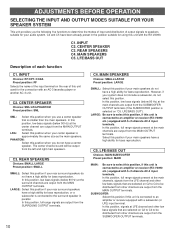
INPUT C2. REAR SPEAKERS C4. LFE/BASS OUT Description of this unit used for bass reproduction. MAIN SPEAKERS Choices: SMALL/LARGE Preset position: LARGE SMALL: Select this position, full range signals present at the main channels, signals from the LFE channel and other channels are output from the SUBWOOFER OUTPUT terminals. 10 In this position if your rear surround speakers have a high ability for bass reproduction, or a subwoofer is connected to an amplifier or receiver equipped with a subwoofer (or LFE) input terminal...
INPUT C2. REAR SPEAKERS C4. LFE/BASS OUT Description of this unit used for bass reproduction. MAIN SPEAKERS Choices: SMALL/LARGE Preset position: LARGE SMALL: Select this position, full range signals present at the main channels, signals from the LFE channel and other channels are output from the SUBWOOFER OUTPUT terminals. 10 In this position if your rear surround speakers have a high ability for bass reproduction, or a subwoofer is connected to an amplifier or receiver equipped with a subwoofer (or LFE) input terminal...

Owner's Manual
Page 11
INPU RF O 5 Repeat step 3 and 4 to change the selection appears on the display. INPUT RF OPT. COAX. Note If there is no operation for about 5 seconds, the original message will be restored on the display. INPUT RF OPT. C1. C1. C1. COAX. 11 Method of changing selections TEST MODE MENU PARAMETER 1 23 4 1 Turn the power on. 2 MODE Press once or more until "C" appears on the left...
INPU RF O 5 Repeat step 3 and 4 to change the selection appears on the display. INPUT RF OPT. COAX. Note If there is no operation for about 5 seconds, the original message will be restored on the display. INPUT RF OPT. C1. C1. C1. COAX. 11 Method of changing selections TEST MODE MENU PARAMETER 1 23 4 1 Turn the power on. 2 MODE Press once or more until "C" appears on the left...
Owner's Manual
Page 12
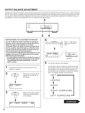
... appears on the display. RIGHT SURROUND LEFT SURROUND B1. TEST : OFF ON Continued 12 OUTPUT BALANCE ADJUSTMENT Adjusting the output level balance among the left main, center, right main and surround channels for Dolby Pro Logic on the RX-V2090, refer to a minimum level on the amplifier or receiver. 2 MODE Press once or more until "B" appears on the left side of the display. Before making the adjustment on the amplifier (or receiver) connected with this...
... appears on the display. RIGHT SURROUND LEFT SURROUND B1. TEST : OFF ON Continued 12 OUTPUT BALANCE ADJUSTMENT Adjusting the output level balance among the left main, center, right main and surround channels for Dolby Pro Logic on the RX-V2090, refer to a minimum level on the amplifier or receiver. 2 MODE Press once or more until "B" appears on the left side of the display. Before making the adjustment on the amplifier (or receiver) connected with this...
Owner's Manual
Page 13
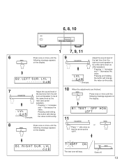
... and holding the button will change the value continuously. MENU Press once or more until the MENU following message appears on the display. B1. TEST MODE Goes off. 13 Changes. 7 Adjust the sound level of PARAMETER the test tone from the left surround speaker to be at the same level as the main and center speakers. * Pressing "+" increases and "-" decreases the . LVL . .0 d B value. ON MODE B3. 6, 8, 10 TEST MODE MENU PARAMETER 1 7, 9, 11...
... and holding the button will change the value continuously. MENU Press once or more until the MENU following message appears on the display. B1. TEST MODE Goes off. 13 Changes. 7 Adjust the sound level of PARAMETER the test tone from the left surround speaker to be at the same level as the main and center speakers. * Pressing "+" increases and "-" decreases the . LVL . .0 d B value. ON MODE B3. 6, 8, 10 TEST MODE MENU PARAMETER 1 7, 9, 11...

Owner's Manual
Page 14
... input mode setting on the amplifier to the "5-ch discrete AC-3 input". * For the RX-V2090, press the LD/TV button on the front panel of the RX-V2090 so that "5 CH DISCRT" appears on the display. (Refer to the section "Dolby Surround AC-3" of the RX-V2090's manual.) 4 Play an AC-3 source on the AC-3 unit. 5 Turn up the volume on the amplifier. 6 If desired, adjust output levels, delays...
... input mode setting on the amplifier to the "5-ch discrete AC-3 input". * For the RX-V2090, press the LD/TV button on the front panel of the RX-V2090 so that "5 CH DISCRT" appears on the display. (Refer to the section "Dolby Surround AC-3" of the RX-V2090's manual.) 4 Play an AC-3 source on the AC-3 unit. 5 Turn up the volume on the amplifier. 6 If desired, adjust output levels, delays...
Owner's Manual
Page 15
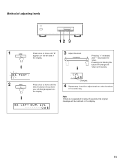
... there is no operation for about 5 seconds, the original message will change appears on other functions in the same way. LEFT SUR. LVL . .0 d B Changes. 4 Repeat step 2 and 3 to adjust levels on the display. Pressing and holding the button will be restored on the display. 15 B1. PARAMETER Pressing "+" increases and "-" decreases the value. Method of adjusting levels TEST MODE MENU PARAMETER 12 3 1 MODE Press once...
... there is no operation for about 5 seconds, the original message will change appears on other functions in the same way. LEFT SUR. LVL . .0 d B Changes. 4 Repeat step 2 and 3 to adjust levels on the display. Pressing and holding the button will be restored on the display. 15 B1. PARAMETER Pressing "+" increases and "-" decreases the value. Method of adjusting levels TEST MODE MENU PARAMETER 12 3 1 MODE Press once...
Owner's Manual
Page 16
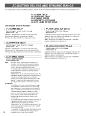
... to a source in a high output level in 1 ms step) Preset value: 0 ms Adjusts the delay between the main sounds (at the main channels) and dialog etc. (at the surround channels). The larger the value, the range is generated. SURROUND DELAY A3. LOW LEVEL BOOST SCALE Description of source. CENTER DELAY Control range: 0 ms to reduce an original sound track's dynamic range for a home audio format by "compressing" the data. A3. Note: This function is available...
... to a source in a high output level in 1 ms step) Preset value: 0 ms Adjusts the delay between the main sounds (at the main channels) and dialog etc. (at the surround channels). The larger the value, the range is generated. SURROUND DELAY A3. LOW LEVEL BOOST SCALE Description of source. CENTER DELAY Control range: 0 ms to reduce an original sound track's dynamic range for a home audio format by "compressing" the data. A3. Note: This function is available...
Owner's Manual
Page 17
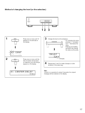
... way. DELAY . . . .0 m s Changes. 4 Repeat step 2 and 3 to make changes on the display. 17 CENT .. 2 MENU Press once or more until the title of the display. A1. A1. Pressing and holding the button will change appears on the display. 3 Change the level (or the selection). * For changing the value, PARAMETER pressing "+" increases and "-" decreases the value. Method of changing the level (or the selection) TEST MODE MENU PARAMETER 12 3 1 MODE Press...
... way. DELAY . . . .0 m s Changes. 4 Repeat step 2 and 3 to make changes on the display. 17 CENT .. 2 MENU Press once or more until the title of the display. A1. A1. Pressing and holding the button will change appears on the display. 3 Change the level (or the selection). * For changing the value, PARAMETER pressing "+" increases and "-" decreases the value. Method of changing the level (or the selection) TEST MODE MENU PARAMETER 12 3 1 MODE Press...
Owner's Manual
Page 18
... too great. Whole sound level is low, even though the volume is increased on when the POWER switch is low. The setting of the rear surround speakers is not completely inserted. Make output mode selections suitable for each channel (MAIN, CENTER or REAR) is too close to MUTE. Increase the level. SPECIFICATIONS Output Level/Output Impedance MAIN L/R, CENTER, SURROUND L/R 1 kHz, 0 dB INPUT 2V/1.2 kΩ SUBWOOFER 50 Hz, 0 dB INPUT 6V/1.2 kΩ Input Impedance (RF, COAXIAL 75Ω Frequency Response MAIN L/R, CENTER, SURROUND L/R (LARGE) 20...
... too great. Whole sound level is low, even though the volume is increased on when the POWER switch is low. The setting of the rear surround speakers is not completely inserted. Make output mode selections suitable for each channel (MAIN, CENTER or REAR) is too close to MUTE. Increase the level. SPECIFICATIONS Output Level/Output Impedance MAIN L/R, CENTER, SURROUND L/R 1 kHz, 0 dB INPUT 2V/1.2 kΩ SUBWOOFER 50 Hz, 0 dB INPUT 6V/1.2 kΩ Input Impedance (RF, COAXIAL 75Ω Frequency Response MAIN L/R, CENTER, SURROUND L/R (LARGE) 20...

Owner's Manual
Page 19
C1. CENTER LARGE C SPEAKER SMALL PHANTOM -4.5dB LS C3. OUTPUT TRIM BLOCK DIAGRAM 19 AC-3 RF DEMODULATOR OPTICAL COAXIAL AC-3 DECODER DDP-1 BLOCK DIAGRAM 20bit D/A 20bit D/A 20bit D/A C4. LFE MIX LEVEL +10dB -4.5dB -4.5dB HPF 2nd order HPF 2nd order MAIN L MAIN R HPF 2nd order HPF 2nd order HPF 2nd order B2. INPUT B5. RIGHT SUR LEVEL LPF 4th order LPF 4th order MAIN SUBWOOFER CROSSOVER 90Hz C5. MAIN SPEAKERS L -3dB R LARGE SMALL C2. LFE/BASS OUT SUBWOOFER LEFT SUR LEVEL CENTER SURROUND L SURROUND R B3. REAR SPEAKERS LARGE SMALL RS LFE B4.
C1. CENTER LARGE C SPEAKER SMALL PHANTOM -4.5dB LS C3. OUTPUT TRIM BLOCK DIAGRAM 19 AC-3 RF DEMODULATOR OPTICAL COAXIAL AC-3 DECODER DDP-1 BLOCK DIAGRAM 20bit D/A 20bit D/A 20bit D/A C4. LFE MIX LEVEL +10dB -4.5dB -4.5dB HPF 2nd order HPF 2nd order MAIN L MAIN R HPF 2nd order HPF 2nd order HPF 2nd order B2. INPUT B5. RIGHT SUR LEVEL LPF 4th order LPF 4th order MAIN SUBWOOFER CROSSOVER 90Hz C5. MAIN SPEAKERS L -3dB R LARGE SMALL C2. LFE/BASS OUT SUBWOOFER LEFT SUR LEVEL CENTER SURROUND L SURROUND R B3. REAR SPEAKERS LARGE SMALL RS LFE B4.
Owner's Manual
Page 20
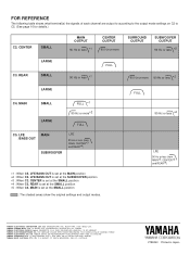
...or more SURROUND OUTPUT SUBWOOFER OUTPUT 90 Hz or less *2 C3. OF GERMANY YAMAHA ELECTRONIQUE FRANCE S.A. REAR LARGE SMALL 90 Hz or less *1 FULL 90 Hz or more 90 Hz or less *2 LARGE C4. LFE MAIN /BASS OUT SUBWOOFER LFE 90 Hz or less (from MAIN*5, CENTER*3 and REAR*4) YAMAHA ELECTRONICS CORPORATION... less *2 LFE 90 Hz or less (from MAIN, CENTER*3 and REAR*4) *1 : When C5. FOR REFERENCE The following table shows what terminal(s) the signals of each channel are output to according to the output mode settings on C2 to C5. (See page 10 for details.) C2. CENTER is set at the...
...or more SURROUND OUTPUT SUBWOOFER OUTPUT 90 Hz or less *2 C3. OF GERMANY YAMAHA ELECTRONIQUE FRANCE S.A. REAR LARGE SMALL 90 Hz or less *1 FULL 90 Hz or more 90 Hz or less *2 LARGE C4. LFE MAIN /BASS OUT SUBWOOFER LFE 90 Hz or less (from MAIN*5, CENTER*3 and REAR*4) YAMAHA ELECTRONICS CORPORATION... less *2 LFE 90 Hz or less (from MAIN, CENTER*3 and REAR*4) *1 : When C5. FOR REFERENCE The following table shows what terminal(s) the signals of each channel are output to according to the output mode settings on C2 to C5. (See page 10 for details.) C2. CENTER is set at the...


