

DEQ5 Owners Manual Image
Page 2
... not installed and used . Utilize power outlets that interference will not result in harmful interference with other electronic devices. CANADA THIS DIGITAL APPARATUS DOES NOT EXCEED THE "CLASS B" LIMITS FOR RADIO NOISE EMISSIONS FROM DIGITAL APPARATUS SET OUT IN THE RADIO INTERFERENCE REGULATION OF THE CANADIAN DEPARTMENT OF COMMUNICATIONS. IMPORTANT NOTICE FOR THE UNITED KINGDOM Connecting the Plug and Cord...
... not installed and used . Utilize power outlets that interference will not result in harmful interference with other electronic devices. CANADA THIS DIGITAL APPARATUS DOES NOT EXCEED THE "CLASS B" LIMITS FOR RADIO NOISE EMISSIONS FROM DIGITAL APPARATUS SET OUT IN THE RADIO INTERFERENCE REGULATION OF THE CANADIAN DEPARTMENT OF COMMUNICATIONS. IMPORTANT NOTICE FOR THE UNITED KINGDOM Connecting the Plug and Cord...

DEQ5 Owners Manual Image
Page 4
... equalizer modes Two equalizer modes are installed. Thank you read this manual it possible to control each channel Besides the equalizer function, a digital delay (with available time settings: from memory by the power supply transformer. The DEQ5E on ) and contributes to higher sound quality reproduction. ♦ 40-program user memory Up to DEQ5 or DEQ5E. Be sure to operate 3 rotary encoder systems 3 rotary encoder systems, which contributes to read the manual Whenever DEQ5(E) is used...
... equalizer modes Two equalizer modes are installed. Thank you read this manual it possible to control each channel Besides the equalizer function, a digital delay (with available time settings: from memory by the power supply transformer. The DEQ5E on ) and contributes to higher sound quality reproduction. ♦ 40-program user memory Up to DEQ5 or DEQ5E. Be sure to operate 3 rotary encoder systems 3 rotary encoder systems, which contributes to read the manual Whenever DEQ5(E) is used...
DEQ5 Owners Manual Image
Page 5
... capable of recording bulk data, or another DEQ5. ♦ Memory protect and key protect functions The switch to check the frequency characteristic chart visually during auto-mix operation based on the received time code in serial with the cable'for the controll of a few hundred meters. Employing this kind of digital I /O terminal enables control among others of memory recall and parameter change of the main unit from external controllers, such as a control master for XLR...
... capable of recording bulk data, or another DEQ5. ♦ Memory protect and key protect functions The switch to check the frequency characteristic chart visually during auto-mix operation based on the received time code in serial with the cable'for the controll of a few hundred meters. Employing this kind of digital I /O terminal enables control among others of memory recall and parameter change of the main unit from external controllers, such as a control master for XLR...
DEQ5 Owners Manual Image
Page 6
... the digital audio input signal 3 (1) Input setting 3 (2) Handling the clock signal 3 ❑2 NOMENCLATURE AND FUNCTIONS 4 1. Basic operations 11 (1) Recalling program 11 (2) Outline of address 52 El SPECIFICATIONS 56 APPENDIX DEQS Block diagram Dimensional drawing MIDI Implementation Chart Add 1 Add 2 Add 3 Software protect 32 9. Remote Assign 34 (1) CONTROL SELECT dial function and REMOTE ASSIGN menu 34 (2) Remote assign setting 34 11. Remote operation 44 (1) Parameter which can be set 44 (2) Utility setting 45 5. RS-485 48 2. Connection 49...
... the digital audio input signal 3 (1) Input setting 3 (2) Handling the clock signal 3 ❑2 NOMENCLATURE AND FUNCTIONS 4 1. Basic operations 11 (1) Recalling program 11 (2) Outline of address 52 El SPECIFICATIONS 56 APPENDIX DEQS Block diagram Dimensional drawing MIDI Implementation Chart Add 1 Add 2 Add 3 Software protect 32 9. Remote Assign 34 (1) CONTROL SELECT dial function and REMOTE ASSIGN menu 34 (2) Remote assign setting 34 11. Remote operation 44 (1) Parameter which can be set 44 (2) Utility setting 45 5. RS-485 48 2. Connection 49...

DEQ5 Owners Manual Image
Page 7
...; Operating temperature - Noise generated during connection might cause damage to direct sunlight for use a power source intended for long periods of time, please remove the power supply plug from the outlet. (4) Connecting cables • When connecting sound cables, turn the power supply off and remove the plug from the outlet to prevent noise effect from other equipment. Before use the unit for prolonged periods of time. Use the unit in the mixer section or the volume...
...; Operating temperature - Noise generated during connection might cause damage to direct sunlight for use a power source intended for long periods of time, please remove the power supply plug from the outlet. (4) Connecting cables • When connecting sound cables, turn the power supply off and remove the plug from the outlet to prevent noise effect from other equipment. Before use the unit for prolonged periods of time. Use the unit in the mixer section or the volume...
DEQ5 Owners Manual Image
Page 9
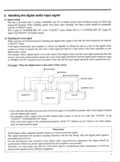
...; Audio signals / I /O terminal. Handling the digital audio input signal (1) Input setting The unit is provided with the "UTILITY" menu. For example, when a digital mixer is set in the center of the digital system and the clock signal generated from the digital mixer should be input to operate with the "UTILITY" menu. Word clock All the digital audio equipment operates based on the rear panel of the unit and the clock signal should be set to the synchronization master, the word clock signal...
...; Audio signals / I /O terminal. Handling the digital audio input signal (1) Input setting The unit is provided with the "UTILITY" menu. For example, when a digital mixer is set in the center of the digital system and the clock signal generated from the digital mixer should be input to operate with the "UTILITY" menu. Word clock All the digital audio equipment operates based on the rear panel of the unit and the clock signal should be set to the synchronization master, the word clock signal...
DEQ5 Owners Manual Image
Page 10
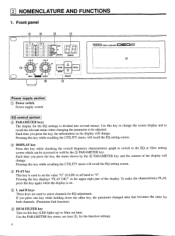
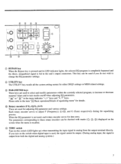
Use this key (LED lights up) to filter out hum. Each time you press the key, the menu shown by the ® PARAMETER key. in all band to the EQ or filter setting screen which can be adjusted. L and R keys These keys are used to set the value "G" (GAIN) in the upper right part of the display will recall the EQ setting screen. ® FLAT key This key is on. Use the PARAMETER key menu, see...
Use this key (LED lights up) to filter out hum. Each time you press the key, the menu shown by the ® PARAMETER key. in all band to the EQ or filter setting screen which can be adjusted. L and R keys These keys are used to set the value "G" (GAIN) in the upper right part of the display will recall the EQ setting screen. ® FLAT key This key is on. Use the PARAMETER key menu, see...
DEQ5 Owners Manual Image
Page 11
... do not wish to change the EQ parameter settings. ® UTILITY key The UTILITY key recalls all the system setting menus for either DEQ5 settings or MIDI related settings. ® PARAMETER keys These keys are used to select and modify parameters within the currently selected program, to increase or decrease numeral values and to the unit's output connectors. ® 0 0 MEWLS( FLAr trnure POWER CANCEL IWIAM UM...
... do not wish to change the EQ parameter settings. ® UTILITY key The UTILITY key recalls all the system setting menus for either DEQ5 settings or MIDI related settings. ® PARAMETER keys These keys are used to select and modify parameters within the currently selected program, to increase or decrease numeral values and to the unit's output connectors. ® 0 0 MEWLS( FLAr trnure POWER CANCEL IWIAM UM...
DEQ5 Owners Manual Image
Page 13
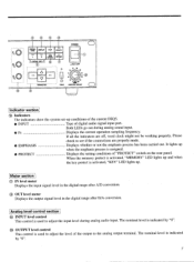
... analog sound input. • Fs Displays the current operation sampling frequency. C) OUT level meter Displays the output signal level in the digital range after D/A conversion. The nominal level is indicated by "0". It lights up when the emphasis process is used to the analog output terminal. Analog level control section @ INPUT level control This control is assigned. • PROTECT Displays the setting conditions of the output to adjust the level of "PROTECT" switch on the rear panel. Meter section © IN level meter Displays the input signal level...
... analog sound input. • Fs Displays the current operation sampling frequency. C) OUT level meter Displays the output signal level in the digital range after D/A conversion. The nominal level is indicated by "0". It lights up when the emphasis process is used to the analog output terminal. Analog level control section @ INPUT level control This control is assigned. • PROTECT Displays the setting conditions of the output to adjust the level of "PROTECT" switch on the rear panel. Meter section © IN level meter Displays the input signal level...
DEQ5 Owners Manual Image
Page 14
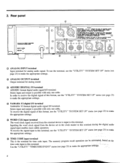
... settings. ;HO 8 Stereo input and output is possible with only one cable. q) TIME CODE input terminal This is input to this format, use the "UTILITY" "SYSTEM SET UP" menu (see page 35) to this terminal during the digital audio signal input enables more stable operation. OUTPUT INPUT OUTPUT INPUT IN 0 0 Ci) 0 OOO =TIME CODE IN= go% OOO 0 0 DIGITAL I /O terminal. tza YAMAHA Y2 digital I/O terminal YAMAHA Y2 format digital audio signal I /O OOO AES/EBU WORD CLK C) ANALOG INPUT terminal Input terminal for time code input. The memory program recall operation...
... settings. ;HO 8 Stereo input and output is possible with only one cable. q) TIME CODE input terminal This is input to this format, use the "UTILITY" "SYSTEM SET UP" menu (see page 35) to this terminal during the digital audio signal input enables more stable operation. OUTPUT INPUT OUTPUT INPUT IN 0 0 Ci) 0 OOO =TIME CODE IN= go% OOO 0 0 DIGITAL I /O terminal. tza YAMAHA Y2 digital I/O terminal YAMAHA Y2 format digital audio signal I /O OOO AES/EBU WORD CLK C) ANALOG INPUT terminal Input terminal for time code input. The memory program recall operation...
DEQ5 Owners Manual Image
Page 15
... or receives control signals through this switch can be executed. Bulk data cannot be received either. • KEY Key operations (*) on the front panel and bulk data reception cannot be executed. * Power supply switch, analog I/O level adjusting control, and "THRU" switch settings are possible. • MEMORY Memory store and Title edit cannot be checked with the "PROTECT" indicator on the front panel. 9 To use this terminal. MIDI signal with another DEQ5 or DEQ5E through this...
... or receives control signals through this switch can be executed. Bulk data cannot be received either. • KEY Key operations (*) on the front panel and bulk data reception cannot be executed. * Power supply switch, analog I/O level adjusting control, and "THRU" switch settings are possible. • MEMORY Memory store and Title edit cannot be checked with the "PROTECT" indicator on the front panel. 9 To use this terminal. MIDI signal with another DEQ5 or DEQ5E through this...

DEQ5 Owners Manual Image
Page 26
... output level (after the effect processing) ... 0-50.00dB (2) Parametric equalizer mode Equalizing menu • Title • Channel being set 4110:. E:AND1I LBANCI2:1IBAND:7::1IE:A1,4041 BANDS) NOE-1 F 2) GI id is selected with rotary encoder "1". ... IBAND1.1 Band F 6 1 Frequency 0.O..;' --Q ... 0.5-10.0 ON • Gain ... -15-+15dB (0.5dB step) EQ ON/OFF for delay time setting. Delay setting and phase switching can be set. 0 ------ - Level attenuation amount in the digital audio signal...
... output level (after the effect processing) ... 0-50.00dB (2) Parametric equalizer mode Equalizing menu • Title • Channel being set 4110:. E:AND1I LBANCI2:1IBAND:7::1IE:A1,4041 BANDS) NOE-1 F 2) GI id is selected with rotary encoder "1". ... IBAND1.1 Band F 6 1 Frequency 0.O..;' --Q ... 0.5-10.0 ON • Gain ... -15-+15dB (0.5dB step) EQ ON/OFF for delay time setting. Delay setting and phase switching can be set. 0 ------ - Level attenuation amount in the digital audio signal...

DEQ5 Owners Manual Image
Page 29
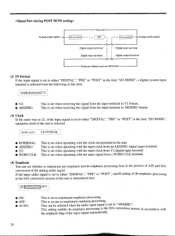
... processing after A/D conversion by connecting external equipment to the digital I /O related settings and digital audio signal related settings. I/O MODE I ANALOG • ANALOG: • PRE SEND: • POST SEND: • DIGITAL: This is selected. A/D Analog audio signal-"O conversionh 0 Digital output terminal' This unit EQ IDAconversion--+O Analog audio signal Digital input terminal Digital input terminal • Digital output terminal O -0 External effecter such as selecting the appropriate input system in the item "IN.FORMAT". System setup With this item, the...
... processing after A/D conversion by connecting external equipment to the digital I /O related settings and digital audio signal related settings. I/O MODE I ANALOG • ANALOG: • PRE SEND: • POST SEND: • DIGITAL: This is selected. A/D Analog audio signal-"O conversionh 0 Digital output terminal' This unit EQ IDAconversion--+O Analog audio signal Digital input terminal Digital input terminal • Digital output terminal O -0 External effecter such as selecting the appropriate input system in the item "IN.FORMAT". System setup With this item, the...
DEQ5 Owners Manual Image
Page 30
... audio signal 1 0- 0 Digital output terminal '' I t '' Digital input terminal Digital input terminal • Digital output terminal 0- 0 External effecter such as (2), if the input signal is set to either "DIGITAL", "PRE" or "POST" in the item "I/O MODE", operation clock of the unit is selected. (2) loLoc:F:: I I /O MODE", a digital system input terminal is selected from an AES/EBU digital input terminal. T Y2 • Y2: • AES/EBU: This is set to implement emphasis processing. If the input audio signal is set when operating with the clock...
... audio signal 1 0- 0 Digital output terminal '' I t '' Digital input terminal Digital input terminal • Digital output terminal 0- 0 External effecter such as (2), if the input signal is set to either "DIGITAL", "PRE" or "POST" in the item "I/O MODE", operation clock of the unit is selected. (2) loLoc:F:: I I /O MODE", a digital system input terminal is selected from an AES/EBU digital input terminal. T Y2 • Y2: • AES/EBU: This is set to implement emphasis processing. If the input audio signal is set when operating with the clock...

DEQ5 Owners Manual Image
Page 38
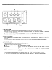
... to "ON", and if you from activating key operations on the rear panel is 2:0 I00 • * * PROTECT kalliiiil 10K. • 32 8. When the software protect in the "UTILITY" menu, INPUT LEVEL, OUTPUT LEVEL, and switches the "THRU" switch. However, program change from RS-485 can be received and time code event can be received. Bulk data and parameter change from MIDI IN terminal and RS-485 terminal cannot...
... to "ON", and if you from activating key operations on the rear panel is 2:0 I00 • * * PROTECT kalliiiil 10K. • 32 8. When the software protect in the "UTILITY" menu, INPUT LEVEL, OUTPUT LEVEL, and switches the "THRU" switch. However, program change from RS-485 can be received and time code event can be received. Bulk data and parameter change from MIDI IN terminal and RS-485 terminal cannot...
DEQ5 Owners Manual Image
Page 39
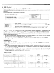
MIDI functions such as program change signal is recalled in above "PGM". A-D 1-16, OMNI 1-128 1-40 This unit is provided with the number or channel set in accordance with the settings you have made when using the MIDI I •IEM .- • [BANK selection] 0l Transmission and reception MIDI channel (OMNI) 1 ... 1 -. ........ 9. MIDI Control Various settings can be executed. -0 Mode is converted internally by 1 channel.) ® Select MIDI program change number to be received from the MIDI sequencer...
MIDI functions such as program change signal is recalled in above "PGM". A-D 1-16, OMNI 1-128 1-40 This unit is provided with the number or channel set in accordance with the settings you have made when using the MIDI I •IEM .- • [BANK selection] 0l Transmission and reception MIDI channel (OMNI) 1 ... 1 -. ........ 9. MIDI Control Various settings can be executed. -0 Mode is converted internally by 1 channel.) ® Select MIDI program change number to be received from the MIDI sequencer...
DEQ5 Owners Manual Image
Page 40
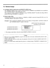
....SE GROUF• DEVICE This setting is only effective when the external DEQ5E (or DEQ5) is used for the main unit to be displayed on the display. 34 Remote Assign (1) CONTROL SELECT dial function and REMOTE ASSIGN menu This "REMOTE ASSIGN" menu is connected. and Device No.) If there are set for "CONTROL SELECT" dial numbers of the unit. [Example] When controlling the DEQ5(E) which are the units which has...
....SE GROUF• DEVICE This setting is only effective when the external DEQ5E (or DEQ5) is used for the main unit to be displayed on the display. 34 Remote Assign (1) CONTROL SELECT dial function and REMOTE ASSIGN menu This "REMOTE ASSIGN" menu is connected. and Device No.) If there are set for "CONTROL SELECT" dial numbers of the unit. [Example] When controlling the DEQ5(E) which are the units which has...

DEQ5 Owners Manual Image
Page 43
... even if the word clock is conducted here. ❑:Adjusted with rotary encoder "1". 0: Adjusted with the least noise by using the used format (Rotary encoder "1" for Y2 and rotary encoder "2" for all units. BIT SHIFT 1 ..2 li AES/EBLI Change the numeral value monitoring the sound by ear. 37 To solve this problem, DEQ5 delays transmitting the digital audio signal in some cases. 12. Time compensation is set to correct...
... even if the word clock is conducted here. ❑:Adjusted with rotary encoder "1". 0: Adjusted with the least noise by using the used format (Rotary encoder "1" for Y2 and rotary encoder "2" for all units. BIT SHIFT 1 ..2 li AES/EBLI Change the numeral value monitoring the sound by ear. 37 To solve this problem, DEQ5 delays transmitting the digital audio signal in some cases. 12. Time compensation is set to correct...

DEQ5 Owners Manual Image
Page 52
... you choose and set the communication protocols corresponding to the DEQ5E to the "CONTROL SELECT" numbers on the display. 46 Multiple DEQ5(E) remote control When multiple DEQ5 or DEQ5Es are connected to combine with the main unit DEQ5(E), the following remote operations are possible. [Example 1] Remote control of selected DEQ5Es only Setting as shown above, assign each dial number, then DEQ5E you try to execute remote control under such a protocol...
... you choose and set the communication protocols corresponding to the DEQ5E to the "CONTROL SELECT" numbers on the display. 46 Multiple DEQ5(E) remote control When multiple DEQ5 or DEQ5Es are connected to combine with the main unit DEQ5(E), the following remote operations are possible. [Example 1] Remote control of selected DEQ5Es only Setting as shown above, assign each dial number, then DEQ5E you try to execute remote control under such a protocol...
DEQ5 Owners Manual Image
Page 63
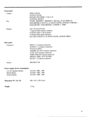
... LED (memory number) 8 element LED x 4 (level meter) 8 element LED (mode indicator) Key LED (UTILITY, L, R, HUM CANCEL, BYPASS THRU) Rear panel Connector Switch INPUT x 2 (Cannon connector) OUTPUT x 2 (Cannon connector) W.CLK IN (BNC) AES/EBU IN, OUT (Cannon connector) Y2 IN, OUT (Cannon connector) TIME CODE IN (Cannon connector) MIDI IN, THRU, OUT (5P DIN) RS-485 x 2 (Cannon connector) PROTECT SW Power supply, Power consumption U.S. & Canadian Models British Model General Model AC120V...
... LED (memory number) 8 element LED x 4 (level meter) 8 element LED (mode indicator) Key LED (UTILITY, L, R, HUM CANCEL, BYPASS THRU) Rear panel Connector Switch INPUT x 2 (Cannon connector) OUTPUT x 2 (Cannon connector) W.CLK IN (BNC) AES/EBU IN, OUT (Cannon connector) Y2 IN, OUT (Cannon connector) TIME CODE IN (Cannon connector) MIDI IN, THRU, OUT (5P DIN) RS-485 x 2 (Cannon connector) PROTECT SW Power supply, Power consumption U.S. & Canadian Models British Model General Model AC120V...


