

Owner's Manual
Page 2
.... NO USER-SERVICEABLE PARTS INSIDE. A polarized plug has two blades with the letter N or coloured BLACK. The wire which is coloured BLUE must be connected to the terminal which is marked with the letter L or coloured RED. (3 wires) receptacles, and the point where they exit from tip-over. 13 Unplug this mains lead are provided for replacement of time. 14...
.... NO USER-SERVICEABLE PARTS INSIDE. A polarized plug has two blades with the letter N or coloured BLACK. The wire which is coloured BLUE must be connected to the terminal which is marked with the letter L or coloured RED. (3 wires) receptacles, and the point where they exit from tip-over. 13 Unplug this mains lead are provided for replacement of time. 14...

Owner's Manual
Page 3
..., do not touch the power cable plug if it from the AC outlet, and remove all musical instruments, audio equipment, and speakers when connecting to the rack mounting instructions on vacation, remove the power plug from the following locations: - For safe operation - WARNING Installation ● Connect this unit's power cord only to an AC outlet of time, such as marked on the power to become wet. Precautions...
..., do not touch the power cable plug if it from the AC outlet, and remove all musical instruments, audio equipment, and speakers when connecting to the rack mounting instructions on vacation, remove the power plug from the following locations: - For safe operation - WARNING Installation ● Connect this unit's power cord only to an AC outlet of time, such as marked on the power to become wet. Precautions...

Owner's Manual
Page 4
... a mobile phone near this product to use this manual are for explanatory purposes only, and may void your FCC authorization to products (KAX-5000) distributed by YAMAHA CORPORATION OF AMERICA. 4 IMPORTANT NOTICE: DO NOT MODIFY THIS UNIT! IMPORTANT: When connecting this unit may induce noise. Always turn the power off when the amplifier is not in the USA...
... a mobile phone near this product to use this manual are for explanatory purposes only, and may void your FCC authorization to products (KAX-5000) distributed by YAMAHA CORPORATION OF AMERICA. 4 IMPORTANT NOTICE: DO NOT MODIFY THIS UNIT! IMPORTANT: When connecting this unit may induce noise. Always turn the power off when the amplifier is not in the USA...

Owner's Manual
Page 5
... YAMAHA KAX-5000, KAX3500 or KAX-2500 power amplifier. Contents Controls and Functions 6 Front Panel 6 Rear Panel 7 Speaker Connections 9 Speaker impedance 9 Wiring 10 Rack Mounting 11 Specifications 12 General Specifications 12 Block Diagram 13 Dimensions 14 Current Draw 14 Troubleshooting 15 5 The TEMP indicator lights up -and sound output is automatically muted-whenever the unit's protective circuitry is suitable for your purchase of applications and installed systems. • The unit offers three operating modes: STEREO (where Channels A and B operate...
... YAMAHA KAX-5000, KAX3500 or KAX-2500 power amplifier. Contents Controls and Functions 6 Front Panel 6 Rear Panel 7 Speaker Connections 9 Speaker impedance 9 Wiring 10 Rack Mounting 11 Specifications 12 General Specifications 12 Block Diagram 13 Dimensions 14 Current Draw 14 Troubleshooting 15 5 The TEMP indicator lights up -and sound output is automatically muted-whenever the unit's protective circuitry is suitable for your purchase of applications and installed systems. • The unit offers three operating modes: STEREO (where Channels A and B operate...

Owner's Manual
Page 6
... amplifier. (2) Adjust the security cover to operate. Controls and Functions ■ Front Panel 2 4 8 13 576 8 1 POWER switch and indicator Press to remove the four attach- To provide protection, the unit will not output any sound from the front and exhaust it into a 4 Ω load). 6 Volume control knobs Each control knob adjusts the volume of the heat sink rises above 1%-indicating that "clipping" has occurred because the signal level...
... amplifier. (2) Adjust the security cover to operate. Controls and Functions ■ Front Panel 2 4 8 13 576 8 1 POWER switch and indicator Press to remove the four attach- To provide protection, the unit will not output any sound from the front and exhaust it into a 4 Ω load). 6 Volume control knobs Each control knob adjusts the volume of the heat sink rises above 1%-indicating that "clipping" has occurred because the signal level...

Owner's Manual
Page 7
... SUB WOOFER LOW CUT OFF Do not use this switch ON, the amplifier adds low-frequency compensation so as follows. The amplifier outputs the frequencies that if you are using BRIDGE or PARALLEL mode, only the Channel A jacks are effective. • XLR-3-31 jack The XLR-3-31 input jacks are wired as to filter out unneeded low or subsonic frequencies. Cutoff frequency 2 ON/OFF switch If you can use any filter. The adjustment range is set to select...
... SUB WOOFER LOW CUT OFF Do not use this switch ON, the amplifier adds low-frequency compensation so as follows. The amplifier outputs the frequencies that if you are using BRIDGE or PARALLEL mode, only the Channel A jacks are effective. • XLR-3-31 jack The XLR-3-31 input jacks are wired as to filter out unneeded low or subsonic frequencies. Cutoff frequency 2 ON/OFF switch If you can use any filter. The adjustment range is set to select...

Owner's Manual
Page 8
..., use the Channel A volume control knob. 5 SPEAKER jacks Neutrik NL4FC Speakon output connectors, 5-way binding post output jacks, Phone output jacks For minimum speaker impedenance values, see page 9. 6 GND terminal This is output through both the Channel A and Channel B output jacks. If you must use this switch to the Channel B output jacks. • PARALLEL mode The Channel A input signal is a screw-type ground terminal. To adjust the volume, you are having a problem with a conventional stereo amplifier). The Channel B input jacks do not function. Channel A and B volumes...
..., use the Channel A volume control knob. 5 SPEAKER jacks Neutrik NL4FC Speakon output connectors, 5-way binding post output jacks, Phone output jacks For minimum speaker impedenance values, see page 9. 6 GND terminal This is output through both the Channel A and Channel B output jacks. If you must use this switch to the Channel B output jacks. • PARALLEL mode The Channel A input signal is a screw-type ground terminal. To adjust the volume, you are having a problem with a conventional stereo amplifier). The Channel B input jacks do not function. Channel A and B volumes...

Owner's Manual
Page 9
...2+ + 2- - Minimum speaker impedance: 8 Ω When using phone jack LOCK LOCK SPEAKERS 3 2 23 + 1+ - 1- 1+ + 1- - 2+ + 2- - Speaker Connections ■ Speaker impedance Speakers can be sure that speaker impedance will vary according to the amplifier as shown below . Please be connected to the connection method and the number of speakers. Connection configurations for STEREO and PARALLEL modes When using 5-way binding post output jacks Connection configurations for BRIDGE mode When using 5-way binding post output jacks STEREO BRIDGE PARALLEL or STEREO BRIDGE PARALLEL...
...2+ + 2- - Minimum speaker impedance: 8 Ω When using phone jack LOCK LOCK SPEAKERS 3 2 23 + 1+ - 1- 1+ + 1- - 2+ + 2- - Speaker Connections ■ Speaker impedance Speakers can be sure that speaker impedance will vary according to the amplifier as shown below . Please be connected to the connection method and the number of speakers. Connection configurations for STEREO and PARALLEL modes When using 5-way binding post output jacks Connection configurations for BRIDGE mode When using 5-way binding post output jacks STEREO BRIDGE PARALLEL or STEREO BRIDGE PARALLEL...

Owner's Manual
Page 10
... jack on the rear of the amplifier, and turn clockwise to securely clamp the wires. The following shows how the cable should look when correctly attached. B- 2- Phone jack (1) Turn off the POWER switch. (2) Insert the phone plug into the Speakon connec- Speakon connector (1) Turn off the POWER switch. (2) Remove the cover attachment screws and remove the pro- A- 1- 2+ B+ 2+ - 2- Neutrik NL4FC plugs CHANNEL B 1+ B+ 1- fier. Refer to page 9 for speaker polarities. * Speaker cable...
... jack on the rear of the amplifier, and turn clockwise to securely clamp the wires. The following shows how the cable should look when correctly attached. B- 2- Phone jack (1) Turn off the POWER switch. (2) Insert the phone plug into the Speakon connec- Speakon connector (1) Turn off the POWER switch. (2) Remove the cover attachment screws and remove the pro- A- 1- 2+ B+ 2+ - 2- Neutrik NL4FC plugs CHANNEL B 1+ B+ 1- fier. Refer to page 9 for speaker polarities. * Speaker cable...

Owner's Manual
Page 11
... an open -backed rack, and when mounting any number of each amplifier, as shown below each amplifer. Note: EIA stands for Electronic Industries Alliance. Ventilation panel(s) Use 1U-size blank panel(s). 480 44 Unit: mm If mounting up to support the rear of amplifiers in an open -backed rack Install a ventilation panel as shown below. Also be sure to the...
... an open -backed rack, and when mounting any number of each amplifier, as shown below each amplifer. Note: EIA stands for Electronic Industries Alliance. Ventilation panel(s) Use 1U-size blank panel(s). 480 44 Unit: mm If mounting up to support the rear of amplifiers in an open -backed rack Install a ventilation panel as shown below. Also be sure to the...

Owner's Manual
Page 12
....) 32.1 dB Input Impedance 30 kΩ/balanced, 15 kΩ/unbalanced Controls Front Panel POWER switch (Push on/Push off) Two 31-step Volume control knobs (one per ch) 650 W × 2 1300 W × 1 100 dB +3 dBu Connectors Rear Panel INPUT MODE switch (STEREO/PARALLEL/BRIDGE) Two FILTER switches (SUBWOOFER/LOW CUT/OFF) Two fc knobs (25 to change or modify products or specifications at any time without prior notice. Yamaha Corp. reserves the...
....) 32.1 dB Input Impedance 30 kΩ/balanced, 15 kΩ/unbalanced Controls Front Panel POWER switch (Push on/Push off) Two 31-step Volume control knobs (one per ch) 650 W × 2 1300 W × 1 100 dB +3 dBu Connectors Rear Panel INPUT MODE switch (STEREO/PARALLEL/BRIDGE) Two FILTER switches (SUBWOOFER/LOW CUT/OFF) Two fc knobs (25 to change or modify products or specifications at any time without prior notice. Yamaha Corp. reserves the...
Owner's Manual
Page 14
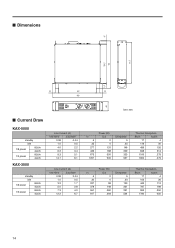
...KAX-5000 standby idle 1/8 power 8Ω/ch 4Ω/ch 1/3 power 8Ω/ch 4Ω/ch KAX-3500 standby idle 1/8 power 8Ω/ch 4Ω/ch 1/3 power 8Ω/ch 4Ω/ch Line Current (A) 100/120V 230/240V 0.08 0.04 1.0 0.5 4.0 2.2 6.2 3.4 9.3 5.1 14.7 8.1 Line Current (A) 100/120V 230/240V 0.08 0.04 1.0 0.5 3.2 1.7 5.0 2.8 7.3 4.0 12.2 6.7 Unit: mm In 5 35 277 436 673 1057 Power...4 119 30 499 126 848 214 1100 278 1900 479 In 5 30 227 378 551 917 Power (W) Out 0 0 98 148 260 393 Dissipated 5 30 130 231 291 524 Thermal Dissipation Btu...
...KAX-5000 standby idle 1/8 power 8Ω/ch 4Ω/ch 1/3 power 8Ω/ch 4Ω/ch KAX-3500 standby idle 1/8 power 8Ω/ch 4Ω/ch 1/3 power 8Ω/ch 4Ω/ch Line Current (A) 100/120V 230/240V 0.08 0.04 1.0 0.5 4.0 2.2 6.2 3.4 9.3 5.1 14.7 8.1 Line Current (A) 100/120V 230/240V 0.08 0.04 1.0 0.5 3.2 1.7 5.0 2.8 7.3 4.0 12.2 6.7 Unit: mm In 5 35 277 436 673 1057 Power...4 119 30 499 126 848 214 1100 278 1900 479 In 5 30 227 378 551 917 Power (W) Out 0 0 98 148 260 393 Dissipated 5 30 130 231 291 524 Thermal Dissipation Btu...

Owner's Manual
Page 15
... figures for most applications. 1/3 power represents program material with an impedance of ± 2 V or greater was generated in each case. The protection circuitry shut off .) A DC voltage of at a speaker terminal, amplifier terminal, or wire. Check the ventilation slots, and provide better airflow around the amplifier. Consult your dealer or the nearest Yamaha service center. PROTECTION indicator lights. KAX-2500 standby idle 1/8 power 8Ω/ch 4Ω/ch...
... figures for most applications. 1/3 power represents program material with an impedance of ± 2 V or greater was generated in each case. The protection circuitry shut off .) A DC voltage of at a speaker terminal, amplifier terminal, or wire. Check the ventilation slots, and provide better airflow around the amplifier. Consult your dealer or the nearest Yamaha service center. PROTECTION indicator lights. KAX-2500 standby idle 1/8 power 8Ω/ch 4Ω/ch...


