
Owner's Manual
Page 19
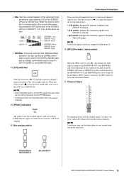
...to both [PAN] and [BAL] functions. In this switch on . The switch lights when on ( ) to send the respective channel's signal to the STEREO L/R bus or GROUP bus. When this switch is off , the PFL ...12 o'clock position, the sound of the stereo input channels (L/R) will be sent to the STE- NOTE To send the signal to each channel's signal is on ( ) to output the signal to the corresponding buses. •...switch When the [PFL] switch is sent. Use these controls to the AUX bus or GROUP bus. MG20XU/MG20 MG16XU/MG16 MG12XU/MG12 MG20XU/MG20/MG16XU/MG16/MG12XU/MG12 Owner's Manual 19
...to both [PAN] and [BAL] functions. In this switch on . The switch lights when on ( ) to send the respective channel's signal to the STEREO L/R bus or GROUP bus. When this switch is off , the PFL ...12 o'clock position, the sound of the stereo input channels (L/R) will be sent to the STE- NOTE To send the signal to each channel's signal is on ( ) to output the signal to the corresponding buses. •...switch When the [PFL] switch is sent. Use these controls to the AUX bus or GROUP bus. MG20XU/MG20 MG16XU/MG16 MG12XU/MG12 MG20XU/MG20/MG16XU/MG16/MG12XU/MG12 Owner's Manual 19
Owner's Manual
Page 31
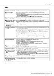
...each channel, channel faders, [STEREO] master fader, and [GROUP] fad- MG20XU/MG20/MG16XU/MG16/MG12XU/MG12 Owner's Manual 31 Use only one of cable to connect both jacks?... [PAN] set appropriately? No sound is output from the [SEND (AUX1 - 4)] jacks Are the [SEND MASTER] knobs and [AUX 1 - 4] for the channels you are dif- If, after switching ...61551; Are external instruments (including microphones) and speakers connected correctly? Are your Yamaha dealer. Cables with switches? If any specific problem should persist, please contact your cables ...
...each channel, channel faders, [STEREO] master fader, and [GROUP] fad- MG20XU/MG20/MG16XU/MG16/MG12XU/MG12 Owner's Manual 31 Use only one of cable to connect both jacks?... [PAN] set appropriately? No sound is output from the [SEND (AUX1 - 4)] jacks Are the [SEND MASTER] knobs and [AUX 1 - 4] for the channels you are dif- If, after switching ...61551; Are external instruments (including microphones) and speakers connected correctly? Are your Yamaha dealer. Cables with switches? If any specific problem should persist, please contact your cables ...
Owner's Manual
Page 32
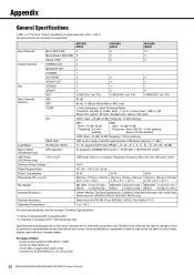
...E1, E2, E3 and E4 32 MG20XU/MG20/MG16XU/MG16/MG12XU/MG12 Owner's Manual Input channels Output channels Bus Input Channel Function Mono: MIC/LINE Mono/Stereo: MIC/LINE Stereo: LINE STEREO OUT MONITOR OUT PHONES AUX SEND GROUP OUT STEREO GROUP AUX PAD HPF COMP EQ PEAK LED Level Meter Pre... to + 40°C For other specifications, see the included "Technical Specifications." *1 Noise is measured with A-weighting filter. *2 Crosstalk is measured with your Yamaha dealer. FX) 4 (MG16XU: incl. Specifications and descriptions in this owner's manual are nominal if not specified...
...E1, E2, E3 and E4 32 MG20XU/MG20/MG16XU/MG16/MG12XU/MG12 Owner's Manual Input channels Output channels Bus Input Channel Function Mono: MIC/LINE Mono/Stereo: MIC/LINE Stereo: LINE STEREO OUT MONITOR OUT PHONES AUX SEND GROUP OUT STEREO GROUP AUX PAD HPF COMP EQ PEAK LED Level Meter Pre... to + 40°C For other specifications, see the included "Technical Specifications." *1 Noise is measured with A-weighting filter. *2 Crosstalk is measured with your Yamaha dealer. FX) 4 (MG16XU: incl. Specifications and descriptions in this owner's manual are nominal if not specified...

Owner's Manual
Page 34
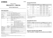
Male Female TRS Phone TS Phone White Red 34 MG20XU/MG20/MG16XU/MG16/MG12XU/MG12 Owner's Manual With properly designed receiving circuitry, cables with TS phone connectors. XLR type connectors are used for stereo headphone jacks, insert... in many cases. Appendix Jack and Connector List Jacks and Connectors Polarities MIC/LINE, MIC, STEREO OUT Pin 1: Ground Pin 2: Hot (+) Pin 3: Cold (-) MIC/LINE*, AUX SEND, GROUP OUT, MONITOR OUT, STEREO OUT PHONES Tip: Hot (+) Ring: Cold (-) Sleeve: Ground Tip: L Ring: R Sleeve: Ground Configurations INPUT OUTPUT XLR Jack Ring Sleeve Tip...
Male Female TRS Phone TS Phone White Red 34 MG20XU/MG20/MG16XU/MG16/MG12XU/MG12 Owner's Manual With properly designed receiving circuitry, cables with TS phone connectors. XLR type connectors are used for stereo headphone jacks, insert... in many cases. Appendix Jack and Connector List Jacks and Connectors Polarities MIC/LINE, MIC, STEREO OUT Pin 1: Ground Pin 2: Hot (+) Pin 3: Cold (-) MIC/LINE*, AUX SEND, GROUP OUT, MONITOR OUT, STEREO OUT PHONES Tip: Hot (+) Ring: Cold (-) Sleeve: Ground Tip: L Ring: R Sleeve: Ground Configurations INPUT OUTPUT XLR Jack Ring Sleeve Tip...

Owner's Manual
Page 36
...Numerics [1-2] switch 19, 23 [3-4] switch 19, 23 A [AC IN] jack 27 Attenuator Function 28 [AUX1] knob 23 [AUX1 - 3] knob 23 [AUX1 - 4] knob 18 [AUX (2, 4)/FX] knob 18 B [BAL] knob 18 Bus assign switch 19, 23 C [COMP] knob 17 D DI (direct box 29 D-PRE 8 E Effect program list 22 Equalizer...25 [ / ] POWER switch 27 [PRE] switch 18 [PROGRAM] knob 22 R Rack mount brackets 35 RCA Pin 34 Reverb and Delay Time 11 S [SEND] jack 24 [SEND MASTER] section 26 Shelving 18 [SOURCE]/[SOURCE SELECT 25 [ST] switch 19, 23, 26 Stereo input jack 16 [STEREO] master fader 27 [STEREO] section...
...Numerics [1-2] switch 19, 23 [3-4] switch 19, 23 A [AC IN] jack 27 Attenuator Function 28 [AUX1] knob 23 [AUX1 - 3] knob 23 [AUX1 - 4] knob 18 [AUX (2, 4)/FX] knob 18 B [BAL] knob 18 Bus assign switch 19, 23 C [COMP] knob 17 D DI (direct box 29 D-PRE 8 E Effect program list 22 Equalizer...25 [ / ] POWER switch 27 [PRE] switch 18 [PROGRAM] knob 22 R Rack mount brackets 35 RCA Pin 34 Reverb and Delay Time 11 S [SEND] jack 24 [SEND MASTER] section 26 Shelving 18 [SOURCE]/[SOURCE SELECT 25 [ST] switch 19, 23, 26 Stereo input jack 16 [STEREO] master fader 27 [STEREO] section...
Technical Specifications
Page 1
...Analog Output Characteristics 0 dBu = 0.775 Vrms Output Terminals Actual Source Impedance For Use With Nominal STEREO OUT [L, R] 75 Ω MONITOR OUT [L, R] GROUP OUT [1 - 4] AUX SEND [1 - 4] PHONES 150 Ω 110 Ω *3 1 = GND, 2 = HOT, 3 = COLD *5 Tip = HOT, Ring = COLD, Sleeve = GND 600 ...2, Stereo [LINE]: 2 STEREO OUT: 2, PHONES: 1, MONITOR OUT: 1, AUX SEND: 4, GROUP OUT: 4 STEREO: 1, GROUP: 4, AUX: 4 (MG16XU: incl. Since specifications, equipment or options may not be the same in every locale, please check with your Yamaha dealer. CH 8 26 dB CH 1 - CH 15/16 HIGH: Gain...
...Analog Output Characteristics 0 dBu = 0.775 Vrms Output Terminals Actual Source Impedance For Use With Nominal STEREO OUT [L, R] 75 Ω MONITOR OUT [L, R] GROUP OUT [1 - 4] AUX SEND [1 - 4] PHONES 150 Ω 110 Ω *3 1 = GND, 2 = HOT, 3 = COLD *5 Tip = HOT, Ring = COLD, Sleeve = GND 600 ...2, Stereo [LINE]: 2 STEREO OUT: 2, PHONES: 1, MONITOR OUT: 1, AUX SEND: 4, GROUP OUT: 4 STEREO: 1, GROUP: 4, AUX: 4 (MG16XU: incl. Since specifications, equipment or options may not be the same in every locale, please check with your Yamaha dealer. CH 8 26 dB CH 1 - CH 15/16 HIGH: Gain...

