

Owner's Manual
Page 2
... FOR THE UNITED KINGDOM Connecting the Plug and Cord WARNING: THIS APPARATUS MUST BE EARTHED IMPORTANT. When a cart is necessary either to products distributed by Yamaha-Kemble Music (U.K.) Ltd. (3 wires) receptacles, and the point where they exit from the apparatus. 11 Only use caution when moving the cart/ apparatus combination to...
... FOR THE UNITED KINGDOM Connecting the Plug and Cord WARNING: THIS APPARATUS MUST BE EARTHED IMPORTANT. When a cart is necessary either to products distributed by Yamaha-Kemble Music (U.K.) Ltd. (3 wires) receptacles, and the point where they exit from the apparatus. 11 Only use caution when moving the cart/ apparatus combination to...

Owner's Manual
Page 3
Precautions - Failure to prevent the internal temperature rising too high. You could receive an electrical shock. CAUTION Installation ● Keep this unit be dropped or the cabinet be : 5 cm at the front and rear to do so is a fire and electrical shock hazard. ● Should this unit away from the AC outlet. Locations subject to excessive humidity or dust accumulation. ● Do not place the power cord close to amplifier outputs. A damaged power cord is a potential fire and electrical shock hazard. ● Do not touch the power plug with a ...
Precautions - Failure to prevent the internal temperature rising too high. You could receive an electrical shock. CAUTION Installation ● Keep this unit be dropped or the cabinet be : 5 cm at the front and rear to do so is a fire and electrical shock hazard. ● Should this unit away from the AC outlet. Locations subject to excessive humidity or dust accumulation. ● Do not place the power cord close to amplifier outputs. A damaged power cord is a potential fire and electrical shock hazard. ● Do not touch the power plug with a ...

Owner's Manual
Page 4
... only to accessories and/or another product use the product. 2. Failure to follow instructions could void your authority, granted by YAMAHA CORPORATION OF AMERICA. 4 Modifications not expressly approved by Yamaha may not match the actual appearance of their respective owners. FCC INFORMATION (U.S.A.) 1. Pin 3: cold (-). Connector pin assignments ● XLR-type...
... only to accessories and/or another product use the product. 2. Failure to follow instructions could void your authority, granted by YAMAHA CORPORATION OF AMERICA. 4 Modifications not expressly approved by Yamaha may not match the actual appearance of their respective owners. FCC INFORMATION (U.S.A.) 1. Pin 3: cold (-). Connector pin assignments ● XLR-type...

Owner's Manual
Page 5
... is running hot. • Variable-speed low-noise fans ensure high reliability. This Owner's Manual covers the four models: P7000S, P5000S, P3500S and P2500S power amplifiers. Introduction Thank you for years to come. Features • With two types of input jacks (balanced XLR and balanced phone) ...and three types of the YAMAHA P7000S, P5000S, P3500S or P2500S power amplifier. Please read through twin amplifier systems), and BRIDGE (where the unit operates as a single high-...
... is running hot. • Variable-speed low-noise fans ensure high reliability. This Owner's Manual covers the four models: P7000S, P5000S, P3500S and P2500S power amplifiers. Introduction Thank you for years to come. Features • With two types of input jacks (balanced XLR and balanced phone) ...and three types of the YAMAHA P7000S, P5000S, P3500S or P2500S power amplifier. Please read through twin amplifier systems), and BRIDGE (where the unit operates as a single high-...

Owner's Manual
Page 6
Controls and Functions ■ Front Panel 2 4 8 13 576 8 1 POWER switch and indicator Press to toggle the power on the rear panel is set ON. (See page 7.) 8 Air intakes The amplifier uses forced-air cooling. Specifically, lights up if the heat sink overheats, or if a DC voltage is lit up green when the corresponding channel's output level exceeds 2 Vrms (equivalent to the position of the corresponding channel, in effect. How to install the security cover (1) Use the supplied hex wrench to lock in from the speakers while this indicator is detected at initial...
Controls and Functions ■ Front Panel 2 4 8 13 576 8 1 POWER switch and indicator Press to toggle the power on the rear panel is set ON. (See page 7.) 8 Air intakes The amplifier uses forced-air cooling. Specifically, lights up if the heat sink overheats, or if a DC voltage is lit up green when the corresponding channel's output level exceeds 2 Vrms (equivalent to the position of the corresponding channel, in effect. How to install the security cover (1) Use the supplied hex wrench to lock in from the speakers while this indicator is detected at initial...

Owner's Manual
Page 7
... ON, the amplifier adds low-frequency compensation so as shown below. NOTE: This feature provides improved frequency reponse on speakers such as the YAMAHA S112 and S115. 3 INPUT jacks (Channels A, B) Two jack types are provided for each channel) Use these controls to select the filter type and adjust...
... ON, the amplifier adds low-frequency compensation so as shown below. NOTE: This feature provides improved frequency reponse on speakers such as the YAMAHA S112 and S115. 3 INPUT jacks (Channels A, B) Two jack types are provided for each channel) Use these controls to select the filter type and adjust...

Owner's Manual
Page 8
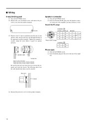
4 STEREO/PARALLEL/BRIDGE switch Use this terminal to connect to ground or to connect to the Channel B output jacks. • PARALLEL mode The Channel A input signal is output from the BRIDGE output jacks. The Channel A input goes to the Channel A output jacks, and the Channel B input goes to the chassis of the mixer, preamp, or other device in your system. 8 If you must use this switch to select the operating mode. • STEREO mode Channels A and B operate independently (as with hum or noise, use the Channel A volume control knob. 5 SPEAKER jacks Neutrik NL4FC Speakon output ...
4 STEREO/PARALLEL/BRIDGE switch Use this terminal to connect to ground or to connect to the Channel B output jacks. • PARALLEL mode The Channel A input signal is output from the BRIDGE output jacks. The Channel A input goes to the Channel A output jacks, and the Channel B input goes to the chassis of the mixer, preamp, or other device in your system. 8 If you must use this switch to select the operating mode. • STEREO mode Channels A and B operate independently (as with hum or noise, use the Channel A volume control knob. 5 SPEAKER jacks Neutrik NL4FC Speakon output ...

Owner's Manual
Page 9
Connection configurations for STEREO and PARALLEL modes When using 5-way binding post output jacks Connection configurations for BRIDGE mode When using 5-way binding post output jacks STEREO BRIDGE PARALLEL or STEREO BRIDGE PARALLEL - 1+ +1- (-) (+) BRIDGE STEREO BRIDGE PARALLEL - 1+ +1- (-) (+) BRIDGE Minimum speaker impedance: 4 Ω When using Speakon connector LOCK LOCK SPEAKERS 3 2 23 + 1+ - 1- 1+ + 1- - 2+ + 2- - Minimum speaker impedance: 8 Ω Minimum speaker impedance: 4 Ω 9 Note that your speakers' impedance is not less than the ...
Connection configurations for STEREO and PARALLEL modes When using 5-way binding post output jacks Connection configurations for BRIDGE mode When using 5-way binding post output jacks STEREO BRIDGE PARALLEL or STEREO BRIDGE PARALLEL - 1+ +1- (-) (+) BRIDGE STEREO BRIDGE PARALLEL - 1+ +1- (-) (+) BRIDGE Minimum speaker impedance: 4 Ω When using Speakon connector LOCK LOCK SPEAKERS 3 2 23 + 1+ - 1- 1+ + 1- - 2+ + 2- - Minimum speaker impedance: 8 Ω Minimum speaker impedance: 4 Ω 9 Note that your speakers' impedance is not less than the ...
Owner's Manual
Page 10
... each speaker cable, and pass the bare wire through the holes in the USA: Please use Class 3 wiring. (P7000S, P5000S) Please use Class 2 wiring. (P3500S, P2500S) Be sure that the bare wire ends do not jut out from the terminals and touch the chassis. Neutrik NL4FC plugs CHANNEL A STEREO or PARALLEL...
... each speaker cable, and pass the bare wire through the holes in the USA: Please use Class 3 wiring. (P7000S, P5000S) Please use Class 2 wiring. (P3500S, P2500S) Be sure that the bare wire ends do not jut out from the terminals and touch the chassis. Neutrik NL4FC plugs CHANNEL A STEREO or PARALLEL...

Owner's Manual
Page 11
Ventilation panel(s) Use 1U-size blank panel(s). 480 44 Unit: mm If mounting up to four amplifiers in an open -backed rack, and when mounting any number of amplifiers in a close-backed rack Install ventilation panels above and below each amplifer. Note: EIA stands for Electronic Industries Alliance. Ventilation panel (Attach to the front or rear of the rack.) When mounting five or more amplifiers in an open -backed rack Install a ventilation panel as shown below. Also be sure to install ventilation panel(s) as shown below . 11 Rack Mounting Mounting in a...
Ventilation panel(s) Use 1U-size blank panel(s). 480 44 Unit: mm If mounting up to four amplifiers in an open -backed rack, and when mounting any number of amplifiers in a close-backed rack Install ventilation panels above and below each amplifer. Note: EIA stands for Electronic Industries Alliance. Ventilation panel (Attach to the front or rear of the rack.) When mounting five or more amplifiers in an open -backed rack Install a ventilation panel as shown below. Also be sure to install ventilation panel(s) as shown below . 11 Rack Mounting Mounting in a...

Owner's Manual
Page 12
...215; 456 mm Weight 12 kg 12 kg 15 kg 14 kg Included Accessories Security cover (with your Yamaha dealer. Inrush Current: 25A (P7000S, P5000S)/66A (P3500S)/68A (P2500S) Conforms to Environments: E1, E2, E3 and E4 12 protection Temp. min. 20 Hz - 20 ...750 W × 2 1100 W × 2 2200 W × 1 P5000S 525 W × 2 750 W × 2 1500 W × 1 P3500S 390 W × 2 590 W × 2 1180 W × 1 P2500S 275 W × 2 390 W × 2 780 W × 1 20 Hz - 20 kHz THD + N = 0.1% 8 Ω/STEREO 4 Ω/STEREO 8 Ω/BRIDGE 700 W × 2 650 W × 2 (...
...215; 456 mm Weight 12 kg 12 kg 15 kg 14 kg Included Accessories Security cover (with your Yamaha dealer. Inrush Current: 25A (P7000S, P5000S)/66A (P3500S)/68A (P2500S) Conforms to Environments: E1, E2, E3 and E4 12 protection Temp. min. 20 Hz - 20 ...750 W × 2 1100 W × 2 2200 W × 1 P5000S 525 W × 2 750 W × 2 1500 W × 1 P3500S 390 W × 2 590 W × 2 1180 W × 1 P2500S 275 W × 2 390 W × 2 780 W × 1 20 Hz - 20 kHz THD + N = 0.1% 8 Ω/STEREO 4 Ω/STEREO 8 Ω/BRIDGE 700 W × 2 650 W × 2 (...

Owner's Manual
Page 14
■ Dimensions ■ Current Draw P7000S standby idle 1/8 power 8Ω/ch 4Ω/ch 1/3 power 8Ω/ch 4Ω/ch P5000S standby idle 1/8 power 8Ω/ch 4Ω/ch 1/3 power 8Ω/ch 4Ω/ch P3500S standby idle 1/8 power 8Ω/ch 4Ω/ch 1/3 power 8Ω/ch 4Ω/ch Line Current (A) 100/120V 230/240V 0.08 0.04 1.0 0.5 5.4 3.0 8.5 4.7 12.8 7.0 20.6 11.3 Line Current (A) 100/120V 230/240V 0.08 0.04 1.0 0.5 4.0 2.2 6.2 3.4 9.3 5.1 14.7 8.1 Line Current (A) 100/120V 230/240V 0.08 0.04 1.0 0.5 3.2 1.7...
■ Dimensions ■ Current Draw P7000S standby idle 1/8 power 8Ω/ch 4Ω/ch 1/3 power 8Ω/ch 4Ω/ch P5000S standby idle 1/8 power 8Ω/ch 4Ω/ch 1/3 power 8Ω/ch 4Ω/ch P3500S standby idle 1/8 power 8Ω/ch 4Ω/ch 1/3 power 8Ω/ch 4Ω/ch Line Current (A) 100/120V 230/240V 0.08 0.04 1.0 0.5 5.4 3.0 8.5 4.7 12.8 7.0 20.6 11.3 Line Current (A) 100/120V 230/240V 0.08 0.04 1.0 0.5 4.0 2.2 6.2 3.4 9.3 5.1 14.7 8.1 Line Current (A) 100/120V 230/240V 0.08 0.04 1.0 0.5 3.2 1.7...

Owner's Manual
Page 15
... been shut down. (All indicators are off the power to these figures for most applications. 1/3 power represents program material with occasional clipping. P2500S standby idle 1/8 power 8Ω/ch 4Ω/ch 1/3 power 8Ω/ch 4Ω/ch Line Current (A) 100/120V 230/240V 0.08 0.04 1.0...8486; (STEREO/PARALLEL mode) or 8 Ω (BRIDGE mode). P3500S, P2500S Indicator(s) PROTECTION indicator lights. The relay operates to protect the power transistors. Consult your dealer or the nearest Yamaha service center. TEMP indicator lights. Locate and correct the cause of ±...
... been shut down. (All indicators are off the power to these figures for most applications. 1/3 power represents program material with occasional clipping. P2500S standby idle 1/8 power 8Ω/ch 4Ω/ch 1/3 power 8Ω/ch 4Ω/ch Line Current (A) 100/120V 230/240V 0.08 0.04 1.0...8486; (STEREO/PARALLEL mode) or 8 Ω (BRIDGE mode). P3500S, P2500S Indicator(s) PROTECTION indicator lights. The relay operates to protect the power transistors. Consult your dealer or the nearest Yamaha service center. TEMP indicator lights. Locate and correct the cause of ±...
Owner's Manual
Page 16
... Kuznetskii Most street, Moscow, 107996, Russia Tel: 495 626 0660 OTHER EUROPEAN COUNTRIES Yamaha Music Europe GmbH Siemensstraße 22-34, 25462 Rellingen, Germany Tel: +49-4101-3030 AFRICA Yamaha Corporation, Asia-Pacific Music Marketing Group Nakazawa-cho 10-1, Naka-ku, Hamamatsu,...430-8650 Tel: +81-53-460-2441 Yamaha Pro Audio global web site http://www.yamahaproaudio.com/ Yamaha Manual Library http://www.yamaha.co.jp/manual/ U.R.G., Pro Audio & Digital Musical Instrument Division, Yamaha Corporation © 2003 Yamaha Corporation WB09700 001CRZCx.x-xxE0 Printed in den jeweiligen ...
... Kuznetskii Most street, Moscow, 107996, Russia Tel: 495 626 0660 OTHER EUROPEAN COUNTRIES Yamaha Music Europe GmbH Siemensstraße 22-34, 25462 Rellingen, Germany Tel: +49-4101-3030 AFRICA Yamaha Corporation, Asia-Pacific Music Marketing Group Nakazawa-cho 10-1, Naka-ku, Hamamatsu,...430-8650 Tel: +81-53-460-2441 Yamaha Pro Audio global web site http://www.yamahaproaudio.com/ Yamaha Manual Library http://www.yamaha.co.jp/manual/ U.R.G., Pro Audio & Digital Musical Instrument Division, Yamaha Corporation © 2003 Yamaha Corporation WB09700 001CRZCx.x-xxE0 Printed in den jeweiligen ...
