
Owner's Manual
Page 2
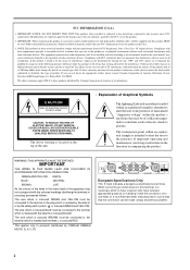
...-in is being affected by YAMAHA KEMBLE MUSIC (U.K.) LTD. If you can not locate the appropriate retailer, please contact Yamaha Corporation of important operating and maintenance (servicing) instructions in this type of radio or TV interference, relocate/reorient the antenna. The wire which is coloured BLUE must be connected to the terminal in the USA. 3. European Specifications Only This mark indicates...
...-in is being affected by YAMAHA KEMBLE MUSIC (U.K.) LTD. If you can not locate the appropriate retailer, please contact Yamaha Corporation of important operating and maintenance (servicing) instructions in this type of radio or TV interference, relocate/reorient the antenna. The wire which is coloured BLUE must be connected to the terminal in the USA. 3. European Specifications Only This mark indicates...
Owner's Manual
Page 3
..., and unplug the power cable plug from the AC outlet. Doing so may be damaged, turn the power switch off, remove the power plug from the AC outlet, and contact your dealer for this unit. Using the unit with liquid or small metal objects on top of the power cord. If you continue using the unit without heeding this instruction, fire or electrical...
..., and unplug the power cable plug from the AC outlet. Doing so may be damaged, turn the power switch off, remove the power plug from the AC outlet, and contact your dealer for this unit. Using the unit with liquid or small metal objects on top of the power cord. If you continue using the unit without heeding this instruction, fire or electrical...
Owner's Manual
Page 4
... 1: ground, pin 2: hot (+), and pin 3: cold (-). - Operation • Use only speaker cables when connecting speakers to excessive humidity or dust accumulation. • Hold the power cord plug when disconnecting it from the AC outlet, and remove all the windows closed, or places that receive direct sunlight. - FOR CORRECT OPERATION - Locations subject to amplifier outputs. Never pull the cord. Doing so is a fire hazard. • Do...
... 1: ground, pin 2: hot (+), and pin 3: cold (-). - Operation • Use only speaker cables when connecting speakers to excessive humidity or dust accumulation. • Hold the power cord plug when disconnecting it from the AC outlet, and remove all the windows closed, or places that receive direct sunlight. - FOR CORRECT OPERATION - Locations subject to amplifier outputs. Never pull the cord. Doing so is a fire hazard. • Do...
Owner's Manual
Page 5
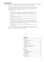
... audio performance. In order to the PC9500N and PC4800N power amplifier. Contents Introduction 5 Controls and Functions 6 Front Panel 6 Rear Panel 7 Speaker connections 8 Connection 9 Using a Euroblock connector 9 Speaker Connection 9 Air Flow 10 Rack Mounting 10 Specifications 11 General Specifications 11 Block Diagram 12 Dimensions 13 Troubleshooting 14 Performance graph 14 5 This Owner's Manual applies to take full advantage of your power amplifier and enjoy long and trouble-free operation, please read this Owner's Manual carefully before using your Power Amplifier...
... audio performance. In order to the PC9500N and PC4800N power amplifier. Contents Introduction 5 Controls and Functions 6 Front Panel 6 Rear Panel 7 Speaker connections 8 Connection 9 Using a Euroblock connector 9 Speaker Connection 9 Air Flow 10 Rack Mounting 10 Specifications 11 General Specifications 11 Block Diagram 12 Dimensions 13 Troubleshooting 14 Performance graph 14 5 This Owner's Manual applies to take full advantage of your power amplifier and enjoy long and trouble-free operation, please read this Owner's Manual carefully before using your Power Amplifier...
Owner's Manual
Page 6
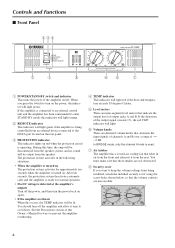
...: • When the amplifier is turned on The protection system activates for normal operation. • If a DC voltage is detected at the amplifier's outputs Turn off the power, and then turn off . In BRIDGE mode, only the channel A knob is used. 7 Air intakes The amplifier has a forced-air cooling fan that attenuate the input signals of channels A and B over a range of the output signal exceeds 1%, the red CLIP indicator will...
...: • When the amplifier is turned on The protection system activates for normal operation. • If a DC voltage is detected at the amplifier's outputs Turn off the power, and then turn off . In BRIDGE mode, only the channel A knob is used. 7 Air intakes The amplifier has a forced-air cooling fan that attenuate the input signals of channels A and B over a range of the output signal exceeds 1%, the red CLIP indicator will...
Owner's Manual
Page 7
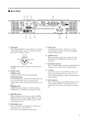
... post output jacks. 7 ■ Rear Panel 12 3 4 5 67 8 9 1 XLR inputs These balanced XLR-3-31 type connectors are wired pin 1-ground, pin 2-hot (+), and pin 3-cold (-). They are used to the DATA port 5, this inlet. 9 GND terminals This is connected to turn on and off the HPF (High Pass Filter) for each channel. Speakon type cable plugs can be connected here to monitor or control the amplifier from...
... post output jacks. 7 ■ Rear Panel 12 3 4 5 67 8 9 1 XLR inputs These balanced XLR-3-31 type connectors are wired pin 1-ground, pin 2-hot (+), and pin 3-cold (-). They are used to the DATA port 5, this inlet. 9 GND terminals This is connected to turn on and off the HPF (High Pass Filter) for each channel. Speakon type cable plugs can be connected here to monitor or control the amplifier from...
Owner's Manual
Page 8
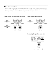
Refer to this amplifier in BRIDGE mode or -+ +- -+ Speaker min. 4Ω Speaker min. 4Ω Speaker min. 8Ω When using the Speakon connector Speaker min. 8Ω * Use the 1+(+) and 2+(-) pins of the 2 jack. 8 The speaker impedance will depend on the connection method and on the number of connection. Connections in STEREO/PARALLEL modes Connections in the following diagrams, and make sure that the speaker impedance is not less than the value prescribed for...
Refer to this amplifier in BRIDGE mode or -+ +- -+ Speaker min. 4Ω Speaker min. 4Ω Speaker min. 8Ω When using the Speakon connector Speaker min. 8Ω * Use the 1+(+) and 2+(-) pins of the 2 jack. 8 The speaker impedance will depend on the connection method and on the number of connection. Connections in STEREO/PARALLEL modes Connections in the following diagrams, and make sure that the speaker impedance is not less than the value prescribed for...
Owner's Manual
Page 9
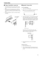
... Use a screwdriver to page 8 for speaker polarity. 15mm* -G + * Shown actual size. Speakon type jack 1. Turn off the POWER switch. 2. Refer to fix the wires. 3. Turn off the POWER switch. 2. Reattach the protective cover over the speaker terminals. Attach the Euroblock connector to open the ports. 2. Insert the wires into the Speakon type jacks on the rear of this time make sure that they touch the chassis. Connection ■ Using...
... Use a screwdriver to page 8 for speaker polarity. 15mm* -G + * Shown actual size. Speakon type jack 1. Turn off the POWER switch. 2. Refer to fix the wires. 3. Turn off the POWER switch. 2. Reattach the protective cover over the speaker terminals. Attach the Euroblock connector to open the ports. 2. Insert the wires into the Speakon type jacks on the rear of this time make sure that they touch the chassis. Connection ■ Using...
Owner's Manual
Page 10
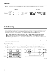
... diagram of a panel on the top slot or the top panel of the rack. Air intake Front Side View Air exhaust Rear View Rack Mounting If multiple high-power amp units are mounted in through the front opening and goes out the rear. Rack: Leave a gap of 10 cm or more maximum static pressure. Fan kit PC9500N/ PC4800N PC9500N...
... diagram of a panel on the top slot or the top panel of the rack. Air intake Front Side View Air exhaust Rear View Rack Mounting If multiple high-power amp units are mounted in through the front opening and goes out the rear. Rack: Leave a gap of 10 cm or more maximum static pressure. Fan kit PC9500N/ PC4800N PC9500N...
Owner's Manual
Page 11
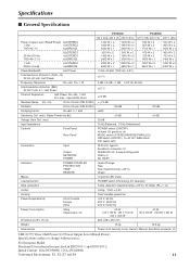
... Accessories Power cord, Security cover, Owner's Manual, Euroblock connector (2) 0 dB=0.775 Vrms, Half Power=1/2 Power Output Level (Rated Power) Specifications subject to change without notice. For European Model Purchaser/User information specified in EN55103-1 and EN55103-2. max., input 600Ω shunt ≥70 dB Residual Noise Vol. Specifications ■ General Specifications PC9500N PC4800N 120 V (US)/ 240 V (A) 230 V (EU) 120 V (US)/ 240 V (A) 230 V (EU) Power Output Level (Rated Power) 8Ω/STEREO 1 kHz 4Ω/STEREO...
... Accessories Power cord, Security cover, Owner's Manual, Euroblock connector (2) 0 dB=0.775 Vrms, Half Power=1/2 Power Output Level (Rated Power) Specifications subject to change without notice. For European Model Purchaser/User information specified in EN55103-1 and EN55103-2. max., input 600Ω shunt ≥70 dB Residual Noise Vol. Specifications ■ General Specifications PC9500N PC4800N 120 V (US)/ 240 V (A) 230 V (EU) 120 V (US)/ 240 V (A) 230 V (EU) Power Output Level (Rated Power) 8Ω/STEREO 1 kHz 4Ω/STEREO...
Owner's Manual
Page 14
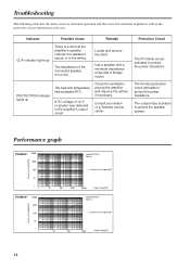
... a Yamaha service center. The impedance of 4Ω (8Ω in each case. Use a speaker with a minimum impedance of the connected speaker is a short at the amplifier's speaker outputs, the speaker's inputs, or in the wiring. Locate and remove the short. The thermal protection circuit activates to protect the power transistors. The output relay activates to protect the speaker system. Performance graph PC9500N 10000 1000 100 10 1 1 PC4800N 10000 1000 100 10 1 1 Power consumption[W] Power consumption[W] Mode:STEREO...
... a Yamaha service center. The impedance of 4Ω (8Ω in each case. Use a speaker with a minimum impedance of the connected speaker is a short at the amplifier's speaker outputs, the speaker's inputs, or in the wiring. Locate and remove the short. The thermal protection circuit activates to protect the power transistors. The output relay activates to protect the speaker system. Performance graph PC9500N 10000 1000 100 10 1 1 PC4800N 10000 1000 100 10 1 1 Power consumption[W] Power consumption[W] Mode:STEREO...


