
Owner's Manual
Page 4
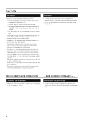
... unit will heat up inside a car with wet hands. If the airflow is a fire hazard. • Do not use this amplifier for normal ventilation. FOR CORRECT OPERATION - Locations exposed to amplifier outputs. Doing so is a potential fire and electrical shock hazard. • Do not touch the power plug with all connecting cables...
... unit will heat up inside a car with wet hands. If the airflow is a fire hazard. • Do not use this amplifier for normal ventilation. FOR CORRECT OPERATION - Locations exposed to amplifier outputs. Doing so is a potential fire and electrical shock hazard. • Do not touch the power plug with all connecting cables...
Owner's Manual
Page 5
...heat sink overheating, and a REMOTE indicator that cuts frequencies below 40 Hz, and detented attenuators and level meters for purchasing a Yamaha PC9500N, or PC4800N Series Power Amplifier. Contents Introduction 5 Controls and Functions 6 Front Panel 6 Rear Panel 7 Speaker connections 8 Connection 9 Using a Euroblock connector ... long and trouble-free operation, please read this Owner's Manual carefully before using your Power Amplifier. The PC Series of power amplifiers was developed from Yamaha's wealth of experience in which the two internal amps function as a single mono amp. ...
...heat sink overheating, and a REMOTE indicator that cuts frequencies below 40 Hz, and detented attenuators and level meters for purchasing a Yamaha PC9500N, or PC4800N Series Power Amplifier. Contents Introduction 5 Controls and Functions 6 Front Panel 6 Rear Panel 7 Speaker connections 8 Connection 9 Using a Euroblock connector ... long and trouble-free operation, please read this Owner's Manual carefully before using your Power Amplifier. The PC Series of power amplifiers was developed from Yamaha's wealth of experience in which the two internal amps function as a single mono amp. ...
Owner's Manual
Page 6
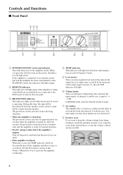
...this Owner's Manual for ways to enter STAND-BY mode, this indicator will light orange. 2 REMOTE indicator This indicator will light green if the amplifier is being controlled from being modified, attach the included security cover using the screw holes shown below, so that indicate the output level of output... not obstructed. 8 Security cover If you press the switch to cool down. In BRIDGE mode, only the channel A knob is detected at the amplifier's outputs Turn off the power, and then turn off . The protection system activates in air from the front and exhausts it time to turn on...
...this Owner's Manual for ways to enter STAND-BY mode, this indicator will light orange. 2 REMOTE indicator This indicator will light green if the amplifier is being controlled from being modified, attach the included security cover using the screw holes shown below, so that indicate the output level of output... not obstructed. 8 Security cover If you press the switch to cool down. In BRIDGE mode, only the channel A knob is detected at the amplifier's outputs Turn off the power, and then turn off . The protection system activates in air from the front and exhausts it time to turn on...
Owner's Manual
Page 7
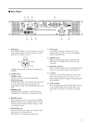
... operate simultaneously, functioning as a single mono amp. 5 DATA ports An external control unit or interface box can be connected here to monitor or control the amplifier from the external device. 6 AMP ID switch When an external control unit is connected to the DATA port 5, this DIP switch is active. 2 MODE switch...
... operate simultaneously, functioning as a single mono amp. 5 DATA ports An external control unit or interface box can be connected here to monitor or control the amplifier from the external device. 6 AMP ID switch When an external control unit is connected to the DATA port 5, this DIP switch is active. 2 MODE switch...
Owner's Manual
Page 8
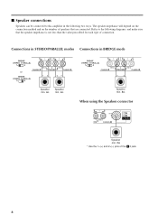
■ Speaker connections Speakers can be connected to the following two ways. Refer to this amplifier in BRIDGE mode or -+ +- -+ Speaker min. 4Ω Speaker min. 4Ω Speaker min. 8Ω When using the Speakon connector Speaker min. 8Ω * Use the 1+(+) and 2+(-) pins ...
■ Speaker connections Speakers can be connected to the following two ways. Refer to this amplifier in BRIDGE mode or -+ +- -+ Speaker min. 4Ω Speaker min. 4Ω Speaker min. 8Ω When using the Speakon connector Speaker min. 8Ω * Use the 1+(+) and 2+(-) pins ...
Owner's Manual
Page 9
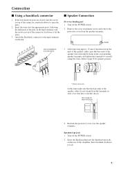
... bare ends of the speaker wires through the holes in the corresponding speaker terminals and tighten the terminals to securely clamp the wires. At this amplifier, then turn the screws on the rear of the connector counterclockwise to lock. 9 Speakon type jack 1.
... bare ends of the speaker wires through the holes in the corresponding speaker terminals and tighten the terminals to securely clamp the wires. At this amplifier, then turn the screws on the rear of the connector counterclockwise to lock. 9 Speakon type jack 1.
Owner's Manual
Page 10
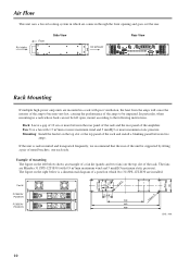
... a gap of 10 cm or more maximum static pressure. Mounting: Install the fan kit on the left open, mount according to be impaired. Fan kit PC9500N/ PC4800N PC9500N/ PC4800N 71.5±0.1 78 76.2 88 4-C15 78 4-ø4.5 71.5±0.1 248 463 480 4-6.5 x 11 Unit : mm 10 Fan: Use a fan with 1.5 m3...slot or the top panel of the rack and install a blanking panel between the rear panel of the rack and the rear panel of the amplifier. Air intake Front Side View Air exhaust Rear View Rack Mounting If multiple high-power amp units are installed. If the unit is rack mounted...
... a gap of 10 cm or more maximum static pressure. Mounting: Install the fan kit on the left open, mount according to be impaired. Fan kit PC9500N/ PC4800N PC9500N/ PC4800N 71.5±0.1 78 76.2 88 4-C15 78 4-ø4.5 71.5±0.1 248 463 480 4-6.5 x 11 Unit : mm 10 Fan: Use a fan with 1.5 m3...slot or the top panel of the rack and install a blanking panel between the rear panel of the rack and the rear panel of the amplifier. Air intake Front Side View Air exhaust Rear View Rack Mounting If multiple high-power amp units are installed. If the unit is rack mounted...
Owner's Manual
Page 14
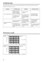
... output relay activates to protect the power transistors. Consult your dealer or a Yamaha service center. Protection Circuit The PC limiter circuit activates to protect the speaker system. Check the ventilation around the amplifier and improve the airflow if necessary. Performance graph PC9500N 10000 1000 100 10 1 1 PC4800N 10000 1000 100 10 1 1 Power consumption... 90°C. PROTECTION indicator lights up There is too low. Locate and remove the short. A DC voltage of the connected speaker is a short at the amplifier's speaker outputs, the speaker's inputs, or in the...
... output relay activates to protect the power transistors. Consult your dealer or a Yamaha service center. Protection Circuit The PC limiter circuit activates to protect the speaker system. Check the ventilation around the amplifier and improve the airflow if necessary. Performance graph PC9500N 10000 1000 100 10 1 1 PC4800N 10000 1000 100 10 1 1 Power consumption... 90°C. PROTECTION indicator lights up There is too low. Locate and remove the short. A DC voltage of the connected speaker is a short at the amplifier's speaker outputs, the speaker's inputs, or in the...

