
Owner's Manual
Page 2
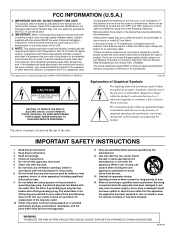
... instructions. 2 Keep these requirements provides a reasonable level of the obsolete outlet. 10 Protect the power cord from the apparatus. 11 Only use only high quality shielded cables. A grounding type plug has two blades and a third grounding prong. If the antenna lead-in is used . When a cart is 300 ohm ribbon lead, change the lead-in the USA. 3. NOTE: This product has been tested...
... instructions. 2 Keep these requirements provides a reasonable level of the obsolete outlet. 10 Protect the power cord from the apparatus. 11 Only use only high quality shielded cables. A grounding type plug has two blades and a third grounding prong. If the antenna lead-in is used . When a cart is 300 ohm ribbon lead, change the lead-in the USA. 3. NOTE: This product has been tested...
Owner's Manual
Page 3
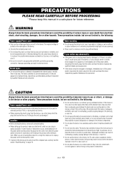
... , immediately turn off the power switch, disconnect the electric plug from the outlet, and have the device inspected by qualified Yamaha service personnel. • If this device is adequate space between the device and surrounding walls or other devices: at least 10cm at the minimum level. These precautions include, but are not limited to be used in...
... , immediately turn off the power switch, disconnect the electric plug from the outlet, and have the device inspected by qualified Yamaha service personnel. • If this device is adequate space between the device and surrounding walls or other devices: at least 10cm at the minimum level. These precautions include, but are not limited to be used in...
Owner's Manual
Page 4
... your audio system, always turn the power off when the device is not grounded, be sure to connect the ground screw to a confirmed ground point before plugging the device into any gaps or openings on the rear panel of this happens, turn off the power for all volume levels to minimum. • Use only speaker cables for connecting Speakon connectors. Yamaha cannot be turned off...
... your audio system, always turn the power off when the device is not grounded, be sure to connect the ground screw to a confirmed ground point before plugging the device into any gaps or openings on the rear panel of this happens, turn off the power for all volume levels to minimum. • Use only speaker cables for connecting Speakon connectors. Yamaha cannot be turned off...
Owner's Manual
Page 5
... 5 Controls and Functions 6 Front Panel 6 Rear Panel 7 Speaker connections 8 Connection 9 Using a Euroblock connector 9 Speaker Connection 9 Air Flow 10 Rack Mounting 10 Specifications 11 General Specifications 11 Block Diagram 12 Dimensions 13 Troubleshooting 14 Current Draw 14 5 For the latest information about amp control devices, please visit our website: http://www.yamahaproaudio.com/ This Owner's Manual applies to take full advantage of your power amplifier and enjoy long and trouble-free operation...
... 5 Controls and Functions 6 Front Panel 6 Rear Panel 7 Speaker connections 8 Connection 9 Using a Euroblock connector 9 Speaker Connection 9 Air Flow 10 Rack Mounting 10 Specifications 11 General Specifications 11 Block Diagram 12 Dimensions 13 Troubleshooting 14 Current Draw 14 5 For the latest information about amp control devices, please visit our website: http://www.yamahaproaudio.com/ This Owner's Manual applies to take full advantage of your power amplifier and enjoy long and trouble-free operation...
Owner's Manual
Page 6
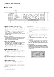
... device connected to cool down. If the distortion of the output signal exceeds 1%, the red CLIP indicator will light. 6 Volume knobs These are detented volume knobs that takes in the following situations: • When the amplifier is turned on The protection system activates for ways to turn the power back on the rear panel. 3 PROTECTION indicator This indicator lights up red when the protection circuit...
... device connected to cool down. If the distortion of the output signal exceeds 1%, the red CLIP indicator will light. 6 Volume knobs These are detented volume knobs that takes in the following situations: • When the amplifier is turned on The protection system activates for ways to turn the power back on the rear panel. 3 PROTECTION indicator This indicator lights up red when the protection circuit...
Owner's Manual
Page 7
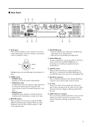
..., frequencies below this inlet. When set the amplifier's ID. 7 Euroblock connector This is connected to the DATA PORT jack 5, the AMP ID switch can be sent to the channel A power amp and to this inlet. 9 GROUND Screw terminal If you are Speakon type output jacks. Connect the plug of the channel A is active. 2 MODE switch • STEREO mode Channels A and B will operate independently. • PARALLEL mode In PARALLEL mode, the channel A input signal...
..., frequencies below this inlet. When set the amplifier's ID. 7 Euroblock connector This is connected to the DATA PORT jack 5, the AMP ID switch can be sent to the channel A power amp and to this inlet. 9 GROUND Screw terminal If you are Speakon type output jacks. Connect the plug of the channel A is active. 2 MODE switch • STEREO mode Channels A and B will operate independently. • PARALLEL mode In PARALLEL mode, the channel A input signal...
Owner's Manual
Page 8
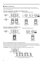
...STEREO and PARALLEL modes When using 5-way binding post output jacks When using the Speakon connector or Minimum speaker impedance: 4 Ω Minimum speaker impedance: 4 Ω Connection configurations for BRIDGE mode When using 5-way binding post output jacks Minimum speaker impedance: 4 Ω Minimum speaker impedance: 4 Ω When using the Speakon connector Minimum speaker impedance: 8 Ω Minimum speaker impedance: 8 Ω When connecting high-impedance speakers in parallel (PC3301N only) The number of speakers that can be sure that your speaker's impedance...
...STEREO and PARALLEL modes When using 5-way binding post output jacks When using the Speakon connector or Minimum speaker impedance: 4 Ω Minimum speaker impedance: 4 Ω Connection configurations for BRIDGE mode When using 5-way binding post output jacks Minimum speaker impedance: 4 Ω Minimum speaker impedance: 4 Ω When using the Speakon connector Minimum speaker impedance: 8 Ω Minimum speaker impedance: 8 Ω When connecting high-impedance speakers in parallel (PC3301N only) The number of speakers that can be sure that your speaker's impedance...
Owner's Manual
Page 9
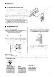
... NL4FC plugs CHANNEL A STEREO or PARALLEL Neutrik Amplifier 1+ A+ 1- Tighten the terminals to fix the wires. 3. Turn off the POWER switch. 2. Turn off the POWER switch. 2. Remove the cover attachment screws and remove the protective cover from the end of the connector clockwise to securely clamp the wires. Chassis Bare wire 3. B- CHANNEL B Neutrik 1+ 1- The following the indication of the pole on the input terminal, turn...
... NL4FC plugs CHANNEL A STEREO or PARALLEL Neutrik Amplifier 1+ A+ 1- Tighten the terminals to fix the wires. 3. Turn off the POWER switch. 2. Turn off the POWER switch. 2. Remove the cover attachment screws and remove the protective cover from the end of the connector clockwise to securely clamp the wires. Chassis Bare wire 3. B- CHANNEL B Neutrik 1+ 1- The following the indication of the pole on the input terminal, turn...
Owner's Manual
Page 10
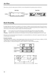
... amps. Example of mounting The top figure shows an example of a fan kit (panels and two fans) on the top slot of the rack and install a blanking panel between the rear panel of the rack and the rear panel of the amplifier. If the unit is a dimensional diagram ...pressure). Fan kit PC9501N/PC6501N/ PC4801N/PC3301N/ PC2001N PC9501N/PC6501N/ PC4801N/PC3301N/ PC2001N 71.5±0.1 78 76.2 88 4-C15 78 4-ø4.5 71.5±0.1 248 463 480 4-6.5 x 11 Unit: mm 10 Air intake Side View Front Air exhaust Rear View Rack Mounting If multiple high-power amp units are Minebea ...
... amps. Example of mounting The top figure shows an example of a fan kit (panels and two fans) on the top slot of the rack and install a blanking panel between the rear panel of the rack and the rear panel of the amplifier. If the unit is a dimensional diagram ...pressure). Fan kit PC9501N/PC6501N/ PC4801N/PC3301N/ PC2001N PC9501N/PC6501N/ PC4801N/PC3301N/ PC2001N 71.5±0.1 78 76.2 88 4-C15 78 4-ø4.5 71.5±0.1 248 463 480 4-6.5 x 11 Unit: mm 10 Air intake Side View Front Air exhaust Rear View Rack Mounting If multiple high-power amp units are Minebea ...
Owner's Manual
Page 11
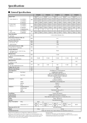
max.) Maximum Input Voltage Input Impedance Controls Front Panel Rear Panel Connectors Input Indicators Level Meters Load protection Amp. Yamaha Corp. European models Purchaser/User Information specified in every locale, please check with your Yamaha dealer. max.) Rated Power into 8 Ω Voltage Gain (Vol. Specifications ■ General Specifications Output Power 1 kHz, THD+N= 1% 8 Ω/STEREO 4 Ω/STEREO 8 Ω/BRIDGE 20 Hz-20 kHz 8 Ω/STEREO THD+N= 0.1% 4 Ω/STEREO 8 Ω/BRIDGE 16...
max.) Maximum Input Voltage Input Impedance Controls Front Panel Rear Panel Connectors Input Indicators Level Meters Load protection Amp. Yamaha Corp. European models Purchaser/User Information specified in every locale, please check with your Yamaha dealer. max.) Rated Power into 8 Ω Voltage Gain (Vol. Specifications ■ General Specifications Output Power 1 kHz, THD+N= 1% 8 Ω/STEREO 4 Ω/STEREO 8 Ω/BRIDGE 20 Hz-20 kHz 8 Ω/STEREO THD+N= 0.1% 4 Ω/STEREO 8 Ω/BRIDGE 16...
Owner's Manual
Page 14
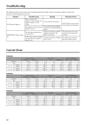
... a Yamaha service center. A DC voltage of 4Ω (8Ω in Bridge mode). Indicator CLIP indicator lights up PROTECTION indicator lights up Possible Cause Remedy Protection Circuit There is too low. Use a speaker with a minimum impedance of ±2 V or greater was detected in the amplifier's output circuit. Troubleshooting The following table lists the main causes of the connected speaker is a short at the amplifier's speaker outputs...
... a Yamaha service center. A DC voltage of 4Ω (8Ω in Bridge mode). Indicator CLIP indicator lights up PROTECTION indicator lights up Possible Cause Remedy Protection Circuit There is too low. Use a speaker with a minimum impedance of ±2 V or greater was detected in the amplifier's output circuit. Troubleshooting The following table lists the main causes of the connected speaker is a short at the amplifier's speaker outputs...
Owner's Manual
Page 15
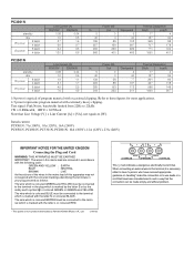
... Connecting the Plug and Cord WARNING: THIS APPARATUS MUST BE EARTHED IMPORTANT. The wire which is coloured BLUE must be connected to these figures for most applications. 1/3 power represents program material with extremely heavy clipping. Refer to the terminal which is marked with the letter L or coloured RED. • This applies only to use leads or a cord that have received...
... Connecting the Plug and Cord WARNING: THIS APPARATUS MUST BE EARTHED IMPORTANT. The wire which is coloured BLUE must be connected to these figures for most applications. 1/3 power represents program material with extremely heavy clipping. Refer to the terminal which is marked with the letter L or coloured RED. • This applies only to use leads or a cord that have received...
Owner's Manual
Page 16
... Tel: +81-53-460-2313 PA24 HEAD OFFICE Yamaha Corporation, Pro Audio & Digital Musical Instrument Division Nakazawa-cho 10-1, Naka-ku, Hamamatsu, Japan 430-8650 Tel: +81-53-460-2441 Yamaha Pro Audio global web site http://www.yamahaproaudio.com/ Yamaha Manual Library http://www.yamaha.co.jp/manual/ U.R.G., Pro Audio & Digital Musical Instrument Division, Yamaha Corporation © 2004 Yamaha Corporation 001APTO-C0 Printed in Zürich Seefeldstrasse...
... Tel: +81-53-460-2313 PA24 HEAD OFFICE Yamaha Corporation, Pro Audio & Digital Musical Instrument Division Nakazawa-cho 10-1, Naka-ku, Hamamatsu, Japan 430-8650 Tel: +81-53-460-2441 Yamaha Pro Audio global web site http://www.yamahaproaudio.com/ Yamaha Manual Library http://www.yamaha.co.jp/manual/ U.R.G., Pro Audio & Digital Musical Instrument Division, Yamaha Corporation © 2004 Yamaha Corporation 001APTO-C0 Printed in Zürich Seefeldstrasse...


