

PGM1/PGX1 Installation Manual
Page 2
... try to eliminate the problem by the FCC, to use of other electronic devices. Modifications not expressly approved by Yamaha may void your use the product. 2. CAN ICES-3 (B)/NMB-3(B) (can_b_02) B (class b korea) 2 PGM1/PGX1 Installation Manual FCC INFORMATION (U.S.A.) 1. Cable/s supplied with other electronic devices. Utilize power outlets that interference will not result in to the operation of this device must accept...
... try to eliminate the problem by the FCC, to use of other electronic devices. Modifications not expressly approved by Yamaha may void your use the product. 2. CAN ICES-3 (B)/NMB-3(B) (can_b_02) B (class b korea) 2 PGM1/PGX1 Installation Manual FCC INFORMATION (U.S.A.) 1. Cable/s supplied with other electronic devices. Utilize power outlets that interference will not result in to the operation of this device must accept...
PGM1/PGX1 Installation Manual
Page 3
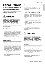
... listed below to avoid the possibility of physical injury to you notice any abnormality • If any of the PoE injector or the PoE network switch immediately and unplug the cable. PGM1/PGX1 Installation Manual 3 There is a sudden loss of sound during use it might spill into any liquid such as water seeps into the device, turn off the power...
... listed below to avoid the possibility of physical injury to you notice any abnormality • If any of the PoE injector or the PoE network switch immediately and unplug the cable. PGM1/PGX1 Installation Manual 3 There is a sudden loss of sound during use it might spill into any liquid such as water seeps into the device, turn off the power...
PGM1/PGX1 Installation Manual
Page 4
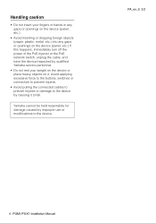
Avoid applying excessive force to the buttons, switches or connectors to prevent injuries. • Avoid pulling the connected cables to prevent injuries or damage to the device by improper use or modifications to fall. Yamaha cannot be held responsible for damage caused by causing it . PA_en_8 2/2 4 PGM1/PGX1 Installation Manual Handling caution • Do not insert your fingers or hands in...
Avoid applying excessive force to the buttons, switches or connectors to prevent injuries. • Avoid pulling the connected cables to prevent injuries or damage to the device by improper use or modifications to fall. Yamaha cannot be held responsible for damage caused by causing it . PA_en_8 2/2 4 PGM1/PGX1 Installation Manual Handling caution • Do not insert your fingers or hands in...
PGM1/PGX1 Installation Manual
Page 5
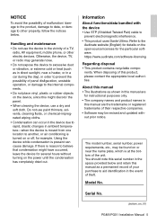
... companies. • Software may be found on the power until the condensation has completely dried out. If there is at the bottom of panel disfiguration, unstable operation, or damage to prevent electromagnetic interference. • This product uses Dante Ultimo. Information About functions/data bundled with the device • Use STP (Shielded Twisted Pair) cable to the internal components. • Do...
... companies. • Software may be found on the power until the condensation has completely dried out. If there is at the bottom of panel disfiguration, unstable operation, or damage to prevent electromagnetic interference. • This product uses Dante Ultimo. Information About functions/data bundled with the device • Use STP (Shielded Twisted Pair) cable to the internal components. • Do...
PGM1/PGX1 Installation Manual
Page 6
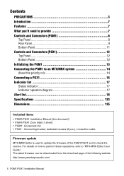
... Status indicator 17 Indicator operation diagram 17 Alert list 18 Specifications 133 Dimensions 135 Included items • PGM1/PGX1 Installation Manual (this document) • PGM1/PGX1 Zone label (1 sheet) • PGM1: Gooseneck mic • PGX1: Connecting bracket, dedicated screws (8 pcs.), connection cable Firmware update MTX-MRX Editor is used to update the firmware of the following website. For details on how to perform these operations, refer to "MTX-MRX Editor User Guide."
... Status indicator 17 Indicator operation diagram 17 Alert list 18 Specifications 133 Dimensions 135 Included items • PGM1/PGX1 Installation Manual (this document) • PGM1/PGX1 Zone label (1 sheet) • PGM1: Gooseneck mic • PGX1: Connecting bracket, dedicated screws (8 pcs.), connection cable Firmware update MTX-MRX Editor is used to update the firmware of the following website. For details on how to perform these operations, refer to "MTX-MRX Editor User Guide."

PGM1/PGX1 Installation Manual
Page 7
... you for the installing technician or the designer. This installation manual explains installation methods for purchasing the Yamaha PGM1 paging station microphone or the PGX1 paging station extension. They provide the following features. • Paging stations can be networked via a Dante network and PoE (Power over Ethernet). • Chimes and messages can be played back using an SD card player. • Two...
... you for the installing technician or the designer. This installation manual explains installation methods for purchasing the Yamaha PGM1 paging station microphone or the PGX1 paging station extension. They provide the following features. • Paging stations can be networked via a Dante network and PoE (Power over Ethernet). • Chimes and messages can be played back using an SD card player. • Two...
PGM1/PGX1 Installation Manual
Page 8
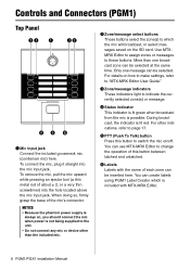
... (PGM1) Top Panel we q ew rt y q Mic input jack Connect the included gooseneck mic (condenser mic) here. For details on the SD card. When doing so, firmly grasp the base of each zone can be inserted here. During broadcast, the indicator is not being supplied to the unit. • Do not connect any mic or device other indications, refer to "MTX-MRX Editor User Guide."
... (PGM1) Top Panel we q ew rt y q Mic input jack Connect the included gooseneck mic (condenser mic) here. For details on the SD card. When doing so, firmly grasp the base of each zone can be inserted here. During broadcast, the indicator is not being supplied to the unit. • Do not connect any mic or device other indications, refer to "MTX-MRX Editor User Guide."
PGM1/PGX1 Installation Manual
Page 9
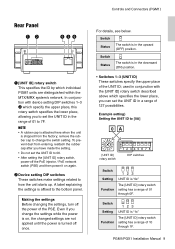
..., you change the switch setting. remove the rubber cap to the bottom panel. Making the settings Before changing the settings, turn off the PoE injector / PoE network switch (PSE) and then power it on , the changed settings are distinguished within the MTX/MRX system's network. Controls and Connectors (PGM1) For details, see below. Switch Setting 123 UNIT ID is "1x" Function The [UNIT ID] rotary switch setting has a range...
..., you change the switch setting. remove the rubber cap to the bottom panel. Making the settings Before changing the settings, turn off the PoE injector / PoE network switch (PSE) and then power it on , the changed settings are distinguished within the MTX/MRX system's network. Controls and Connectors (PGM1) For details, see below. Switch Setting 123 UNIT ID is "1x" Function The [UNIT ID] rotary switch setting has a range...

PGM1/PGX1 Installation Manual
Page 10
... Editor User Guide"). Also, if you connect this unit to "PC." 10 PGM1/PGX1 Installation Manual Switch Setting 123 UNIT ID is "6x" Function The [UNIT ID] rotary switch setting has a range of 20 through 2F. Switch Setting 123 UNIT ID is "5x" Function The [UNIT ID] rotary switch setting has a range of 30 through 5F. Switch Setting 123 UNIT ID is "3x" Function The [UNIT ID] rotary switch setting has...
... Editor User Guide"). Also, if you connect this unit to "PC." 10 PGM1/PGX1 Installation Manual Switch Setting 123 UNIT ID is "6x" Function The [UNIT ID] rotary switch setting has a range of 20 through 2F. Switch Setting 123 UNIT ID is "5x" Function The [UNIT ID] rotary switch setting has a range of 30 through 5F. Switch Setting 123 UNIT ID is "3x" Function The [UNIT ID] rotary switch setting has...
PGM1/PGX1 Installation Manual
Page 11
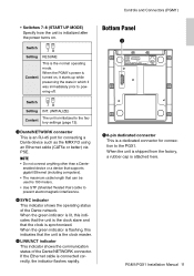
...-45 port for connection to the factory settings (page 13). When the green indicator is lit, this indicates that the unit is 100 meters. • Use STP (Shielded Twisted Pair) cable to powering-off. When the green indicator is flashing, this indicates that the unit is the clock slave and that can be used is the clock master. PGM1/PGX1 Installation Manual 11 Switch Setting 78 INT...
...-45 port for connection to the factory settings (page 13). When the green indicator is lit, this indicates that the unit is 100 meters. • Use STP (Shielded Twisted Pair) cable to powering-off. When the green indicator is flashing, this indicates that the unit is the clock slave and that can be used is the clock master. PGM1/PGX1 Installation Manual 11 Switch Setting 78 INT...
PGM1/PGX1 Installation Manual
Page 12
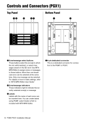
... connection to "MTX-MRX Editor User Guide." You can be selected at the same time. More than one message can be inserted here. e Labels Labels with the name of each zone can create labels using PGM1 Label Creator which the mic will broadcast, or select messages saved on how to make settings, refer to the PGM1 or PGX1. 12 PGM1/PGX1 Installation Manual...
... connection to "MTX-MRX Editor User Guide." You can be selected at the same time. More than one message can be inserted here. e Labels Labels with the name of each zone can create labels using PGM1 Label Creator which the mic will broadcast, or select messages saved on how to make settings, refer to the PGM1 or PGX1. 12 PGM1/PGX1 Installation Manual...
PGM1/PGX1 Installation Manual
Page 13
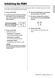
... initialization is completed, and then power-off the PSE. 2. PGM1/PGX1 Installation Manual 13 Set device settings DIP switches 7 and 8 both to the downward position, and set state, for example because the installation location has changed, proceed as follows. 1. Power-on the PSE. Power-on the PSE. On the rear panel, set device settings DIP switch 7 to the upward (RESUME) position. The unit starts up in the factory-set state.
... initialization is completed, and then power-off the PSE. 2. PGM1/PGX1 Installation Manual 13 Set device settings DIP switches 7 and 8 both to the downward position, and set state, for example because the installation location has changed, proceed as follows. 1. Power-on the PSE. Power-on the PSE. On the rear panel, set device settings DIP switch 7 to the upward (RESUME) position. The unit starts up in the factory-set state.

PGM1/PGX1 Installation Manual
Page 14
NOTICE Do not connect or disconnect cables while the PSE is on. 14 PGM1/PGX1 Installation Manual Within the group, mics other mics in the group are given first-come first-served priority. Group 1 MRX7-D ID=01 P PGM1 ID=60 PGX1 ID=0 PGX1 ID=1 PGM1 ID=61 PGX1 ID=0 PGX1 ID=1 SWR2100P-10G Group 2 MTX5-D ID=02 PGM1 ID=62 P PGM1 ID=63 PGX1 ID=0 PGX1...
NOTICE Do not connect or disconnect cables while the PSE is on. 14 PGM1/PGX1 Installation Manual Within the group, mics other mics in the group are given first-come first-served priority. Group 1 MRX7-D ID=01 P PGM1 ID=60 PGX1 ID=0 PGX1 ID=1 PGM1 ID=61 PGX1 ID=0 PGX1 ID=1 SWR2100P-10G Group 2 MTX5-D ID=02 PGM1 ID=62 P PGM1 ID=63 PGX1 ID=0 PGX1...
PGM1/PGX1 Installation Manual
Page 15
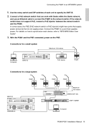
... have ports that supply power and ports that can work with Dante within the Dante network, and use an Ethernet cable to connect the PGM1 to the network switch. Connections for a small system Maximum 100 meters Computer MRX7-D PoE injector PGM1 Connections for a large system PGM1 PGM1 PGM1 PGM1 MRX7-D Maximum 100 meters SWR2100P-10G SWP1-16MMF XMV8280-D Computer PGM1/PGX1 Installation Manual 15 Use the rotary switch and DIP switches of each...
... have ports that supply power and ports that can work with Dante within the Dante network, and use an Ethernet cable to connect the PGM1 to the network switch. Connections for a small system Maximum 100 meters Computer MRX7-D PoE injector PGM1 Connections for a large system PGM1 PGM1 PGM1 PGM1 MRX7-D Maximum 100 meters SWR2100P-10G SWP1-16MMF XMV8280-D Computer PGM1/PGX1 Installation Manual 15 Use the rotary switch and DIP switches of each...

PGM1/PGX1 Installation Manual
Page 16
... to secure it. NOTICE • Before making connections, detach the Ethernet cable and gooseneck mic. • Make sure to place a soft cloth underneath the device so that you can be connected to one PGM1 unit. Use the included connection cable to connect the PGM1 and PGX1. Connecting a PGX1 Up to two PGX1 units can do so in a similar way. 16 PGM1/PGX1 Installation Manual
... to secure it. NOTICE • Before making connections, detach the Ethernet cable and gooseneck mic. • Make sure to place a soft cloth underneath the device so that you can be connected to one PGM1 unit. Use the included connection cable to connect the PGM1 and PGX1. Connecting a PGX1 Up to two PGX1 units can do so in a similar way. 16 PGM1/PGX1 Installation Manual

PGM1/PGX1 Installation Manual
Page 17
PTT: ON PTT: OFF PTT indicator (mic being operated) Green (Preparing) Flashing red (Broadcasting) Red Green Program Output Level 0 db Chime (SD) Mic Output/ Message (SD) Mic Input SD Input Range -∞ Attack Opening Chime PTT indicator Green (mic not being operated) Orange Closing Release Chime Green Time PGM1/PGX1 Installation Manual 17 Indicator list Status indicator Lit green Lit orange Lit red Flashing red Flashing orange Broadcast is possible Broadcast is...
PTT: ON PTT: OFF PTT indicator (mic being operated) Green (Preparing) Flashing red (Broadcasting) Red Green Program Output Level 0 db Chime (SD) Mic Output/ Message (SD) Mic Input SD Input Range -∞ Attack Opening Chime PTT indicator Green (mic not being operated) Orange Closing Release Chime Green Time PGM1/PGX1 Installation Manual 17 Indicator list Status indicator Lit green Lit orange Lit red Flashing red Flashing orange Broadcast is possible Broadcast is...
PGM1/PGX1 Installation Manual
Page 18
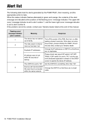
... this also fails, contact your Yamaha dealer listed at least 6 seconds. Please check rear panel DIP switch 6 (IP SETTING). When the status indicator flashes alternately in internal memory has been lost. The UNIT ID is set to alert number 8. Set the UNIT ID to take. Change the UNIT ID so that there are no duplicates. 18 PGM1/PGX1 Installation Manual Change the IP addresses or UNIT ID...
... this also fails, contact your Yamaha dealer listed at least 6 seconds. Please check rear panel DIP switch 6 (IP SETTING). When the status indicator flashes alternately in internal memory has been lost. The UNIT ID is set to alert number 8. Set the UNIT ID to take. Change the UNIT ID so that there are no duplicates. 18 PGM1/PGX1 Installation Manual Change the IP addresses or UNIT ID...

PGM1/PGX1 Installation Manual
Page 20
Conforms to Environments: E1, E2, E3 and E4 134 PGM1/PGX1 Installation Manual European models Purchaser/User Information specified in EN55103-2:2009.
Conforms to Environments: E1, E2, E3 and E4 134 PGM1/PGX1 Installation Manual European models Purchaser/User Information specified in EN55103-2:2009.

PGM1/PGX1 Installation Manual
Page 23
PGM1/PGX1 Installation Manual 137
PGM1/PGX1 Installation Manual 137


