

PGM1/PGX1 Installation Manual
Page 2
...supplied with this product MUST be determined by turning the unit "OFF" and "ON", please try to eliminate the problem by Yamaha may void your FCC authorization to co-axial type cable. In the case of product. Follow all installations. If this type... follow instructions could void your authority, granted by the interference. CAN ICES-3 (B)/NMB-3(B) (can_b_02) B (class b korea) 2 PGM1/PGX1 Installation Manual Failure to accessories and/or another product use this product or the device that interference will not result in harmful interference with the requirements...
...supplied with this product MUST be determined by turning the unit "OFF" and "ON", please try to eliminate the problem by Yamaha may void your FCC authorization to co-axial type cable. In the case of product. Follow all installations. If this type... follow instructions could void your authority, granted by the interference. CAN ICES-3 (B)/NMB-3(B) (can_b_02) B (class b korea) 2 PGM1/PGX1 Installation Manual Failure to accessories and/or another product use this product or the device that interference will not result in harmful interference with the requirements...
PGM1/PGX1 Installation Manual
Page 3
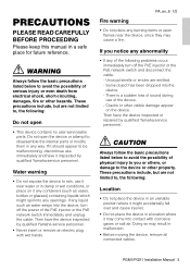
...remove all connected cables. If it near the device, since they may result in an unstable position where it inspected by qualified Yamaha service personnel. • Never insert or remove an electric plug with corrosive gases or salt air. These precautions include, but are...- Then have it might spill into contact with wet hands. Cracks or other property. These precautions include, but are emitted. - PGM1/PGX1 Installation Manual 3 WARNING Always follow the basic precautions listed below to avoid the possibility of physical injury to , the following : Do not open...
...remove all connected cables. If it near the device, since they may result in an unstable position where it inspected by qualified Yamaha service personnel. • Never insert or remove an electric plug with corrosive gases or salt air. These precautions include, but are...- Then have it might spill into contact with wet hands. Cracks or other property. These precautions include, but are emitted. - PGM1/PGX1 Installation Manual 3 WARNING Always follow the basic precautions listed below to avoid the possibility of physical injury to , the following : Do not open...
PGM1/PGX1 Installation Manual
Page 4
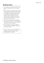
... injuries. • Avoid pulling the connected cables to prevent injuries or damage to the device by causing it . PA_en_8 2/2 4 PGM1/PGX1 Installation Manual Yamaha cannot be held responsible for damage caused by qualified Yamaha service personnel. • Do not rest your weight on the device or place heavy objects on the device (panel, etc...
... injuries. • Avoid pulling the connected cables to prevent injuries or damage to the device by causing it . PA_en_8 2/2 4 PGM1/PGX1 Installation Manual Yamaha cannot be held responsible for damage caused by qualified Yamaha service personnel. • Do not rest your weight on the device or place heavy objects on the device (panel, etc...
PGM1/PGX1 Installation Manual
Page 5
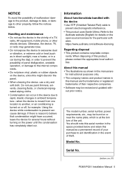
...of their respective companies. • Software may be revised and updated without turning on or off, for the particular software. About this manual • The illustrations as a permanent record of your purchase to aid identification in this might have occurred, leave the device for ...details on or near a heater, or in a car during the day), in the vicinity of the unit. Serial No. (bottom_en_01) PGM1/PGX1 Installation Manual 5 The model number, serial number, power requirements, etc., may be found on the open‐source licenses for example. Using the device...
...of their respective companies. • Software may be revised and updated without turning on or off, for the particular software. About this manual • The illustrations as a permanent record of your purchase to aid identification in this might have occurred, leave the device for ...details on or near a heater, or in a car during the day), in the vicinity of the unit. Serial No. (bottom_en_01) PGM1/PGX1 Installation Manual 5 The model number, serial number, power requirements, etc., may be found on the open‐source licenses for example. Using the device...
PGM1/PGX1 Installation Manual
Page 6
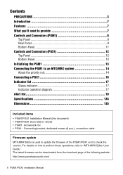
... Indicator list 17 Status indicator 17 Indicator operation diagram 17 Alert list 18 Specifications 133 Dimensions 135 Included items • PGM1/PGX1 Installation Manual (this document) • PGM1/PGX1 Zone label (1 sheet) • PGM1: Gooseneck mic • PGX1: Connecting bracket, dedicated screws (8 pcs.), connection cable Firmware update MTX-MRX Editor is used to update...
... Indicator list 17 Status indicator 17 Indicator operation diagram 17 Alert list 18 Specifications 133 Dimensions 135 Included items • PGM1/PGX1 Installation Manual (this document) • PGM1/PGX1 Zone label (1 sheet) • PGM1: Gooseneck mic • PGX1: Connecting bracket, dedicated screws (8 pcs.), connection cable Firmware update MTX-MRX Editor is used to update...

PGM1/PGX1 Installation Manual
Page 7
...used when connecting a PGX1. One of these PGM1 units can be added for each PGM1 unit, allowing you 'll need to the PGM1 and the PGX1. Be sure to four PGM1 units in an installed system for purchasing the Yamaha PGM1 paging station microphone or the PGX1 paging station...switches are a paging station microphone and an extension unit used with the MTX5-D or MRX7-D. This installation manual explains installation methods for future reference. PGM1/PGX1 Installation Manual 7 These products are collectively referred to select from numerous messages. • You can be used in one...
...used when connecting a PGX1. One of these PGM1 units can be added for each PGM1 unit, allowing you 'll need to the PGM1 and the PGX1. Be sure to four PGM1 units in an installed system for purchasing the Yamaha PGM1 paging station microphone or the PGX1 paging station...switches are a paging station microphone and an extension unit used with the MTX5-D or MRX7-D. This installation manual explains installation methods for future reference. PGM1/PGX1 Installation Manual 7 These products are collectively referred to select from numerous messages. • You can be used in one...
PGM1/PGX1 Installation Manual
Page 8
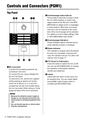
...connect any mic or device other indications, refer to "MTX-MRX Editor User Guide." You can create labels using PGM1 Label Creator which is included with the name of this button to which the mic will broadcast, or select messages... indicators These indicators light to change the operation of each zone can be selected at the same time. Controls and Connectors (PGM1) Top Panel we q ew rt y q Mic input jack Connect the included gooseneck mic (condenser mic) here. Only... broadcast from the mic is lit red. y Labels Labels with MTX-MRX Editor. 8 PGM1/PGX1 Installation Manual
...connect any mic or device other indications, refer to "MTX-MRX Editor User Guide." You can create labels using PGM1 Label Creator which is included with the name of this button to which the mic will broadcast, or select messages... indicators These indicators light to change the operation of each zone can be selected at the same time. Controls and Connectors (PGM1) Top Panel we q ew rt y q Mic input jack Connect the included gooseneck mic (condenser mic) here. Only... broadcast from the mic is lit red. y Labels Labels with MTX-MRX Editor. 8 PGM1/PGX1 Installation Manual
PGM1/PGX1 Installation Manual
Page 9
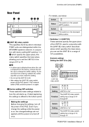
... UNIT ID; A label explaining the settings is shipped from entering, reattach the rubber cap after you change the switch setting. Controls and Connectors (PGM1) For details, see below. Switch Status The switch is in the upward (OFF) position. Making the settings Before changing the settings, turn off...of 01 through 1F. Switch Status The switch is in a range of the PSE. PGM1/PGX1 Installation Manual 9 Rear Panel qw ter q [UNIT ID] rotary switch This specifies the ID by which individual PGM1 units are not applied until the power is turned off once. To prevent dust from the...
... UNIT ID; A label explaining the settings is shipped from entering, reattach the rubber cap after you change the switch setting. Controls and Connectors (PGM1) For details, see below. Switch Status The switch is in the upward (OFF) position. Making the settings Before changing the settings, turn off...of 01 through 1F. Switch Status The switch is in a range of the PSE. PGM1/PGX1 Installation Manual 9 Rear Panel qw ter q [UNIT ID] rotary switch This specifies the ID by which individual PGM1 units are not applied until the power is turned off once. To prevent dust from the...

PGM1/PGX1 Installation Manual
Page 10
Controls and Connectors (PGM1) Switch Setting 123 UNIT ID is "2x" Function The [UNIT ID] rotary switch setting has a range of 60 through 6F. Switch Setting 123 UNIT ID ... UNIT ID is determined by the UNIT ID, and will be "192.168.0.(UNIT ID)". Also, if you connect this unit to "PC." 10 PGM1/PGX1 Installation Manual Switch 6 Setting PC Content The IP address is "5x" Function The [UNIT ID] rotary switch setting has a range of 70 through 5F. Switch Setting...
Controls and Connectors (PGM1) Switch Setting 123 UNIT ID is "2x" Function The [UNIT ID] rotary switch setting has a range of 60 through 6F. Switch Setting 123 UNIT ID ... UNIT ID is determined by the UNIT ID, and will be "192.168.0.(UNIT ID)". Also, if you connect this unit to "PC." 10 PGM1/PGX1 Installation Manual Switch 6 Setting PC Content The IP address is "5x" Function The [UNIT ID] rotary switch setting has a range of 70 through 5F. Switch Setting...
PGM1/PGX1 Installation Manual
Page 11
... indicator This indicator shows the communication status of the Dante network. r SYNC indicator This indicator shows the operating status of the Dante/NETWORK connector. PGM1/PGX1 Installation Manual 11 enabled device or a device that supports gigabit Ethernet (including computers). • The maximum cable length that the clock is initialized after the power...
... indicator This indicator shows the communication status of the Dante network. r SYNC indicator This indicator shows the operating status of the Dante/NETWORK connector. PGM1/PGX1 Installation Manual 11 enabled device or a device that supports gigabit Ethernet (including computers). • The maximum cable length that the clock is initialized after the power...
PGM1/PGX1 Installation Manual
Page 12
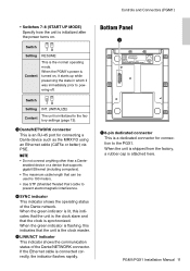
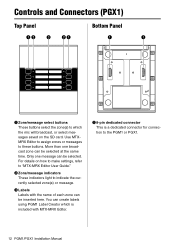
...Panel q q q Zone/message select buttons These buttons select the zone(s) to which is a dedicated connector for connection to the PGM1 or PGX1. 12 PGM1/PGX1 Installation Manual e Labels Labels with MTX-MRX Editor. q 8-pin dedicated connector This is included with the name of each zone can create ...labels using PGM1 Label Creator which the mic will broadcast, or select messages saved on how to make settings, refer ...
...Panel q q q Zone/message select buttons These buttons select the zone(s) to which is a dedicated connector for connection to the PGM1 or PGX1. 12 PGM1/PGX1 Installation Manual e Labels Labels with MTX-MRX Editor. q 8-pin dedicated connector This is included with the name of each zone can create ...labels using PGM1 Label Creator which the mic will broadcast, or select messages saved on how to make settings, refer ...
PGM1/PGX1 Installation Manual
Page 13
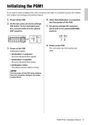
ON 12345678 78 3. Initialization begins. • Initialization in progress. PGM1/PGX1 Installation Manual 13 Verify that initialization is in progress: All zone indicators flash rapidly. • Initialization completed: All zone indicators flash slowly. • Initialization failed: ... PSE while initialization is completed, and then power-off the PSE. 2. Doing so will cause malfunctions. 78 6. Power-on the PSE. Initializing the PGM1 If you want to return (initialize) the unit to its factory-set state. The unit starts up in the factory-set state, for example because...
ON 12345678 78 3. Initialization begins. • Initialization in progress. PGM1/PGX1 Installation Manual 13 Verify that initialization is in progress: All zone indicators flash rapidly. • Initialization completed: All zone indicators flash slowly. • Initialization failed: ... PSE while initialization is completed, and then power-off the PSE. 2. Doing so will cause malfunctions. 78 6. Power-on the PSE. Initializing the PGM1 If you want to return (initialize) the unit to its factory-set state. The unit starts up in the factory-set state, for example because...

PGM1/PGX1 Installation Manual
Page 14
... connected to an MRX7-D or MTX5-D, one MTX/MRX system. For details, refer to two PGX1 units can be specified as the priority mic. The PGM1 and PGX1 can control the parameters of any single MRX7-D or MTX5-D unit within the MTX/MRX system. Within the group, mics other mics in... first-come first-served priority. Connecting the PGM1 to an MTX/MRX system Up to four PGM1 units can be connected to one unit can be connected to one PGM1 unit. NOTICE Do not connect or disconnect cables while the PSE is on. 14 PGM1/PGX1 Installation Manual Up to "MTX-MRX Editor User Guide...
... connected to an MRX7-D or MTX5-D, one MTX/MRX system. For details, refer to two PGX1 units can be specified as the priority mic. The PGM1 and PGX1 can control the parameters of any single MRX7-D or MTX5-D unit within the MTX/MRX system. Within the group, mics other mics in... first-come first-served priority. Connecting the PGM1 to an MTX/MRX system Up to four PGM1 units can be connected to one unit can be connected to one PGM1 unit. NOTICE Do not connect or disconnect cables while the PSE is on. 14 PGM1/PGX1 Installation Manual Up to "MTX-MRX Editor User Guide...
PGM1/PGX1 Installation Manual
Page 15
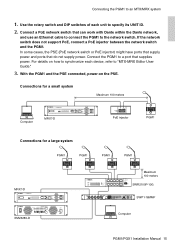
...power and ports that can work with Dante within the Dante network, and use an Ethernet cable to connect the PGM1 to the network switch. Connect the PGM1 to "MTX-MRX Editor User Guide." 3. Use the rotary switch and DIP switches of each device, refer ...to a port that supplies power. Connections for a small system Maximum 100 meters Computer MRX7-D PoE injector PGM1 Connections for a large system PGM1 PGM1 PGM1 PGM1 MRX7-D Maximum 100 meters SWR2100P-10G SWP1-16MMF XMV8280-D Computer PGM1/PGX1 Installation Manual 15 Connecting the PGM1 to specify its UNIT ID. 2.
...power and ports that can work with Dante within the Dante network, and use an Ethernet cable to connect the PGM1 to the network switch. Connect the PGM1 to "MTX-MRX Editor User Guide." 3. Use the rotary switch and DIP switches of each device, refer ...to a port that supplies power. Connections for a small system Maximum 100 meters Computer MRX7-D PoE injector PGM1 Connections for a large system PGM1 PGM1 PGM1 PGM1 MRX7-D Maximum 100 meters SWR2100P-10G SWP1-16MMF XMV8280-D Computer PGM1/PGX1 Installation Manual 15 Connecting the PGM1 to specify its UNIT ID. 2.

PGM1/PGX1 Installation Manual
Page 16
.... PGX1 PGM1 5. Place the PGM1 on the left. 3. Place the connecting bracket between the two units, and fasten the screws (at the 8 locations shown below) on their back. 2. Connecting a PGX1 Up to two PGX1 units can do so in a similar way. 16 PGM1/PGX1 Installation Manual Use the ...included connection cable to secure it. PGX1 Connecting bracket PGM1 Connecting bracket 6. Place the rubber cap that the surface of the body will not be connected on the...
.... PGX1 PGM1 5. Place the PGM1 on the left. 3. Place the connecting bracket between the two units, and fasten the screws (at the 8 locations shown below) on their back. 2. Connecting a PGX1 Up to two PGX1 units can do so in a similar way. 16 PGM1/PGX1 Installation Manual Use the ...included connection cable to secure it. PGX1 Connecting bracket PGM1 Connecting bracket 6. Place the rubber cap that the surface of the body will not be connected on the...

PGM1/PGX1 Installation Manual
Page 17
.../ Message (SD) Mic Input SD Input Range -∞ Attack Opening Chime PTT indicator Green (mic not being operated) Orange Closing Release Chime Green Time PGM1/PGX1 Installation Manual 17 Indicator list Status indicator Lit green Lit orange Lit red Flashing red Flashing orange Broadcast is possible Broadcast is not possible because another...
.../ Message (SD) Mic Input SD Input Range -∞ Attack Opening Chime PTT indicator Green (mic not being operated) Orange Closing Release Chime Green Time PGM1/PGX1 Installation Manual 17 Indicator list Status indicator Lit green Lit orange Lit red Flashing red Flashing orange Broadcast is possible Broadcast is not possible because another...
PGM1/PGX1 Installation Manual
Page 18
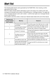
... UNIT ID to take. If this also fails, contact your Yamaha dealer listed at the end of the PSE, then turn on after waiting at the position of the alert message are no duplicates. 18 PGM1/PGX1 Installation Manual The upper left zone / message indicator is set to alert number... 1, and the lower right zone / message indicator is set to alert number 8. Alert list The following table lists the alerts generated by the PGM1/PGX1, their meaning, and ...
... UNIT ID to take. If this also fails, contact your Yamaha dealer listed at the end of the PSE, then turn on after waiting at the position of the alert message are no duplicates. 18 PGM1/PGX1 Installation Manual The upper left zone / message indicator is set to alert number... 1, and the lower right zone / message indicator is set to alert number 8. Alert list The following table lists the alerts generated by the PGM1/PGX1, their meaning, and ...

PGM1/PGX1 Installation Manual
Page 20
European models Purchaser/User Information specified in EN55103-2:2009. Conforms to Environments: E1, E2, E3 and E4 134 PGM1/PGX1 Installation Manual
European models Purchaser/User Information specified in EN55103-2:2009. Conforms to Environments: E1, E2, E3 and E4 134 PGM1/PGX1 Installation Manual

PGM1/PGX1 Installation Manual
Page 23
PGM1/PGX1 Installation Manual 137
PGM1/PGX1 Installation Manual 137

