
Owner's Manual
Page 11
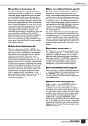
... master and matrix sections assign the oscillator and talkback signals to the corresponding output. 6 Monitor Control Section (page 40) With two monitor outputs (MONITOR A & B) and [CUE] switches on the meter bridge allow the module [CUE...while the [VCA MUTE] switches mute or un-mute the corresponding VCA groups. After going through phantom power, input gain, phase reversal, and high-pass filter stages, the audio signal passes through a...and send these signals to the stereo and mono main outputs. PM5000 Overview 1 Input Channel Section (page 15) Two types of the [MATRIX SUB IN L&R] ...
... master and matrix sections assign the oscillator and talkback signals to the corresponding output. 6 Monitor Control Section (page 40) With two monitor outputs (MONITOR A & B) and [CUE] switches on the meter bridge allow the module [CUE...while the [VCA MUTE] switches mute or un-mute the corresponding VCA groups. After going through phantom power, input gain, phase reversal, and high-pass filter stages, the audio signal passes through a...and send these signals to the stereo and mono main outputs. PM5000 Overview 1 Input Channel Section (page 15) Two types of the [MATRIX SUB IN L&R] ...

Owner's Manual
Page 12
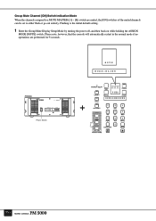
... expansion connectors. NOTE The two screws on the right side of time it interacts with the monitor control section, the meter bridge's LED bar-graph meters provide visual monitoring of the unit. The PM5000 can be used to and from the scene memory. These 8 screws do not affect the ...(CompactFlash) memory cards (see page 59). Other controls provided on /off status of this section is located on the sides of the PW5000 Power Supply unit as well as [DIRECT RECALL] switches for the console's illuminated controls and gooseneck lamps are also provided. This section also provides ...
... expansion connectors. NOTE The two screws on the right side of time it interacts with the monitor control section, the meter bridge's LED bar-graph meters provide visual monitoring of the unit. The PM5000 can be used to and from the scene memory. These 8 screws do not affect the ...(CompactFlash) memory cards (see page 59). Other controls provided on /off status of this section is located on the sides of the PW5000 Power Supply unit as well as [DIRECT RECALL] switches for the console's illuminated controls and gooseneck lamps are also provided. This section also provides ...

Owner's Manual
Page 13
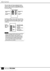
... These are the air vents for LCR monitoring (MONITOR B = Center). * Talkback/Oscillator Out The talkback or oscillator signal appears at this connector using the power supply cable supplied with the PM5000 console. 13 When using phantom power use A and B simultaneously for the console's internal cooling fans (4 locations on the PM5000-52C, 3 on all input channels. You...
... These are the air vents for LCR monitoring (MONITOR B = Center). * Talkback/Oscillator Out The talkback or oscillator signal appears at this connector using the power supply cable supplied with the PM5000 console. 13 When using phantom power use A and B simultaneously for the console's internal cooling fans (4 locations on the PM5000-52C, 3 on all input channels. You...
Owner's Manual
Page 26
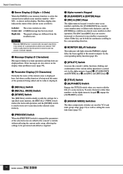
Flashing is the initial default setting. 1 Enter the Group Mute Display Setup Mode by turning the power off, and then back on while holding the ASSIGN MODE [MUTE] switch. Group Mute Channel [ON] Switch Indication Mode When the channels assigned to either &#... mode if no operations are muted, the [ON] switches of the muted channels can be set to a MUTE MASTER ([1] ~ [8]) switch are performed for 5 seconds. M U T E M O D E : B L I N K PW5000 POWER SUPPLY POWER ON OFF OPERATION MONITOR NORMAL +16 -16 CAUTION +12 +48 FAN HIGH STOP THERMAL FAN SPEED AUTO HIGH LINE VOLTAGE...
Flashing is the initial default setting. 1 Enter the Group Mute Display Setup Mode by turning the power off, and then back on while holding the ASSIGN MODE [MUTE] switch. Group Mute Channel [ON] Switch Indication Mode When the channels assigned to either &#... mode if no operations are muted, the [ON] switches of the muted channels can be set to a MUTE MASTER ([1] ~ [8]) switch are performed for 5 seconds. M U T E M O D E : B L I N K PW5000 POWER SUPPLY POWER ON OFF OPERATION MONITOR NORMAL +16 -16 CAUTION +12 +48 FAN HIGH STOP THERMAL FAN SPEED AUTO HIGH LINE VOLTAGE...
Owner's Manual
Page 50
... fans. Panel switch dimmer. Cooling fans (lights when a problem is possible, but if operation becomes impossible the power supply will light as long as operation of the PM5000's internal cooling fans ceases to operate. Monitor Control Section The meter bridge also features independent dimmer controls for the meters, panel switch illumination, and gooseneck...
... fans. Panel switch dimmer. Cooling fans (lights when a problem is possible, but if operation becomes impossible the power supply will light as long as operation of the PM5000's internal cooling fans ceases to operate. Monitor Control Section The meter bridge also features independent dimmer controls for the meters, panel switch illumination, and gooseneck...
Owner's Manual
Page 52
... fade times (page 52). 50 The three display dots indicate the status of the selected scene are displayed here. NOTE When the PM5000 power is turned on the last panel setup before it was turned off is automatically recalled (scene memory "000" will light when the...page 94). 3 Parameter Display (12 Characters) Normally the name of the current scene is displayed here, but when a utility function is being used to the monitor outputs via the corresponding utility function (page 68). @ [UTILITY] Switch Accesses the console's utility functions. Either key can be previewed and edited as required....
... fade times (page 52). 50 The three display dots indicate the status of the selected scene are displayed here. NOTE When the PM5000 power is turned on the last panel setup before it was turned off is automatically recalled (scene memory "000" will light when the...page 94). 3 Parameter Display (12 Characters) Normally the name of the current scene is displayed here, but when a utility function is being used to the monitor outputs via the corresponding utility function (page 68). @ [UTILITY] Switch Accesses the console's utility functions. Either key can be previewed and edited as required....
Owner's Manual
Page 86
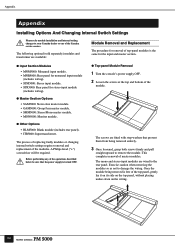
...turned OFF. ● Top-panel Module Removal 1 Turn the console's power supply OFF. 2 Loosen the screws at the top and bottom of the Yamaha service centers. Exercise caution when removing the modules so as not to your Yamaha dealer or one of the module. The process of replacing faulty modules ...; Master Section Options • SAM5000: Stereo Aux master module. • GAM5000: Group/Aux master module. • SMM5000: Stereo/Mono master module. • MON5000: Monitor module. ● Other Options • BLM5000: Blank module (includes rear panel). • ITR5000: Input transformer.
...turned OFF. ● Top-panel Module Removal 1 Turn the console's power supply OFF. 2 Loosen the screws at the top and bottom of the Yamaha service centers. Exercise caution when removing the modules so as not to your Yamaha dealer or one of the module. The process of replacing faulty modules ...; Master Section Options • SAM5000: Stereo Aux master module. • GAM5000: Group/Aux master module. • SMM5000: Stereo/Mono master module. • MON5000: Monitor module. ● Other Options • BLM5000: Blank module (includes rear panel). • ITR5000: Input transformer.
Owner's Manual
Page 97
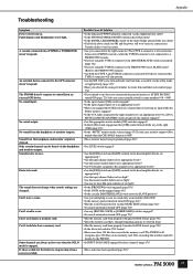
...to the right connector? The sound does not change when console settings are always active even when the SOLO mode is OFF. • Has a monitor delay been programmed (page 68)? • Is a [CUE] switch engaged? • Are the [PAD] switch and [GAIN] controls in ... won't turn on , contact your Yamaha dealer or service center. • Are you connected to the GPI connector doesn't respond. No sound output. Appendix Troubleshooting Symptom Power won 't light. A cascade-connected slave PM5000 or PM4000/3500 doesn't respond. Can't load data from an external GPI device. Is a [...
...to the right connector? The sound does not change when console settings are always active even when the SOLO mode is OFF. • Has a monitor delay been programmed (page 68)? • Is a [CUE] switch engaged? • Are the [PAD] switch and [GAIN] controls in ... won't turn on , contact your Yamaha dealer or service center. • Are you connected to the GPI connector doesn't respond. No sound output. Appendix Troubleshooting Symptom Power won 't light. A cascade-connected slave PM5000 or PM4000/3500 doesn't respond. Can't load data from an external GPI device. Is a [...
Owner's Manual
Page 98
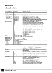
... is referenced to 0.775 Vrms. Total Harmonic Distortion (Master Output) Less than 1% T.H.D. @ +4dBu Selectable continue or BURST for powering condenser microphones via 6.8kΩ currentlimiting/isolation resistors. PEAK LED (red) turns on when pre-EQ level or post-EQ level or pre-Fader level .../AUX OUT (AUX mode & PRE) 87dB ST IN to GROUP/AUX OUT (AUX mode & POST) 10dB SUB IN to Master OUT 6dB 2TR IN to MONITOR OUT Crosstalk -80dB @ 1kHz, -70dB @ 10kHz Adjacent inputs. -80dB @ 1kHz, -70dB @ 10kHz input to balanced inputs for PINK noise by SWEEP/BURST ON/OFF switch...
... is referenced to 0.775 Vrms. Total Harmonic Distortion (Master Output) Less than 1% T.H.D. @ +4dBu Selectable continue or BURST for powering condenser microphones via 6.8kΩ currentlimiting/isolation resistors. PEAK LED (red) turns on when pre-EQ level or post-EQ level or pre-Fader level .../AUX OUT (AUX mode & PRE) 87dB ST IN to GROUP/AUX OUT (AUX mode & POST) 10dB SUB IN to Master OUT 6dB 2TR IN to MONITOR OUT Crosstalk -80dB @ 1kHz, -70dB @ 10kHz Adjacent inputs. -80dB @ 1kHz, -70dB @ 10kHz input to balanced inputs for PINK noise by SWEEP/BURST ON/OFF switch...

Owner's Manual
Page 100
... in EN55103-1 and EN55103-2. digital - digital - 3. Yamaha Corp. Others 3.1 Included Accessories Power Supply Connection Cable (3.6m) Gooseneck Lamps (4 for the PM5000-52C, 3 for information purposes only. reserves the right to... change or modify products or specifications at any time without prior notice. analog - Appendix 2.2 Output Characteristics Connection STEREO AUX OUT (1-12) [L, R] GROUP/AUX OUT (1-8) STEREO OUT [L, R] MONO(C) OUT STEREO MATRIX OUT (1-4) [L, R] MATRIX OUT (1-8) MONITOR...
... in EN55103-1 and EN55103-2. digital - digital - 3. Yamaha Corp. Others 3.1 Included Accessories Power Supply Connection Cable (3.6m) Gooseneck Lamps (4 for the PM5000-52C, 3 for information purposes only. reserves the right to... change or modify products or specifications at any time without prior notice. analog - Appendix 2.2 Output Characteristics Connection STEREO AUX OUT (1-12) [L, R] GROUP/AUX OUT (1-8) STEREO OUT [L, R] MONO(C) OUT STEREO MATRIX OUT (1-4) [L, R] MATRIX OUT (1-8) MONITOR...
Owner's Manual
Page 105
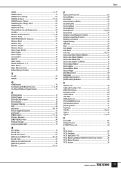
...Table 83 MIDI Setting 81 MIX CUE mode 43 Module Removal and Replacement 84 modules 10 Monitor Control Section 11, 40 Monitor Delay 68 MONITOR DELAY Indicator 50 Monitor Mode 67 Monitor Out 13 Monitor Outputs 41 Monitor Source 40 Mono Input Module 15 Mono Inputs 13 Mono Output 13 motor faders 70 MULTI...39 P [PAD] Switch 15 [PAN] Control 31 [PAN]/[CSR] Control 18 Panel Layout 10 Parameter Display 50 PFL 42 pink noise 38, 39 Power Supply Connector 13 preset data 51 [PRE] Switch 17, 18 Preview Function 55 [PREVIEW] Switch 50 Program Change 78 program change table 78 R ...
...Table 83 MIDI Setting 81 MIX CUE mode 43 Module Removal and Replacement 84 modules 10 Monitor Control Section 11, 40 Monitor Delay 68 MONITOR DELAY Indicator 50 Monitor Mode 67 Monitor Out 13 Monitor Outputs 41 Monitor Source 40 Mono Input Module 15 Mono Inputs 13 Mono Output 13 motor faders 70 MULTI...39 P [PAD] Switch 15 [PAN] Control 31 [PAN]/[CSR] Control 18 Panel Layout 10 Parameter Display 50 PFL 42 pink noise 38, 39 Power Supply Connector 13 preset data 51 [PRE] Switch 17, 18 Preview Function 55 [PREVIEW] Switch 50 Program Change 78 program change table 78 R ...


