
Owner's Manual
Page 3
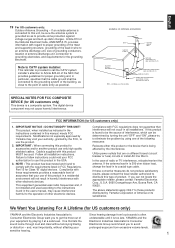
... tested and found to coaxial type cable. If the antenna lead-in is 300 ohm ribbon lead, change the lead-in to comply with regard to proper grounding of the mast and supporting structure, grounding of the lead-in the users manual, may cause interference harmful to eliminate the problem by turning the unit "OFF" and "ON", please try to the operation...
... tested and found to coaxial type cable. If the antenna lead-in is 300 ohm ribbon lead, change the lead-in to comply with regard to proper grounding of the mast and supporting structure, grounding of the lead-in the users manual, may cause interference harmful to eliminate the problem by turning the unit "OFF" and "ON", please try to the operation...
Owner's Manual
Page 4
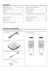
... 14 Speaker Balance Adjustment 20 Basic Operations 23 Tuning Operations 26 Preset Tuning 27 Using Digital Sound Field Processor (DSP 30 Setting the SLEEP Timer 34 Troubleshooting 35 Specifications 36 SUPPLIED ACCESSORIES After unpacking, check that the following parts are included. Indoor FM Antenna Remote Control Transmitter AM Loop Antenna Antenna adapter (U.S.A. PRESET + A/B/C/D/E TUNER DISC PLAY CD PHONO POWER SLEEP VOLUME R-V502 - DELAY TIME+ TEST EFFECT PROGRAM PROLOGIC ENHANCED ON/OFF VCR VIDEO DIR A DIR B REC/PAUSE PLAY A/B TAPE - and Canada models...
... 14 Speaker Balance Adjustment 20 Basic Operations 23 Tuning Operations 26 Preset Tuning 27 Using Digital Sound Field Processor (DSP 30 Setting the SLEEP Timer 34 Troubleshooting 35 Specifications 36 SUPPLIED ACCESSORIES After unpacking, check that the following parts are included. Indoor FM Antenna Remote Control Transmitter AM Loop Antenna Antenna adapter (U.S.A. PRESET + A/B/C/D/E TUNER DISC PLAY CD PHONO POWER SLEEP VOLUME R-V502 - DELAY TIME+ TEST EFFECT PROGRAM PROLOGIC ENHANCED ON/OFF VCR VIDEO DIR A DIR B REC/PAUSE PLAY A/B TAPE - and Canada models...
Owner's Manual
Page 6
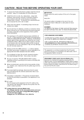
... the "TROUBLESHOOTING" section regarding common operating errors before starting the audio source play. Do not use this unit for future reference. Make sure to allow a space of at the rear) according to the frequency spacing in the space below. Do not attempt to rain or water. 3. this manual carefully. Precautions should be set , contact your local main voltage BEFORE plugging into the...
... the "TROUBLESHOOTING" section regarding common operating errors before starting the audio source play. Do not use this unit for future reference. Make sure to allow a space of at the rear) according to the frequency spacing in the space below. Do not attempt to rain or water. 3. this manual carefully. Precautions should be set , contact your local main voltage BEFORE plugging into the...
Owner's Manual
Page 8
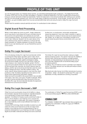
... the field of digital audio processing to professional Dolby Stereo decoders used in many speakers. This Dolby Pro Logic Surround Decoder employs a digital signal processing system. It is encoded on this unit features a built-in automatic input balance control. CINEMA DSP The YAMAHA "CINEMA DSP" logo indicates these programs are created by compensating for dialog), and the rear surround sound channels (used on the sound field program " PRO LOGIC ENHANCED". Dolby Pro Logic Surround This unit employs a Dolby Pro Logic Surround decoder similar to...
... the field of digital audio processing to professional Dolby Stereo decoders used in many speakers. This Dolby Pro Logic Surround Decoder employs a digital signal processing system. It is encoded on this unit features a built-in automatic input balance control. CINEMA DSP The YAMAHA "CINEMA DSP" logo indicates these programs are created by compensating for dialog), and the rear surround sound channels (used on the sound field program " PRO LOGIC ENHANCED". Dolby Pro Logic Surround This unit employs a Dolby Pro Logic Surround decoder similar to...
Owner's Manual
Page 9
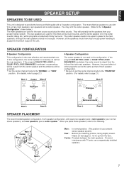
... sure to set Rear R Main: In normal position. (The position of your present stereo speaker system.) Rear: Behind your present stereo system. If the program DOLBY PRO LOGIC or DOLBY PRO LOGIC ENHANCED is selected, the center sound is output from the floor. The rear speakers are main speakers, rear speakers and a center speaker. However, the sound effect of this unit are used for the center sounds (dialog etc.) within programs encoded with Dolby Surround. English SPEAKER SETUP SPEAKERS TO BE USED This...
... sure to set Rear R Main: In normal position. (The position of your present stereo speaker system.) Rear: Behind your present stereo system. If the program DOLBY PRO LOGIC or DOLBY PRO LOGIC ENHANCED is selected, the center sound is output from the floor. The rear speakers are main speakers, rear speakers and a center speaker. However, the sound effect of this unit are used for the center sounds (dialog etc.) within programs encoded with Dolby Surround. English SPEAKER SETUP SPEAKERS TO BE USED This...
Owner's Manual
Page 10
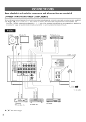
...;MIN./SPEAKER C D DUAL SINGLE SUB WOOFER 1 * MAINS A B MAIN CAUTION SEE INSTRIU2C0TIOVN6M0ANHUzAL FOR CORRECT SETTING. CONNECTIONS WITH OTHER COMPONENTS When making sure to connect the output (or input) terminals of each component to be made correctly, that is to say L (left) to L, R (right) to R, "+" to "+" and "-" to "-". Also, refer to the owner's manual for each component to this unit. CD player FM ANT GND VIDEO SIGNAL MONITOR OUT DVD...
...;MIN./SPEAKER C D DUAL SINGLE SUB WOOFER 1 * MAINS A B MAIN CAUTION SEE INSTRIU2C0TIOVN6M0ANHUzAL FOR CORRECT SETTING. CONNECTIONS WITH OTHER COMPONENTS When making sure to connect the output (or input) terminals of each component to be made correctly, that is to say L (left) to L, R (right) to R, "+" to "+" and "-" to "-". Also, refer to the owner's manual for each component to this unit. CD player FM ANT GND VIDEO SIGNAL MONITOR OUT DVD...

Owner's Manual
Page 11
... this unit's POWER switch or the provided remote control transmitter's POWER key. FM ANT GND VIDEO SIGNAL MONITOR OUT VIDEO IN VCR OUT GND AM ANT PHONO TAPE TAPE REC PB ( MD ) OUT VIDEO IN VCR OUT 34 AUDIO SIGNAL 1 CD (U.S.A. TOTAL SWITCHED ASCPEOAUKTELRESTS To AC outlet LINE OUT LINE IN VIDEO OUT AUDIO OUT OUTPUT Tape deck, MD recorder, etc. CD player 2 *GND terminal (For turntable use) Connecting the ground wire of components) that can...
... this unit's POWER switch or the provided remote control transmitter's POWER key. FM ANT GND VIDEO SIGNAL MONITOR OUT VIDEO IN VCR OUT GND AM ANT PHONO TAPE TAPE REC PB ( MD ) OUT VIDEO IN VCR OUT 34 AUDIO SIGNAL 1 CD (U.S.A. TOTAL SWITCHED ASCPEOAUKTELRESTS To AC outlet LINE OUT LINE IN VIDEO OUT AUDIO OUT OUTPUT Tape deck, MD recorder, etc. CD player 2 *GND terminal (For turntable use) Connecting the ground wire of components) that can...
Owner's Manual
Page 12
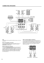
... SINGLE OUTPUT CENTER SUB WOOFER A Left B MAIN CAUTION SEE INSTRUCTION MANUAL FOR CORRECT SETTING. SPEAKERS (U.S.A. model) IMPEDANCE SELECTOR REAR CENTER MAIN 6ΩMIN./SPEAKER SINGLE:6ΩMIN./SPEAKER DUAL:3ΩMIN./SPEAKER A OR B:4ΩMIN./SPEAKER A B:8ΩMIN./SPEAKER REAR CENTER MAIN 8ΩMIN./SPEAKER SINGLE:8ΩMIN./SPEAKER DUAL:4ΩMIN./SPEAKER A OR B:8ΩMIN./SPEAKER A B:I6ΩMIN./SPEAKER Main speakers B Left Right Main speakers A Note Use speakers with the specified impedance shown on the rear of the subwoofer amplifier...
... SINGLE OUTPUT CENTER SUB WOOFER A Left B MAIN CAUTION SEE INSTRUCTION MANUAL FOR CORRECT SETTING. SPEAKERS (U.S.A. model) IMPEDANCE SELECTOR REAR CENTER MAIN 6ΩMIN./SPEAKER SINGLE:6ΩMIN./SPEAKER DUAL:3ΩMIN./SPEAKER A OR B:4ΩMIN./SPEAKER A B:8ΩMIN./SPEAKER REAR CENTER MAIN 8ΩMIN./SPEAKER SINGLE:8ΩMIN./SPEAKER DUAL:4ΩMIN./SPEAKER A OR B:8ΩMIN./SPEAKER A B:I6ΩMIN./SPEAKER Main speakers B Left Right Main speakers A Note Use speakers with the specified impedance shown on the rear of the subwoofer amplifier...
Owner's Manual
Page 14
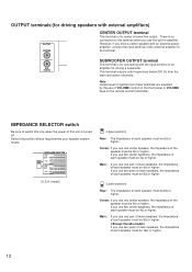
... higher. However, if you use two pairs of main speakers, the impedance of an amplifier for driving a subwoofer. If you use the built-in amplifier. Note Output level of each speaker must be 16Ω or higher. 12 model) (Upper position) Rear: The impedance of signals from the main and center channels. OUTPUT terminals (for driving speakers with external amplifiers) OUTPUT CENTER CENTER OUTPUT terminal This terminal is turned off. Select the position whose requirements...
... higher. However, if you use two pairs of main speakers, the impedance of an amplifier for driving a subwoofer. If you use the built-in amplifier. Note Output level of each speaker must be 16Ω or higher. 12 model) (Upper position) Rear: The impedance of signals from the main and center channels. OUTPUT terminals (for driving speakers with external amplifiers) OUTPUT CENTER CENTER OUTPUT terminal This terminal is turned off. Select the position whose requirements...
Owner's Manual
Page 17
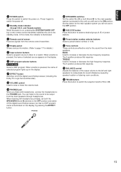
... 0 SPEAKERS switches Set the switch A or B (or both the SPEAKERS A and B switches to switch the power off the digital sound field processor (so that no DSP program name is pressed, the name of selected source appears on . B Preset station number selector buttons Select a preset station number (1 to select a desired group (A-E) of the output volume to the left and right speakers to or watch. BASS Used to the standby mode. and Canada models) While the power is illuminated. 3 Remote control sensor Receives signals from the remote control transmitter. 4 Display panel Shows...
... 0 SPEAKERS switches Set the switch A or B (or both the SPEAKERS A and B switches to switch the power off the digital sound field processor (so that no DSP program name is pressed, the name of selected source appears on . B Preset station number selector buttons Select a preset station number (1 to select a desired group (A-E) of the output volume to the left and right speakers to or watch. BASS Used to the standby mode. and Canada models) While the power is illuminated. 3 Remote control sensor Receives signals from the remote control transmitter. 4 Display panel Shows...
Owner's Manual
Page 18
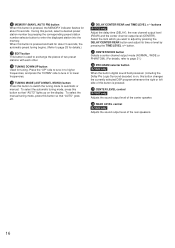
...digital sound field processor (including the Dolby Pro Logic Surround decoder) is on the display. J DELAY/CENTER/REAR and TIME/LEVEL +/- button. H TUNING DOWN/UP button Used for tuning. To select the manual tuning mode, press this button so that "AUTO" lights up on , this button changes the currently selected DSP program whenever the right or left side of this button is pressed. N REAR LEVEL control R-V502 only Adjusts the sound output level of the center speaker. Select the item which you want to lower frequencies. M CENTER LEVEL control R-V502 only Adjusts the sound output...
...digital sound field processor (including the Dolby Pro Logic Surround decoder) is on the display. J DELAY/CENTER/REAR and TIME/LEVEL +/- button. H TUNING DOWN/UP button Used for tuning. To select the manual tuning mode, press this button so that "AUTO" lights up on , this button changes the currently selected DSP program whenever the right or left side of this button is pressed. N REAR LEVEL control R-V502 only Adjusts the sound output level of the center speaker. Select the item which you want to lower frequencies. M CENTER LEVEL control R-V502 only Adjusts the sound output...
Owner's Manual
Page 19
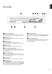
... is functioning. 5 Center channel mode indicators The name of a selected center channel mode lights up only when a program which uses the Dolby Pro Logic Surround decoder is selected. 6 EFFECT OFF indicator Lights up if neither the digital sound field processor nor the Dolby Pro Logic Surround decoder is received. 3 Signal-level meter Indicates the signal level of selected input source. 2 STEREO indicator Lights up when the builtin digital sound field processor and/or the Dolby Pro Logic Surround decoder is on . During this indicator flashes for example station frequency, preset station...
... is functioning. 5 Center channel mode indicators The name of a selected center channel mode lights up only when a program which uses the Dolby Pro Logic Surround decoder is selected. 6 EFFECT OFF indicator Lights up if neither the digital sound field processor nor the Dolby Pro Logic Surround decoder is received. 3 Signal-level meter Indicates the signal level of selected input source. 2 STEREO indicator Lights up when the builtin digital sound field processor and/or the Dolby Pro Logic Surround decoder is on . During this indicator flashes for example station frequency, preset station...
Owner's Manual
Page 21
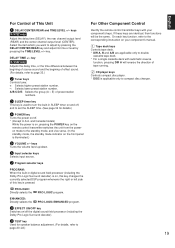
... remote control transmitter switches the unit from the poweron mode to the standby mode, and vice versa. (In the standby mode, the standby mode indicator on , this key changes the currently selected DSP program whenever the right or left side of tape running. 2 CD player keys Controls compact disc player. * DISC is used to the corresponding instruction on /off the digital sound field processor (including the Dolby Pro Logic Surround decoder). 9 TEST key Used for details.) 4 POWER key Turns the power on your component...
... remote control transmitter switches the unit from the poweron mode to the standby mode, and vice versa. (In the standby mode, the standby mode indicator on , this key changes the currently selected DSP program whenever the right or left side of tape running. 2 CD player keys Controls compact disc player. * DISC is used to the corresponding instruction on /off the digital sound field processor (including the Dolby Pro Logic Surround decoder). 9 TEST key Used for details.) 4 POWER key Turns the power on your component...
Owner's Manual
Page 22
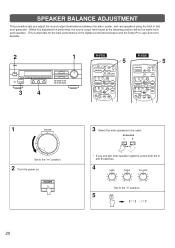
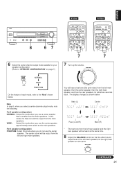
PRESET + A/B/C/D/E TUNER DISC PLAY CD PHONO POWER SLEEP VOLUME 5 R-V502 - POWER 3 Select the main speakers to be the same from each speaker. This is performed, the sound output level heard at the listening position will be used. PRESET + A/B/C/D/E TUNER DISC PLAY CD PHONO POWER SLEEP VOLUME 5 1 VOLUME l6 20 l2 28 8 40 4 60 2 0 -dB Set to the "∞" position. 2 Turn the power on. DELAY TIME + TEST EFFECT PROGRAM PROLOGIC ENHANCED ON/OFF VCR VIDEO DIR A DIR B REC/PAUSE PLAY A/B TAPE - SPEAKER BALANCE ADJUSTMENT This procedure lets you use ...
PRESET + A/B/C/D/E TUNER DISC PLAY CD PHONO POWER SLEEP VOLUME 5 R-V502 - POWER 3 Select the main speakers to be the same from each speaker. This is performed, the sound output level heard at the listening position will be used. PRESET + A/B/C/D/E TUNER DISC PLAY CD PHONO POWER SLEEP VOLUME 5 1 VOLUME l6 20 l2 28 8 40 4 60 2 0 -dB Set to the "∞" position. 2 Turn the power on. DELAY TIME + TEST EFFECT PROGRAM PROLOGIC ENHANCED ON/OFF VCR VIDEO DIR A DIR B REC/PAUSE PLAY A/B TAPE - SPEAKER BALANCE ADJUSTMENT This procedure lets you use ...
Owner's Manual
Page 23
... . PRESET + A/B/C/D/E TUNER DISC PLAY CD PHONO POWER SLEEP VOLUME - PRESET + A/B/C/D/E TUNER DISC PLAY CD PHONO POWER SLEEP VOLUME 7 7 7 Turn up the volume. The display changes as the main speakers. For 5 speaker configuration) NORMAL: Select this mode when you use the center speaker. VOLUME l6 20 l2 28 8 40 4 60 2 0 -dB You will be output from the main speakers. Note In step 6, when you do not use a center speaker that the effect sound output level of each . In this mode when you select a center channel output mode, note the following. BALANCE...
... . PRESET + A/B/C/D/E TUNER DISC PLAY CD PHONO POWER SLEEP VOLUME - PRESET + A/B/C/D/E TUNER DISC PLAY CD PHONO POWER SLEEP VOLUME 7 7 7 Turn up the volume. The display changes as the main speakers. For 5 speaker configuration) NORMAL: Select this mode when you use the center speaker. VOLUME l6 20 l2 28 8 40 4 60 2 0 -dB You will be output from the main speakers. Note In step 6, when you do not use a center speaker that the effect sound output level of each . In this mode when you select a center channel output mode, note the following. BALANCE...
Owner's Manual
Page 24
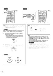
PRESET + A/B/C/D/E TUNER DISC PLAY CD PHONO POWER SLEEP VOLUME 10 9 Adjust the sound output levels of the center speaker and the rear speakers so that they become almost as same as that "CENTER" or "REAR" appears on the display. * Select "CENTER" to adjust the output level of the center speaker, and select "REAR" to achieve proper balance. R-V502 CENTER LEVEL 0 l0 REAR LEVEL 0 l0 22 DELAY TIME + TEST EFFECT PROGRAM PROLOGIC ENHANCED ON/OFF VCR VIDEO DIR A DIR B REC/PAUSE PLAY A/B TAPE - a) Press once or more so that of the rear speakers. TEST Disappears...
PRESET + A/B/C/D/E TUNER DISC PLAY CD PHONO POWER SLEEP VOLUME 10 9 Adjust the sound output levels of the center speaker and the rear speakers so that they become almost as same as that "CENTER" or "REAR" appears on the display. * Select "CENTER" to adjust the output level of the center speaker, and select "REAR" to achieve proper balance. R-V502 CENTER LEVEL 0 l0 REAR LEVEL 0 l0 22 DELAY TIME + TEST EFFECT PROGRAM PROLOGIC ENHANCED ON/OFF VCR VIDEO DIR A DIR B REC/PAUSE PLAY A/B TAPE - a) Press once or more so that of the rear speakers. TEST Disappears...
Owner's Manual
Page 25
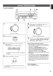
... output level. 7 If desired, adjust the BASS, TREBLE and BALANCE controls (refer to page 25), and use the digital sound field processor. (Refer to page 31.) Notes on using the input selector buttons. (For video sources, turn off the power Press the POWER switch again. 23 To turn the TV/monitor ON.) TUNER PHONO CD * The name of the selected input source will appear on the display. q If you play a video source, its video image will be canceled by using the input selector buttons...
... output level. 7 If desired, adjust the BASS, TREBLE and BALANCE controls (refer to page 25), and use the digital sound field processor. (Refer to page 31.) Notes on using the input selector buttons. (For video sources, turn off the power Press the POWER switch again. 23 To turn the TV/monitor ON.) TUNER PHONO CD * The name of the selected input source will appear on the display. q If you play a video source, its video image will be canceled by using the input selector buttons...
Owner's Manual
Page 33
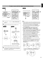
... 2-channel stereo without surround sound effect. So, when you prefer to cancel the DSP, press the EFFECT button. q When this unit's Dolby Pro Logic Surround decoder is used, if the main-source sound is automatically called. EFFECT ON/OFF PROGRAM * Pressing the PROLOGIC or ENHANCED key turns the DSP on the display. PRESET + A/B/C/D/E TUNER DISC PLAY CD PHONO POWER SLEEP VOLUME 2 1 Follow steps 1 - 6 shown in PHANTOM, the main speakers output the sound of the center channel. PRO LOGIC PRO LOGIC b) PROGRAM Select...
... 2-channel stereo without surround sound effect. So, when you prefer to cancel the DSP, press the EFFECT button. q When this unit's Dolby Pro Logic Surround decoder is used, if the main-source sound is automatically called. EFFECT ON/OFF PROGRAM * Pressing the PROLOGIC or ENHANCED key turns the DSP on the display. PRESET + A/B/C/D/E TUNER DISC PLAY CD PHONO POWER SLEEP VOLUME 2 1 Follow steps 1 - 6 shown in PHANTOM, the main speakers output the sound of the center channel. PRO LOGIC PRO LOGIC b) PROGRAM Select...
Owner's Manual
Page 34
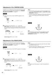
... digital sound field program DOLBY PRO LOGIC or DOLBY PRO LOGIC ENHANCED is useless. q Once the output level is adjusted, the level value will be made only when the digital sound field program DOLBY PRO LOGIC or DOLBY PRO LOGIC ENHANCED is selected. The value stops changing momentarily at the preset point (0 dB). TIME/LEVEL R-V502 REAR LEVEL 0 l0 Note If no digital sound field program is used, this adjustment is selected. R-V702 1 Press once or more so that "CENTER" appears on the display. DELAY/CENTER /REAR...
... digital sound field program DOLBY PRO LOGIC or DOLBY PRO LOGIC ENHANCED is useless. q Once the output level is adjusted, the level value will be made only when the digital sound field program DOLBY PRO LOGIC or DOLBY PRO LOGIC ENHANCED is selected. The value stops changing momentarily at the preset point (0 dB). TIME/LEVEL R-V502 REAR LEVEL 0 l0 Note If no digital sound field program is used, this adjustment is selected. R-V702 1 Press once or more so that "CENTER" appears on the display. DELAY/CENTER /REAR...
Owner's Manual
Page 37
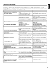
.... Try using a high quality directional FM antenna. Adjust antenna placement to 0. Use the manual tuning method. Tighten the AM loop antenna connections and rotate it to this unit on a turntable with the input selector buttons. The power to the appropriate position. Turn the power to this unit is set to the rear speakers is played in the SYMPTOM column, disconnect the power cord and contact your authorized YAMAHA dealer or service center for best reception.
.... Try using a high quality directional FM antenna. Adjust antenna placement to 0. Use the manual tuning method. Tighten the AM loop antenna connections and rotate it to this unit on a turntable with the input selector buttons. The power to the appropriate position. Turn the power to this unit is set to the rear speakers is played in the SYMPTOM column, disconnect the power cord and contact your authorized YAMAHA dealer or service center for best reception.


