
Owner's Manual
Page 1
... for selecting this YAMAHA stereo receiver. Serial No.: The serial number is intended to alert you to persons. WARNING TO REDUCE THE RISK OF FIRE OR ELECTRIC SHOCK, DO NOT EXPOSE THIS UNIT TO RAIN OR MOISTURE. Please record the serial number of This Unit 5 Speaker Setup for This Unit 6 Connections 7 Speaker Balance Adjustment ... 12 Basic Operations 15 Tuning Operations 18 Preset Tuning 19 Using Digital Sound Field Processor (DSP 22 Setting...
... for selecting this YAMAHA stereo receiver. Serial No.: The serial number is intended to alert you to persons. WARNING TO REDUCE THE RISK OF FIRE OR ELECTRIC SHOCK, DO NOT EXPOSE THIS UNIT TO RAIN OR MOISTURE. Please record the serial number of This Unit 5 Speaker Setup for This Unit 6 Connections 7 Speaker Balance Adjustment ... 12 Basic Operations 15 Tuning Operations 18 Preset Tuning 19 Using Digital Sound Field Processor (DSP 22 Setting...
Owner's Manual
Page 2
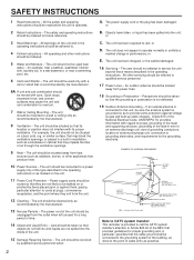
... routed so that produce heat. 10 Power Sources - All warnings on or pinched by the manufacturer. 13 Nonuse Periods - Quick stops, excessive force, and uneven surfaces may impede the flow of the unit. 15 Damage Requiring Service - The power-supply cord or the plug has been damaged; or E. NATIONAL ELECTRICAL CODE ANTENNA LEAD IN WIRE ANTENNA DISCHARGE UNIT (NEC SECTION 810...
... routed so that produce heat. 10 Power Sources - All warnings on or pinched by the manufacturer. 13 Nonuse Periods - Quick stops, excessive force, and uneven surfaces may impede the flow of the unit. 15 Damage Requiring Service - The power-supply cord or the plug has been damaged; or E. NATIONAL ELECTRICAL CODE ANTENNA LEAD IN WIRE ANTENNA DISCHARGE UNIT (NEC SECTION 810...

Owner's Manual
Page 3
... finest performance, please read the "TROUBLESHOOTING" section regarding common operating errors before starting the audio source play back has been started. 8 To prevent lightning damage, pull out the power cord and remove the antenna cable during an electrical storm. 9 Be sure to read this might damage the finish. This product, when installed as indicated in the instructions contained in this product in...
... finest performance, please read the "TROUBLESHOOTING" section regarding common operating errors before starting the audio source play back has been started. 8 To prevent lightning damage, pull out the power cord and remove the antenna cable during an electrical storm. 9 Be sure to read this might damage the finish. This product, when installed as indicated in the instructions contained in this product in...

Owner's Manual
Page 4
...+ 20W (8Ω) RMS Output Power, 0.3% THD, 1 kHz q Digital Sound Field Processor 6 Programs for Digital Sound Field Processing 2 Programs for Dolby Surround Decoding (DOLBY PRO LOGIC and DOLBY PRO LOGIC ENHANCED) q Automatic Input Balance Control for Dolby Surround q Test Tone Generator for Easier Speaker Output Balance Adjustment q 3 Center Channel Modes (NORMAL/WIDE/PHANTOM) q 40-Station Random Access Preset Tuning q Automatic Preset Tuning q Preset Station Shifting Capability (Preset Editing) q IF Count Direct PLL Synthesizer Tuning System q Video Signal Input/Output Capability q SLEEP...
...+ 20W (8Ω) RMS Output Power, 0.3% THD, 1 kHz q Digital Sound Field Processor 6 Programs for Digital Sound Field Processing 2 Programs for Dolby Surround Decoding (DOLBY PRO LOGIC and DOLBY PRO LOGIC ENHANCED) q Automatic Input Balance Control for Dolby Surround q Test Tone Generator for Easier Speaker Output Balance Adjustment q 3 Center Channel Modes (NORMAL/WIDE/PHANTOM) q 40-Station Random Access Preset Tuning q Automatic Preset Tuning q Preset Station Shifting Capability (Preset Editing) q IF Count Direct PLL Synthesizer Tuning System q Video Signal Input/Output Capability q SLEEP...

Owner's Manual
Page 5
... video sources using the built-in effect only three channels: left, right, and rear. This Dolby Pro Logic Surround Decoder employs a digital signal processing system. In addition, this unit takes full advantage of Yamaha's undisputed leadership in less sophisticated home audio/video equipment. Please read this same sound in your own listening room, so you'll feel all in a safe place for Yamaha engineers to conventional analog Dolby signal...
... video sources using the built-in effect only three channels: left, right, and rear. This Dolby Pro Logic Surround Decoder employs a digital signal processing system. In addition, this unit takes full advantage of Yamaha's undisputed leadership in less sophisticated home audio/video equipment. Please read this same sound in your own listening room, so you'll feel all in a safe place for Yamaha engineers to conventional analog Dolby signal...
Owner's Manual
Page 6
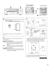
... right front speakers. The rear speakers are used for the center sound (dialog etc.) encoded with this configuration, the center speaker is necessary as well as that of other programs can be mainly front speakers, rear speakers, and a center speaker. (You can omit the center speaker. However, all the speakers should have high enough power handling to page 13.) 4-Speaker Configuration The center speaker is not used with the Dolby Surround. q Set the center channel mode to the...
... right front speakers. The rear speakers are used for the center sound (dialog etc.) encoded with this configuration, the center speaker is necessary as well as that of other programs can be mainly front speakers, rear speakers, and a center speaker. (You can omit the center speaker. However, all the speakers should have high enough power handling to page 13.) 4-Speaker Configuration The center speaker is not used with the Dolby Surround. q Set the center channel mode to the...
Owner's Manual
Page 8
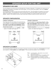
...;MIN./SPEAKER SPEAKERS SPEAKERS A B FRONT OUTPUT FRONT CENTER REAR LOW PASS fc:200Hz A B Right Left Right Left Front speakers A Front speakers B Note on both sides of each speaker is turned off. Select the position proper for the use two center speakers and place them on front speaker connection: One or two speaker systems can decrease the output level at the center position. Center speaker Center speaker 8 l l0 dB 0 dB FRONT LEVEL CONNECTING SPEAKERS Connect the respective speakers to this switch to...
...;MIN./SPEAKER SPEAKERS SPEAKERS A B FRONT OUTPUT FRONT CENTER REAR LOW PASS fc:200Hz A B Right Left Right Left Front speakers A Front speakers B Note on both sides of each speaker is turned off. Select the position proper for the use two center speakers and place them on front speaker connection: One or two speaker systems can decrease the output level at the center position. Center speaker Center speaker 8 l l0 dB 0 dB FRONT LEVEL CONNECTING SPEAKERS Connect the respective speakers to this switch to...

Owner's Manual
Page 10
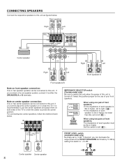
... model 1 SWITCHED OUTLET Use these to connect the power cords from the front and center channels are output. These outlets will normally minimize hum, but in some subwoofers, including the Yamaha Active Servo Processing Subwoofer System, the amplifier and subwoofer are for output to these terminals when you drive a center speaker with the ground wire disconnected. There is turned on. However, if you drive rear speakers with an external stereo power amplifier, connect the input terminals...
... model 1 SWITCHED OUTLET Use these to connect the power cords from the front and center channels are output. These outlets will normally minimize hum, but in some subwoofers, including the Yamaha Active Servo Processing Subwoofer System, the amplifier and subwoofer are for output to these terminals when you drive a center speaker with the ground wire disconnected. There is turned on. However, if you drive rear speakers with an external stereo power amplifier, connect the input terminals...

Owner's Manual
Page 12
... 2 SURROUND STADIUM DISCO 5 6 CONCERT VIDEO 3 ROCK 7 MONO MOVIE 4 HALL 8 VCR 2 V-AUX DSP EFFECT ON/OFF MASTER VOLUME REC PAUSE DIR A PLAY DIR B TAPE MON TEST STOP LD/TV PRO LOGIC ENHANCED CNCT VIDEO VCR 1 CENTER SUR. Otherwise, the result may not be used. SPEAKERS A B ON ON OFF OFF * If you adjust the sound output level balance between the front, center, and rear speakers using the built-in test tone generator. The adjustment of the digital sound field processor. SPEAKER BALANCE ADJUSTMENT...
... 2 SURROUND STADIUM DISCO 5 6 CONCERT VIDEO 3 ROCK 7 MONO MOVIE 4 HALL 8 VCR 2 V-AUX DSP EFFECT ON/OFF MASTER VOLUME REC PAUSE DIR A PLAY DIR B TAPE MON TEST STOP LD/TV PRO LOGIC ENHANCED CNCT VIDEO VCR 1 CENTER SUR. Otherwise, the result may not be used. SPEAKERS A B ON ON OFF OFF * If you adjust the sound output level balance between the front, center, and rear speakers using the built-in test tone generator. The adjustment of the digital sound field processor. SPEAKER BALANCE ADJUSTMENT...
Owner's Manual
Page 13
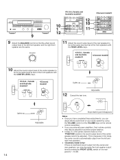
... use the center speaker approximately same sized as shown below . 6 8 Australia models SURROUND STADIUM DISCO 5 6 DSP ROCK 7 HALL 8 V-AUX EFFECT ON/OFF MASTER VOLUME CENTER LEVEL REAR LEVEL DELAY TIME TEST RESET CLEAR 7 8 7 8 REC PAUSE DIR A PLAY DIR B TAPE MON TEST STOP LD/TV PRO LOGIC ENHANCED CNCT VIDEO VCR 1 CENTER SUR. LEVEL MONO MOVIE STADIUM DISCO VCR 2 ROCK HALL EFFECT ON/OFF V AUX REAR LEVEL DELAY TIME VOLUME 6 Select the center channel output mode according to the "Note" shown below . The display changes as the front speakers...
... use the center speaker approximately same sized as shown below . 6 8 Australia models SURROUND STADIUM DISCO 5 6 DSP ROCK 7 HALL 8 V-AUX EFFECT ON/OFF MASTER VOLUME CENTER LEVEL REAR LEVEL DELAY TIME TEST RESET CLEAR 7 8 7 8 REC PAUSE DIR A PLAY DIR B TAPE MON TEST STOP LD/TV PRO LOGIC ENHANCED CNCT VIDEO VCR 1 CENTER SUR. LEVEL MONO MOVIE STADIUM DISCO VCR 2 ROCK HALL EFFECT ON/OFF V AUX REAR LEVEL DELAY TIME VOLUME 6 Select the center channel output mode according to the "Note" shown below . The display changes as the front speakers...
Owner's Manual
Page 14
.../OFF MASTER VOLUME CENTER LEVEL REAR LEVEL DELAY TIME TEST RESET CLEAR 12 10 11 REC PAUSE DIR A PLAY DIR B TAPE MON TEST STOP LD/TV PRO LOGIC ENHANCED CNCT VIDEO VCR 1 CENTER SUR. CENTER 00 Adjustable 14 Stops flashing and disappears Notes q Once you have completed these adjustments, you use external power amplifiers, their volume controls may decrease the front speaker output level by using the VOLUME control (or the VOLUME keys on the rear panel to achieve proper balance. BALANCE 0 l l 2 2 3 3 4 L5 4 5R 11 Adjust the sound output level...
.../OFF MASTER VOLUME CENTER LEVEL REAR LEVEL DELAY TIME TEST RESET CLEAR 12 10 11 REC PAUSE DIR A PLAY DIR B TAPE MON TEST STOP LD/TV PRO LOGIC ENHANCED CNCT VIDEO VCR 1 CENTER SUR. CENTER 00 Adjustable 14 Stops flashing and disappears Notes q Once you have completed these adjustments, you use external power amplifiers, their volume controls may decrease the front speaker output level by using the VOLUME control (or the VOLUME keys on the rear panel to achieve proper balance. BALANCE 0 l l 2 2 3 3 4 L5 4 5R 11 Adjust the sound output level...
Owner's Manual
Page 15
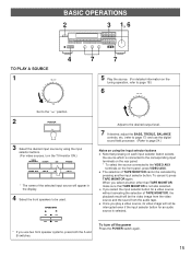
... speakers to the " ∞ " position. 2 POWER 3 Select the desired input source by pressing another input selector button. q Once you use the digital sound field processor. (Refer to page 24.) Notes on using the input selector buttons. (For video sources, turn off the power Press the POWER switch again. 15 To turn the TV/monitor ON.) TAPE MONITOR TUNER CD PHONO VIDEO AUX VCR 2 VCR 1 LD/TV * The name of TAPE MONITOR, the playback result will be used. BASIC OPERATIONS 2 3 1, 6 4 7 7 TO PLAY A SOURCE 1 5 Play the source...
... speakers to the " ∞ " position. 2 POWER 3 Select the desired input source by pressing another input selector button. q Once you use the digital sound field processor. (Refer to page 24.) Notes on using the input selector buttons. (For video sources, turn off the power Press the POWER switch again. 15 To turn the TV/monitor ON.) TAPE MONITOR TUNER CD PHONO VIDEO AUX VCR 2 VCR 1 LD/TV * The name of TAPE MONITOR, the playback result will be used. BASIC OPERATIONS 2 3 1, 6 4 7 7 TO PLAY A SOURCE 1 5 Play the source...

Owner's Manual
Page 17
... privately, set both at once. You can be output from the front speakers through headphones. TREBLE : Turn this clockwise to increase (or counterclockwise to decrease) the low frequency response. When you to select speaker system A or B, or both the SPEAKERS A and B switches to compensate for sound imbalance caused by pressing the EFFECT switch. SPEAKERS A B ON ON OFF OFF Adjusting the BALANCE control Adjust the balance of the output volume to the...
... privately, set both at once. You can be output from the front speakers through headphones. TREBLE : Turn this clockwise to increase (or counterclockwise to decrease) the low frequency response. When you to select speaker system A or B, or both the SPEAKERS A and B switches to compensate for sound imbalance caused by pressing the EFFECT switch. SPEAKERS A B ON ON OFF OFF Adjusting the BALANCE control Adjust the balance of the output volume to the...

Owner's Manual
Page 22
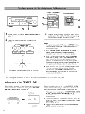
...CENTER LEVEL REAR LEVEL DELAY TIME TEST RESET CLEAR 7 6 4 7 POWER SLEEP DISC SKIP PHONO SKIP PAUSE/STOP PLAY CD DECK A/B PRESET A/B/C/D/E TUNER REC PAUSE DIR A PLAY DIR B TAPE MON TEST STOP LD/TV PRO LOGIC ENHANCED CNCT VIDEO VCR 1 CENTER SUR. You can create an excellent audio sound field by selecting the suitable program and adding desired adjustments. LEVEL MONO MOVIE STADIUM DISCO VCR 2 ROCK HALL EFFECT ON/OFF V AUX REAR LEVEL DELAY TIME VOLUME 5 6 3 1 Displays your selection on the DSP or other informations. 2 CENTER MODE Selects the center channel output mode...
...CENTER LEVEL REAR LEVEL DELAY TIME TEST RESET CLEAR 7 6 4 7 POWER SLEEP DISC SKIP PHONO SKIP PAUSE/STOP PLAY CD DECK A/B PRESET A/B/C/D/E TUNER REC PAUSE DIR A PLAY DIR B TAPE MON TEST STOP LD/TV PRO LOGIC ENHANCED CNCT VIDEO VCR 1 CENTER SUR. You can create an excellent audio sound field by selecting the suitable program and adding desired adjustments. LEVEL MONO MOVIE STADIUM DISCO VCR 2 ROCK HALL EFFECT ON/OFF V AUX REAR LEVEL DELAY TIME VOLUME 5 6 3 1 Displays your selection on the DSP or other informations. 2 CENTER MODE Selects the center channel output mode...
Owner's Manual
Page 24
... 1 PRO LOGIC 1 ENHANCED 2 SURROUND STADIUM DISCO 5 6 CONCERT VIDEO 3 ROCK 7 MONO MOVIE 4 HALL 8 VCR 2 V-AUX DSP EFFECT ON/OFF MASTER VOLUME CENTER LEVEL REAR LEVEL DELAY TIME TEST RESET CLEAR REC PAUSE DIR A PLAY DIR B TAPE MON TEST STOP LD/TV PRO LOGIC ENHANCED CNCT VIDEO VCR 1 CENTER SUR. The sound will be the normal 2-channel stereo without surround sound effect. However, the value stops changing momentarily at the preset point (80). Sound is selected, the CENTER LEVEL control cannot function. q Once the output level is adjusted, the level...
... 1 PRO LOGIC 1 ENHANCED 2 SURROUND STADIUM DISCO 5 6 CONCERT VIDEO 3 ROCK 7 MONO MOVIE 4 HALL 8 VCR 2 V-AUX DSP EFFECT ON/OFF MASTER VOLUME CENTER LEVEL REAR LEVEL DELAY TIME TEST RESET CLEAR REC PAUSE DIR A PLAY DIR B TAPE MON TEST STOP LD/TV PRO LOGIC ENHANCED CNCT VIDEO VCR 1 CENTER SUR. The sound will be the normal 2-channel stereo without surround sound effect. However, the value stops changing momentarily at the preset point (80). Sound is selected, the CENTER LEVEL control cannot function. q Once the output level is adjusted, the level...

Owner's Manual
Page 28
... MOVIE 4 HALL 8 VCR 2 V-AUX DSP EFFECT ON/OFF MASTER VOLUME CENTER LEVEL REAR LEVEL DELAY TIME TEST RESET CLEAR 7 8 1 2 POWER SLEEP DISC SKIP PHONO SKIP PAUSE/STOP PLAY CD DECK A/B PRESET A/B/C/D/E TUNER REC PAUSE DIR A PLAY DIR B TAPE MON TEST STOP LD/TV PRO LOGIC ENHANCED CNCT VIDEO VCR 1 CENTER SUR. If the CD player, tape deck, etc. LEVEL MONO MOVIE STADIUM DISCO VCR 2 ROCK HALL EFFECT ON/OFF V AUX REAR LEVEL DELAY TIME VOLUME 7 8 * When you operate this unit and/or other YAMAHA components with this unit...
... MOVIE 4 HALL 8 VCR 2 V-AUX DSP EFFECT ON/OFF MASTER VOLUME CENTER LEVEL REAR LEVEL DELAY TIME TEST RESET CLEAR 7 8 1 2 POWER SLEEP DISC SKIP PHONO SKIP PAUSE/STOP PLAY CD DECK A/B PRESET A/B/C/D/E TUNER REC PAUSE DIR A PLAY DIR B TAPE MON TEST STOP LD/TV PRO LOGIC ENHANCED CNCT VIDEO VCR 1 CENTER SUR. If the CD player, tape deck, etc. LEVEL MONO MOVIE STADIUM DISCO VCR 2 ROCK HALL EFFECT ON/OFF V AUX REAR LEVEL DELAY TIME VOLUME 7 8 * When you operate this unit and/or other YAMAHA components with this unit...

Owner's Manual
Page 29
..., their functions will reverse the direction of tape running. 3 LD player keys (U.S.A., Canada and Australia models only) Controls LD player. * Some models have a key which possesses both the functions of preset station buttons. 7 Input selector keys Selects input source. 8 (MASTER) VOLUME +/- For Control of This Unit 4 POWER Turns the power on/off. 5 SLEEP Refer to the corresponding instruction on page 26. 6 Tuner keys Controls tuner. +: Selects higher preset station number. -: Selects lower preset station number. For Other Component Control Identify the remote control transmitter keys...
..., their functions will reverse the direction of tape running. 3 LD player keys (U.S.A., Canada and Australia models only) Controls LD player. * Some models have a key which possesses both the functions of preset station buttons. 7 Input selector keys Selects input source. 8 (MASTER) VOLUME +/- For Control of This Unit 4 POWER Turns the power on/off. 5 SLEEP Refer to the corresponding instruction on page 26. 6 Tuner keys Controls tuner. +: Selects higher preset station number. -: Selects lower preset station number. For Other Component Control Identify the remote control transmitter keys...
Owner's Manual
Page 30
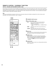
... PLAY PHONO CD DECK A/B PRESET A/B/C/D/E TUNER SEARCH STOP PLAY TAPE MON REC MUTE REC/PAUSE DIR A DIR B SEARCH PAUSE/STOP PLAY LD/TV CHAPTER/CH DISPLAY STOP VCR 1 PRO LOGIC 1 ENHANCED 2 SURROUND STADIUM DISCO 5 6 CONCERT VIDEO 3 ROCK 7 MONO MOVIE 4 HALL 8 VCR 2 V-AUX DSP EFFECT ON/OFF MASTER VOLUME CENTER LEVEL REAR LEVEL DELAY TIME TEST RESET CLEAR ˜ – TRANSMIT/LEARN indicator — YPC-USER-LEARN switch YPC: Set to this position when using preset key functions (for learning other remote control...
... PLAY PHONO CD DECK A/B PRESET A/B/C/D/E TUNER SEARCH STOP PLAY TAPE MON REC MUTE REC/PAUSE DIR A DIR B SEARCH PAUSE/STOP PLAY LD/TV CHAPTER/CH DISPLAY STOP VCR 1 PRO LOGIC 1 ENHANCED 2 SURROUND STADIUM DISCO 5 6 CONCERT VIDEO 3 ROCK 7 MONO MOVIE 4 HALL 8 VCR 2 V-AUX DSP EFFECT ON/OFF MASTER VOLUME CENTER LEVEL REAR LEVEL DELAY TIME TEST RESET CLEAR ˜ – TRANSMIT/LEARN indicator — YPC-USER-LEARN switch YPC: Set to this position when using preset key functions (for learning other remote control...

Owner's Manual
Page 33
.... Tighten the AM loop antenna connections and rotate it to turn on a turntable with Auto tuning. Direct sunlight or lighting (of an inverter type of the main unit. Turn the power to this remote control transmitter are continuous crackling and hissing noises. Appropriate input selector is selected. The monaural sound source is not listed in DOLBY PRO LOGIC or DOLBY PRO LOGIC ENHANCED mode. Adjust it for best reception. Make the GND...
.... Tighten the AM loop antenna connections and rotate it to turn on a turntable with Auto tuning. Direct sunlight or lighting (of an inverter type of the main unit. Turn the power to this remote control transmitter are continuous crackling and hissing noises. Appropriate input selector is selected. The monaural sound source is not listed in DOLBY PRO LOGIC or DOLBY PRO LOGIC ENHANCED mode. Adjust it for best reception. Make the GND...
Owner's Manual
Page 34
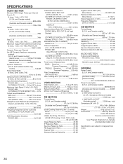
... or more Monitor Out Frequency Response 5 Hz to -Noise Ratio 50 dB Image Response Ratio 40 dB Spurious Response Ratio 50 dB Harmonic Distortion (400 Hz 0.3% AUDIO SECTION Output Level/Impedance FM (100% mod., 1 kHz 500 mV/2.2 k-ohms AM (30% mod., 400 Hz 150 mV/2.2 k-ohms GENERAL Power Supply [U.S.A. total 1 SWITCHED OUTLET [Australia model 120W max. SPECIFICATIONS AUDIO SECTION Minimum RMS Output Power per Channel (by...
... or more Monitor Out Frequency Response 5 Hz to -Noise Ratio 50 dB Image Response Ratio 40 dB Spurious Response Ratio 50 dB Harmonic Distortion (400 Hz 0.3% AUDIO SECTION Output Level/Impedance FM (100% mod., 1 kHz 500 mV/2.2 k-ohms AM (30% mod., 400 Hz 150 mV/2.2 k-ohms GENERAL Power Supply [U.S.A. total 1 SWITCHED OUTLET [Australia model 120W max. SPECIFICATIONS AUDIO SECTION Minimum RMS Output Power per Channel (by...


