
Owner's Manual
Page 1
... rear of this YAMAHA stereo receiver. OWNER'S MANUAL CONTENTS Safety Instructions 2 Supplied Accessories 4 Connections 5 Operations 9 Tuning Operations 12 Preset Tuning 13 Remote Control Transmitter ...16 Notes about the Remote Control Transmitter 17 Troubleshooting 18 Specifications 19 IMPORTANT! WARNING TO REDUCE THE RISK OF FIRE OR ELECTRIC SHOCK, DO NOT EXPOSE THIS UNIT TO RAIN OR MOISTURE. Model: Serial No.: The serial number is intended to alert you for future reference. RX-485/385 Natural Sound Stereo Receiver...
... rear of this YAMAHA stereo receiver. OWNER'S MANUAL CONTENTS Safety Instructions 2 Supplied Accessories 4 Connections 5 Operations 9 Tuning Operations 12 Preset Tuning 13 Remote Control Transmitter ...16 Notes about the Remote Control Transmitter 17 Troubleshooting 18 Specifications 19 IMPORTANT! WARNING TO REDUCE THE RISK OF FIRE OR ELECTRIC SHOCK, DO NOT EXPOSE THIS UNIT TO RAIN OR MOISTURE. Model: Serial No.: The serial number is intended to alert you for future reference. RX-485/385 Natural Sound Stereo Receiver...
Owner's Manual
Page 2
... uneven surfaces may impede the flow of the National Electrical Code, ANSI/NFPA 70, provides information with care. The power-supply cord or the plug has been damaged; or B. The unit does not appear to overturn. 7 Wall or Ceiling Mounting - All other instructions should be followed. 5 Water and Moisture - PART H) Note to CATV system installer (U.S.A.): This reminder is...
... uneven surfaces may impede the flow of the National Electrical Code, ANSI/NFPA 70, provides information with care. The power-supply cord or the plug has been damaged; or B. The unit does not appear to overturn. 7 Wall or Ceiling Mounting - All other instructions should be followed. 5 Water and Moisture - PART H) Note to CATV system installer (U.S.A.): This reminder is...
Owner's Manual
Page 3
... "TROUBLESHOOTING" section regarding common operating errors before starting the audio source play. Never pull the wires themselves. 5 The openings on the rear panel if that equipment requires more power than the outlet is often undetectable until it at a safe level. Increase the volume gradually to an appropriate level after playback has been started. 7 Do not attempt to accessories and/or another product use only...
... "TROUBLESHOOTING" section regarding common operating errors before starting the audio source play. Never pull the wires themselves. 5 The openings on the rear panel if that equipment requires more power than the outlet is often undetectable until it at a safe level. Increase the volume gradually to an appropriate level after playback has been started. 7 Do not attempt to accessories and/or another product use only...
Owner's Manual
Page 4
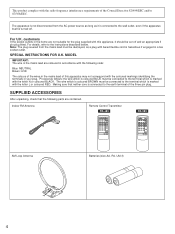
... that neither core is connected to the instructions described below. For details, refer to the earth terminal of the Council Directive 82/499/EEC and/or 87/308/EEC. This product complies with bared flexible cord is hazardous if engaged in a live socket outlet. Indoor FM Antenna Remote Control Transmitter RX-485 RX-385 AM Loop Antenna Batteries (size AA, R6...
... that neither core is connected to the instructions described below. For details, refer to the earth terminal of the Council Directive 82/499/EEC and/or 87/308/EEC. This product complies with bared flexible cord is hazardous if engaged in a live socket outlet. Indoor FM Antenna Remote Control Transmitter RX-485 RX-385 AM Loop Antenna Batteries (size AA, R6...
Owner's Manual
Page 5
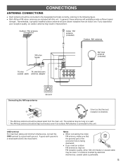
Outdoor FM antenna Indoor FM antenna (included) Outdoor AM antenna 300-ohm feeder 75-ohm 75-ohm/300-ohm coaxial cable antenna adapter FM 75Ω ANT UNBAL GND AM ANT PHONO CD AUX TAPE PB AM loop antenna (included) Ground Connecting the AM loop antenna Œ Ž Orient so that the grooved part of the connector hole is connected to the following figure. A good earth ground is preferable...
Outdoor FM antenna Indoor FM antenna (included) Outdoor AM antenna 300-ohm feeder 75-ohm 75-ohm/300-ohm coaxial cable antenna adapter FM 75Ω ANT UNBAL GND AM ANT PHONO CD AUX TAPE PB AM loop antenna (included) Ground Connecting the AM loop antenna Œ Ž Orient so that the grooved part of the connector hole is connected to the following figure. A good earth ground is preferable...
Owner's Manual
Page 6
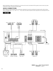
... to the owner's manual for each component to be sure all connections are being made correctly, that is to say L (left) to L, R (right) to R, "+" to "+" and "-" to "-". RX-485 Video cassette player etc. AUDIO CONNECTIONS When making connections between this unit. model) AC OUTLETS SWITCHED 120V 50Hz 100W MAX TOTAL To AC outlet GND OUTPUT OUTPUT LINE OUT LINE IN Turntable Compact disc player Tape deck 1 Right Left Speakers B * : Refer to...
... to the owner's manual for each component to be sure all connections are being made correctly, that is to say L (left) to L, R (right) to R, "+" to "+" and "-" to "-". RX-485 Video cassette player etc. AUDIO CONNECTIONS When making connections between this unit. model) AC OUTLETS SWITCHED 120V 50Hz 100W MAX TOTAL To AC outlet GND OUTPUT OUTPUT LINE OUT LINE IN Turntable Compact disc player Tape deck 1 Right Left Speakers B * : Refer to...
Owner's Manual
Page 7
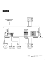
AUDIO OUT FM 75Ω ANT UNBAL GND AM ANT GND L PHONO CD AUX R TAPE 1 TAPE REC PB OUT Speakers A Right Left (U.S.A. model) SPEAKERS R L A A B B AC OUTLETS SWITCHED 120V 50Hz 100W MAX TOTAL To AC outlet Turntable Compact disc player Tape deck Right Left Speakers B GND OUTPUT OUTPUT LINE OUT LINE IN * : Refer to "ABOUT THE ACCESSORY TERMINALS" on page 8. 7 RX-385 Video cassette player etc.
AUDIO OUT FM 75Ω ANT UNBAL GND AM ANT GND L PHONO CD AUX R TAPE 1 TAPE REC PB OUT Speakers A Right Left (U.S.A. model) SPEAKERS R L A A B B AC OUTLETS SWITCHED 120V 50Hz 100W MAX TOTAL To AC outlet Turntable Compact disc player Tape deck Right Left Speakers B GND OUTPUT OUTPUT LINE OUT LINE IN * : Refer to "ABOUT THE ACCESSORY TERMINALS" on page 8. 7 RX-385 Video cassette player etc.
Owner's Manual
Page 8
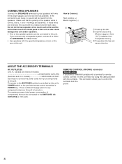
... components) that is 100 watts. If the connections are faulty, no sound will be heard from the provid 8 q Use speakers with the specified impedance shown on . The power to the SWITCHED outlets is turned on the rear of this unit. This connection allows you have a YAMAHA turntable with a terminal for remote control, connect it to either the SPEAKERS A or B terminals. Make sure that the polarity of the speaker wires...
... components) that is 100 watts. If the connections are faulty, no sound will be heard from the provid 8 q Use speakers with the specified impedance shown on . The power to the SWITCHED outlets is turned on the rear of this unit. This connection allows you have a YAMAHA turntable with a terminal for remote control, connect it to either the SPEAKERS A or B terminals. Make sure that the polarity of the speaker wires...
Owner's Manual
Page 9
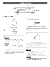
... selected input source will be used. RX-385 only q If both the A and B switches. 5 Play the source. (For detailed information on the rear panel. dB Adjust to the desired output level. 7 If desired, adjust the BASS, TREBLE, BALANCE and LOUDNESS controls, etc. (Refer to the " " position. 2 POWER 3 Select a desired input source. SPEAKERS A B ON ON OFF OFF * If you select TAPE 1 and TAPE 2 at the same time, the result will appear in the display. * Note that TAPE 1 and/or TAPE 2 are selected, TAPE MONITOR...
... selected input source will be used. RX-385 only q If both the A and B switches. 5 Play the source. (For detailed information on the rear panel. dB Adjust to the desired output level. 7 If desired, adjust the BASS, TREBLE, BALANCE and LOUDNESS controls, etc. (Refer to the " " position. 2 POWER 3 Select a desired input source. SPEAKERS A B ON ON OFF OFF * If you select TAPE 1 and TAPE 2 at the same time, the result will appear in the display. * Note that TAPE 1 and/or TAPE 2 are selected, TAPE MONITOR...
Owner's Manual
Page 10
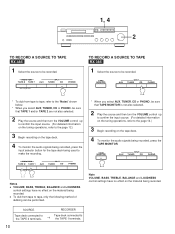
... TAPE RX-485 1 Select the source to be sure that TAPE 1 and/or TAPE 2 are not also selected. 2 Play the source and then turn the VOLUME control up to confirm the input source. (For detailed information on the tuning operations, refer to the page 12.) 3 Begin recording on the tape deck. 4 To monitor the audio signals being recorded, press the input selector button for the tape deck being used to make the recording. * When you select AUX, TUNER, CD or PHONO...
... TAPE RX-485 1 Select the source to be sure that TAPE 1 and/or TAPE 2 are not also selected. 2 Play the source and then turn the VOLUME control up to confirm the input source. (For detailed information on the tuning operations, refer to the page 12.) 3 Begin recording on the tape deck. 4 To monitor the audio signals being recorded, press the input selector button for the tape deck being used to make the recording. * When you select AUX, TUNER, CD or PHONO...
Owner's Manual
Page 11
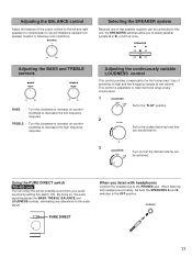
... the audio signal. I0 Using the PURE DIRECT switch RX-485 only You can FLAT - 30dB be connected to this clockwise to increase (or counterclockwise to retain full tonal range at once. BALANCE 0 L5 5R Adjusting the BASS and TREBLE controls BASS DEFEAT TREBLE DEFEAT -5 5+ -5 5+ BASS : Turn this switch ON. SPEAKERS A B ON ON OFF OFF Adjusting the continuously variable LOUDNESS control This control provides compensation for the human ears' loss of the output volume to...
... the audio signal. I0 Using the PURE DIRECT switch RX-485 only You can FLAT - 30dB be connected to this clockwise to increase (or counterclockwise to retain full tonal range at once. BALANCE 0 L5 5R Adjusting the BASS and TREBLE controls BASS DEFEAT TREBLE DEFEAT -5 5+ -5 5+ BASS : Turn this switch ON. SPEAKERS A B ON ON OFF OFF Adjusting the continuously variable LOUDNESS control This control provides compensation for the human ears' loss of the output volume to...
Owner's Manual
Page 12
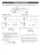
... frequency of the received station. Illuminates when an FM stereo broadcast is received in stereo. Ž Indicates the signal level of the received station. 12 Display information Œ STEREO Ž FM MHz 0 20 40 60 l00 * To continue tuning search, press and hold the button. However, if signals of the station you want to select are weak), change to the MANUAL TUNING method. DOWN TUNING UP To tune to a desired station manually. TUNING OPERATIONS...
... frequency of the received station. Illuminates when an FM stereo broadcast is received in stereo. Ž Indicates the signal level of the received station. 12 Display information Œ STEREO Ž FM MHz 0 20 40 60 l00 * To continue tuning search, press and hold the button. However, if signals of the station you want to select are weak), change to the MANUAL TUNING method. DOWN TUNING UP To tune to a desired station manually. TUNING OPERATIONS...
Owner's Manual
Page 13
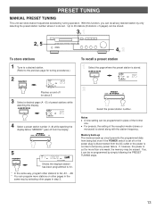
... for tuning procedures.) 2 MEMORY MAN'L/AUTO FM PRESET FM MEMORY Flashes on other pages in the same way by tuning operation. Memory back-up The memory back-up circuit prevents the programmed data from being lost even if the POWER switch is set off from the AC outlet or the power is stored along with the station frequency. A/B/C/D/E PRESET FM MEMORY 2 PRESET DOWN STATIONS UP Select the preset station number.
... for tuning procedures.) 2 MEMORY MAN'L/AUTO FM PRESET FM MEMORY Flashes on other pages in the same way by tuning operation. Memory back-up The memory back-up circuit prevents the programmed data from being lost even if the POWER switch is set off from the AC outlet or the power is stored along with the station frequency. A/B/C/D/E PRESET FM MEMORY 2 PRESET DOWN STATIONS UP Select the preset station number.
Owner's Manual
Page 14
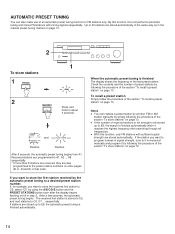
... monaural manually and program it reaches the highest frequency after the display begins flashing on/off in the manual preset tuning method on page 13. Flashes. After 5 seconds, the automatic preset tuning begins from A1. To recall a preset station Simply follow the procedure of the section "To recall a preset station" on page 13. If the station you want to store the first station received by using the A/B/C/D/E button and the PRESET STATIONS button...
... monaural manually and program it reaches the highest frequency after the display begins flashing on/off in the manual preset tuning method on page 13. Flashes. After 5 seconds, the automatic preset tuning begins from A1. To recall a preset station Simply follow the procedure of the section "To recall a preset station" on page 13. If the station you want to store the first station received by using the A/B/C/D/E button and the PRESET STATIONS button...
Owner's Manual
Page 15
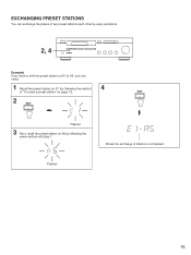
EXCHANGING PRESET STATIONS You can exchange the places of two preset stations each other by easy operations. 2, 4 Example) If you want to shift the preset station on E1 to A5, and vice versa. 1 Recall the preset station on E1 (by following the method 4 of stations is completed. 15 EDIT 2 EDIT Flashes 3 Next, recall the preset station on page 13). Flashes Shows the exchange of "To recall a preset station" on A5 by following the same method with step 1.
EXCHANGING PRESET STATIONS You can exchange the places of two preset stations each other by easy operations. 2, 4 Example) If you want to shift the preset station on E1 to A5, and vice versa. 1 Recall the preset station on E1 (by following the method 4 of stations is completed. 15 EDIT 2 EDIT Flashes 3 Next, recall the preset station on page 13). Flashes Shows the exchange of "To recall a preset station" on A5 by following the same method with step 1.
Owner's Manual
Page 16
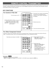
... This Unit Turns the power on/off one hour after this remote control transmitter will also control various functions of each key function, refer to compact disc changer. If the CD player, turntable and tape deck connected to this unit are applicable only to control all the most commonly used functions of tape running. Selects input source. If these keys are replaced by TAPE only. 16 Controls tape deck. * DIR A, B and DECK A/B are YAMAHA components, then this key...
... This Unit Turns the power on/off one hour after this remote control transmitter will also control various functions of each key function, refer to compact disc changer. If the CD player, turntable and tape deck connected to this unit are applicable only to control all the most commonly used functions of tape running. Selects input source. If these keys are replaced by TAPE only. 16 Controls tape deck. * DIR A, B and DECK A/B are YAMAHA components, then this key...
Owner's Manual
Page 17
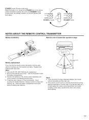
... to avoid direct lighting. 17 Replace both batteries with clothing, etc. Avoid touching the leaked material or letting it might cause the remote control transmitter not to the main unit, the batteries are weak. q If the remote control sensor is half illuminated.) POWER on mode STANDBY mode NOTES ABOUT THE REMOTE CONTROL TRANSMITTER Battery installation Remote control transmitter operation range 2 1 3 Remote control sensor Battery replacement If you find that the remote control transmitter...
... to avoid direct lighting. 17 Replace both batteries with clothing, etc. Avoid touching the leaked material or letting it might cause the remote control transmitter not to the main unit, the batteries are weak. q If the remote control sensor is half illuminated.) POWER on mode STANDBY mode NOTES ABOUT THE REMOTE CONTROL TRANSMITTER Battery installation Remote control transmitter operation range 2 1 3 Remote control sensor Battery replacement If you find that the remote control transmitter...
Owner's Manual
Page 18
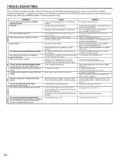
.... Connect the cord properly. Turn the power to the input source. Use high quality directional FM antenna. Use an outdoor antenna and a ground wire. Direct sunlight or lighting (of an inverter type of flourescent lamp etc.) is poor. The power to the receiver through the MC head amplifier. Only one side speaker outputs the sound. There are too weak. The remote control transmitter does not work. Appropriate input selector button is too weak. The protection circuit...
.... Connect the cord properly. Turn the power to the input source. Use high quality directional FM antenna. Use an outdoor antenna and a ground wire. Direct sunlight or lighting (of an inverter type of flourescent lamp etc.) is poor. The power to the receiver through the MC head amplifier. Only one side speaker outputs the sound. There are too weak. The remote control transmitter does not work. Appropriate input selector button is too weak. The protection circuit...
Owner's Manual
Page 19
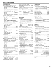
SPECIFICATIONS AUDIO SECTION Minimum RMS Output Power per Channel 8 ohms, 20 Hz to 20 kHz, 0.04% THD
SPECIFICATIONS AUDIO SECTION Minimum RMS Output Power per Channel 8 ohms, 20 Hz to 20 kHz, 0.04% THD


