

Owner's Manual
Page 1
NATURAL SOUND AV RECEIVER RX-V2092 CINEMA DSP 7ch POWER A/B/C/D/E 1 2 3 4 5 6 7 8 DIGITAL/ PRO LOGIC ENHANCED MOVIE THEATER TV SPORTS STADIUM DISCO ROCK CONCERT JAZZ CLUB CHURCH CONCERT HALL VCR 2 VCR 1 DVD/LD VIDEO AUX TAPE (MD) ...
NATURAL SOUND AV RECEIVER RX-V2092 CINEMA DSP 7ch POWER A/B/C/D/E 1 2 3 4 5 6 7 8 DIGITAL/ PRO LOGIC ENHANCED MOVIE THEATER TV SPORTS STADIUM DISCO ROCK CONCERT JAZZ CLUB CHURCH CONCERT HALL VCR 2 VCR 1 DVD/LD VIDEO AUX TAPE (MD) ...

Owner's Manual
Page 2
...installation, such as a bookcase or cabinet that objects do not fall into and liquids are not likely to qualified service personnel. 17 Power Lines - Care should be of sufficient magnitude to constitute a risk of important operating and maintenance (servicing) instructions in the operating instructions....recommended by the manufacturer. 13 Nonuse Periods - All warnings on a bed, sofa, rug, or similar surface, that produce heat. 10 Power Sources - The unit should be followed. 5 Water and Moisture - The unit should be adhered to cords at plugs, convenience receptacles, ...
...installation, such as a bookcase or cabinet that objects do not fall into and liquids are not likely to qualified service personnel. 17 Power Lines - Care should be of sufficient magnitude to constitute a risk of important operating and maintenance (servicing) instructions in the operating instructions....recommended by the manufacturer. 13 Nonuse Periods - All warnings on a bed, sofa, rug, or similar surface, that produce heat. 10 Power Sources - The unit should be followed. 5 Water and Moisture - The unit should be adhered to cords at plugs, convenience receptacles, ...

Owner's Manual
Page 3
... the users manual, may not cause harmful interference. FCC INFORMATION (for Class "B" digital devices. Modifications not expressly approved by Yamaha may void your authority, granted by the interference. If this type of other electronic devices. English an antenna discharge unit, ...NATIONAL ELECTRICAL CODE ANTENNA LEAD IN WIRE ANTENNA DISCHARGE UNIT (NEC SECTION 810-20) GROUNDING CONDUCTORS (NEC SECTION 810-21) GROUND CLAMPS POWER SERVICE GROUNDING ELECTRODE SYSTEM (NEC ART 250. IMPORTANT : When connecting this manual, meets FCC requirements. PART H) We Want You ...
... the users manual, may not cause harmful interference. FCC INFORMATION (for Class "B" digital devices. Modifications not expressly approved by Yamaha may void your authority, granted by the interference. If this type of other electronic devices. English an antenna discharge unit, ...NATIONAL ELECTRICAL CODE ANTENNA LEAD IN WIRE ANTENNA DISCHARGE UNIT (NEC SECTION 810-20) GROUNDING CONDUCTORS (NEC SECTION 810-21) GROUND CLAMPS POWER SERVICE GROUNDING ELECTRODE SYSTEM (NEC ART 250. IMPORTANT : When connecting this manual, meets FCC requirements. PART H) We Want You ...

Owner's Manual
Page 5
... FOR CANADIAN CUSTOMER THIS CLASS B DIGITAL APPARATUS MEETS ALL REQUIREMENTS OF THE CANADIAN INTERFERENCECAUSING EQUIPMENT REGULATIONS. IF THIS UNIT FAILS TO TURN ON WHEN THE POWER SWITCH IS PRESSED The IMPEDANCE SELECTOR switch may not only damage the unit, but also cause fire. 4. AVOID EXCESSIVE HEAT, HUMIDITY, DUST AND VIBRATION... personnel. USE THIS UNIT WITH THE CORRECT VOLTAGE The voltage to an appropriate level after playback has been started. 10. YAMAHA will not be the same as other type of the unit. Please record the model and serial number of the unit. Model: Serial No...
... FOR CANADIAN CUSTOMER THIS CLASS B DIGITAL APPARATUS MEETS ALL REQUIREMENTS OF THE CANADIAN INTERFERENCECAUSING EQUIPMENT REGULATIONS. IF THIS UNIT FAILS TO TURN ON WHEN THE POWER SWITCH IS PRESSED The IMPEDANCE SELECTOR switch may not only damage the unit, but also cause fire. 4. AVOID EXCESSIVE HEAT, HUMIDITY, DUST AND VIBRATION... personnel. USE THIS UNIT WITH THE CORRECT VOLTAGE The voltage to an appropriate level after playback has been started. 10. YAMAHA will not be the same as other type of the unit. Please record the model and serial number of the unit. Model: Serial No...

Owner's Manual
Page 14
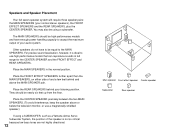
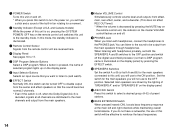
... use a sevenspeaker setup. Use of a Subwoofer Expands Your Sound Field It is also possible to choose the convenience of a Yamaha Active Servo Processing Subwoofer System, which has its own built-in power amplifier. 10 In the 4 or 5 speaker system, the Digital Sound Field Processing is effective not only for reinforcing bass frequencies...
... use a sevenspeaker setup. Use of a Subwoofer Expands Your Sound Field It is also possible to choose the convenience of a Yamaha Active Servo Processing Subwoofer System, which has its own built-in power amplifier. 10 In the 4 or 5 speaker system, the Digital Sound Field Processing is effective not only for reinforcing bass frequencies...
Owner's Manual
Page 16
... ideal to use a magnetically shielded speaker.) If using a subwoofer. Other speakers do not have enough power handling capacity to the MAIN SPEAKERS. They should be high performance models and have to be using a SUBWOOFER, such as a Yamaha Active Servo Subwoofer System, the position of and a few feet behind your listening position. Place...
... ideal to use a magnetically shielded speaker.) If using a subwoofer. Other speakers do not have enough power handling capacity to the MAIN SPEAKERS. They should be high performance models and have to be using a SUBWOOFER, such as a Yamaha Active Servo Subwoofer System, the position of and a few feet behind your listening position. Place...

Owner's Manual
Page 17
English CONTROLS & THEIR FUNCTIONS FRONT PANEL 1 23 4 5 67 8 NATURAL SOUND AV RECEIVER RX-V2092 CINEMA DSP 7ch POWER A/B/C/D/E 1 2 3 4 5 6 7 8 DIGITAL/ PRO LOGIC ENHANCED MOVIE THEATER TV SPORTS STADIUM DISCO ROCK CONCERT JAZZ CLUB CHURCH CONCERT HALL VCR 2 VCR 1 DVD/LD VIDEO AUX TAPE (MD) ...
English CONTROLS & THEIR FUNCTIONS FRONT PANEL 1 23 4 5 67 8 NATURAL SOUND AV RECEIVER RX-V2092 CINEMA DSP 7ch POWER A/B/C/D/E 1 2 3 4 5 6 7 8 DIGITAL/ PRO LOGIC ENHANCED MOVIE THEATER TV SPORTS STADIUM DISCO ROCK CONCERT JAZZ CLUB CHURCH CONCERT HALL VCR 2 VCR 1 DVD/LD VIDEO AUX TAPE (MD) ...
Owner's Manual
Page 18
... remote control unit are received here. 4 Display Panel See pages 16 to the ON position. A A/B/C/D/E Switch Press this switch to the OFF position. 1 POWER Switch Turns this unit on and off , when the Dolby Digital (AC-3) is decreased by the lighting of "SPEAKERS A" and/or "SPEAKERS B" on the... display panel. In this mode, the standby indicator is on, pressing the (SYSTEM POWER) OFF key on the remote control unit switches this unit to turn the power on, you will not use to select a desired group (A-E) of preset stations.
... remote control unit are received here. 4 Display Panel See pages 16 to the ON position. A A/B/C/D/E Switch Press this switch to the OFF position. 1 POWER Switch Turns this unit on and off , when the Dolby Digital (AC-3) is decreased by the lighting of "SPEAKERS A" and/or "SPEAKERS B" on the... display panel. In this mode, the standby indicator is on, pressing the (SYSTEM POWER) OFF key on the remote control unit switches this unit to turn the power on, you will not use to select a desired group (A-E) of preset stations.

Owner's Manual
Page 23
...RF output jack and no digital output jack for higher resolution and improved picture quality if your dealer if unsure of one or two external power amplifier(s) to drive the center speaker(s). 6 CENTER SPEAKERS Terminals When using the built-in center-channel amplifier, connect one or two center...Center-channel line outputs. Consult your VCR, monitor, etc. In place of the turntable to the line voltage in your area before applying power. To heighten safety and reduce interference, connect the GND terminal to the AM ANT and GND terminals. A GND Terminal Connects the ground ...
...RF output jack and no digital output jack for higher resolution and improved picture quality if your dealer if unsure of one or two external power amplifier(s) to drive the center speaker(s). 6 CENTER SPEAKERS Terminals When using the built-in center-channel amplifier, connect one or two center...Center-channel line outputs. Consult your VCR, monitor, etc. In place of the turntable to the line voltage in your area before applying power. To heighten safety and reduce interference, connect the GND terminal to the AM ANT and GND terminals. A GND Terminal Connects the ground ...

Owner's Manual
Page 24
...to "ON (5ch)" when setting up a full 7 or 6 speaker system, or to MAIN IN jacks when the built-in amplifier is made using an external power amplifier. The input source selection is used . Refer to PRE OUT jacks when the built-in amplifier is decoded are also output if they are... at the IN jack from the Room 2 remote control unit. H PRE OUT Jacks Main-channel line output. Connected to either of an external stereo power amplifier driving the front effect speakers. 20 J SUBWOOFER Jacks When using one subwoofer, connect its amplifier input to input jacks of external stereo...
...to "ON (5ch)" when setting up a full 7 or 6 speaker system, or to MAIN IN jacks when the built-in amplifier is made using an external power amplifier. The input source selection is used . Refer to PRE OUT jacks when the built-in amplifier is decoded are also output if they are... at the IN jack from the Room 2 remote control unit. H PRE OUT Jacks Main-channel line output. Connected to either of an external stereo power amplifier driving the front effect speakers. 20 J SUBWOOFER Jacks When using one subwoofer, connect its amplifier input to input jacks of external stereo...

Owner's Manual
Page 25
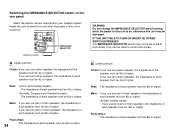
... to connect the MAIN IN jacks to this unit. "Switched" means that these sockets as long as their combined power consumption does not exceed the specified value shown. When using this unit's power switch. 21 N IMPEDANCE SELECTOR Switch Select the position whose requirements your speaker system meets. M MAIN SPEAKERS Terminals This unit...
... to connect the MAIN IN jacks to this unit. "Switched" means that these sockets as long as their combined power consumption does not exceed the specified value shown. When using this unit's power switch. 21 N IMPEDANCE SELECTOR Switch Select the position whose requirements your speaker system meets. M MAIN SPEAKERS Terminals This unit...

Owner's Manual
Page 29
... If, for 2-channel audio signals) of the LD player to this unit. In this case, switch off the power to the RF demodulator. GND 3 TAPE PB TAPE(MD) 4 REC OUT PCM/ DIGITAL IN (AC-3 DIGITAL IN...AC-3 RF OUT COAXIAL DIGITAL OUT AC-3 RF IN COAXIAL DIGITAL OUT OPTICAL DIGITAL OUT RF demodulator (YAMAHA APD-1 etc.) FREQUENCY STEP FM AM 50kHz 9kHz I00kHz I0kHz AUDIO SIGNAL PHONO 1 CD AUDIO SIGNAL... about switching the input mode. q When you want to play a CD also), there is the Yamaha model APD-1, you must switch off the RF demodulator to listen to CD sound surely. Notes on ...
... If, for 2-channel audio signals) of the LD player to this unit. In this case, switch off the power to the RF demodulator. GND 3 TAPE PB TAPE(MD) 4 REC OUT PCM/ DIGITAL IN (AC-3 DIGITAL IN...AC-3 RF OUT COAXIAL DIGITAL OUT AC-3 RF IN COAXIAL DIGITAL OUT OPTICAL DIGITAL OUT RF demodulator (YAMAHA APD-1 etc.) FREQUENCY STEP FM AM 50kHz 9kHz I00kHz I0kHz AUDIO SIGNAL PHONO 1 CD AUDIO SIGNAL... about switching the input mode. q When you want to play a CD also), there is the Yamaha model APD-1, you must switch off the RF demodulator to listen to CD sound surely. Notes on ...

Owner's Manual
Page 35
... the main speakers you use two sets of MAIN speakers, connect one set to the OFF position. If you will use an external power amplifier if more power is also possible to connect the left and right channels correctly. Connect the MAIN speakers to the ON position. Set the SPEAKERS switch... MAIN SPEAKERS TO THIS UNIT One or two sets of MAIN speakers can be connected to either the MAIN SPEAKERS A or B terminals. Main speaker A Power amplifier INPUT PRE OUT This unit Main speaker B Main speaker A Main speaker B 31 If you will not use only one set to the MAIN SPEAKERS...
... the main speakers you use two sets of MAIN speakers, connect one set to the OFF position. If you will use an external power amplifier if more power is also possible to connect the left and right channels correctly. Connect the MAIN speakers to the ON position. Set the SPEAKERS switch... MAIN SPEAKERS TO THIS UNIT One or two sets of MAIN speakers can be connected to either the MAIN SPEAKERS A or B terminals. Main speaker A Power amplifier INPUT PRE OUT This unit Main speaker B Main speaker A Main speaker B 31 If you will not use only one set to the MAIN SPEAKERS...

Owner's Manual
Page 36
... the C or D terminals and set the CENTER speaker switch so that it is released outward ("C OR D" position). Connect the REAR speakers to use an external power amp for any or all of the external amp. 32 Front effect speaker Center speaker Front effect speaker L Center speaker Center speaker R This unit L Rear...
... the C or D terminals and set the CENTER speaker switch so that it is released outward ("C OR D" position). Connect the REAR speakers to use an external power amp for any or all of the external amp. 32 Front effect speaker Center speaker Front effect speaker L Center speaker Center speaker R This unit L Rear...
Owner's Manual
Page 38
...:) If you use two center speakers, the impedance of each speaker must be 4Ω or higher. IF THIS UNIT FAILS TO TURN ON WHEN THE POWER SWITCH IS PRESSED The IMPEDANCE SELECTOR switch may be 8Ω or higher. Be sure to either end closely. (Lower position) Center: If you use...or higher. Rear: The impedance of each speaker must be 6Ω or higher. 34 WARNING Do not change the IMPEDANCE SELECTOR switch setting while the power to either end closely. If so, set to switch this unit is turned off. Main: If you use one pair of main speakers, the impedance...
...:) If you use two center speakers, the impedance of each speaker must be 4Ω or higher. IF THIS UNIT FAILS TO TURN ON WHEN THE POWER SWITCH IS PRESSED The IMPEDANCE SELECTOR switch may be 8Ω or higher. Be sure to either end closely. (Lower position) Center: If you use...or higher. Rear: The impedance of each speaker must be 6Ω or higher. 34 WARNING Do not change the IMPEDANCE SELECTOR switch setting while the power to either end closely. If so, set to switch this unit is turned off. Main: If you use one pair of main speakers, the impedance...
Owner's Manual
Page 41
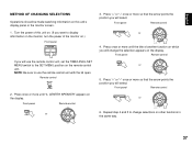
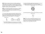
Remote control TIME/LEVEL SET MENU 2. Front panel Remote control SET MENU or 5. Front panel Remote control or 6. Turn the power of this unit's display panel or the monitor screen. 1. Press "+" or "-" once or more so that the arrow points the position you will select. Front ... METHOD OF CHANGING SELECTIONS Operations should be made watching information on this unit on. (If you want to display information on the monitor, turn the power of the monitor on.) Front panel POWER If you will use the remote control unit with the lid open.
Remote control TIME/LEVEL SET MENU 2. Front panel Remote control SET MENU or 5. Front panel Remote control or 6. Turn the power of this unit's display panel or the monitor screen. 1. Press "+" or "-" once or more so that the arrow points the position you will select. Front ... METHOD OF CHANGING SELECTIONS Operations should be made watching information on this unit on. (If you want to display information on the monitor, turn the power of the monitor on.) Front panel POWER If you will use the remote control unit with the lid open.

Owner's Manual
Page 43
PRESET + A/B/C/D/E TUNER DISC PLAY CD PHONO POWER ON VOLUME ROOM 2 OFF 7 5 6 This remote control unit makes input source selections on this unit and controls Yamaha remote control-compatible CD player, tape deck, LD player and/or tuner connected to this unit for the main room. NAMES OF KEYS AND THEIR ...
PRESET + A/B/C/D/E TUNER DISC PLAY CD PHONO POWER ON VOLUME ROOM 2 OFF 7 5 6 This remote control unit makes input source selections on this unit and controls Yamaha remote control-compatible CD player, tape deck, LD player and/or tuner connected to this unit for the main room. NAMES OF KEYS AND THEIR ...

Owner's Manual
Page 44
... control unit (for the second room) in the main room, the input selector keys of this unit. and Canada models) Pressing the POWER ON key turns the power of this remote control unit affect the settings in the second room. CAUTION In some cases, adjustments made using the remote control units... If you switch the input source for the person in the second room to the power-on mode. (In the standby mode, the standby indicator on the front panel is illuminated.) 6 VOLUME ROOM 2 + (up momentarily when the Room 2 remote...
... control unit (for the second room) in the main room, the input selector keys of this unit. and Canada models) Pressing the POWER ON key turns the power of this remote control unit affect the settings in the second room. CAUTION In some cases, adjustments made using the remote control units... If you switch the input source for the person in the second room to the power-on mode. (In the standby mode, the standby indicator on the front panel is illuminated.) 6 VOLUME ROOM 2 + (up momentarily when the Room 2 remote...
Owner's Manual
Page 46
... left and right main speakers. 6. CENTER SPEAKER" in the SET MENU mode to "-10 dB", and adjust each speaker level again. Volume controls on external power amplifiers may decrease the main speaker volume level by pressing the + or -
... left and right main speakers. 6. CENTER SPEAKER" in the SET MENU mode to "-10 dB", and adjust each speaker level again. Volume controls on external power amplifiers may decrease the main speaker volume level by pressing the + or -

Owner's Manual
Page 47
... TIME/LEVEL SET MENU 2. INPUT MODE (TV/DBS) METHOD OF SETTING CHANGE AND ADJUSTMENT Operations should be made watching information on the monitor, turn the power of your system and expand your enjoyment for audio listening and video watching. 1. DYNAMIC RANGE 3. LFE/BASS OUT 8. Front panel Remote control SET or MENU...
... TIME/LEVEL SET MENU 2. INPUT MODE (TV/DBS) METHOD OF SETTING CHANGE AND ADJUSTMENT Operations should be made watching information on the monitor, turn the power of your system and expand your enjoyment for audio listening and video watching. 1. DYNAMIC RANGE 3. LFE/BASS OUT 8. Front panel Remote control SET or MENU...


