

Owner's Manual
Page 3
... ELECTRIC SERVICE EQUIPMENT NEC - INTRODUCTION PREPARATION BASIC OPERATION ADVANCED OPERATION 19 For US customers only: Outdoor Antenna Grounding - If an outside antenna is 300 ohm ribbon lead, change the lead-in harmful interference with regard to proper grounding of the mast and supporting structure, grounding of this unit, be used according to the instructions found to be the source of radio or...
... ELECTRIC SERVICE EQUIPMENT NEC - INTRODUCTION PREPARATION BASIC OPERATION ADVANCED OPERATION 19 For US customers only: Outdoor Antenna Grounding - If an outside antenna is 300 ohm ribbon lead, change the lead-in harmful interference with regard to proper grounding of the mast and supporting structure, grounding of this unit, be used according to the instructions found to be the source of radio or...
Owner's Manual
Page 5
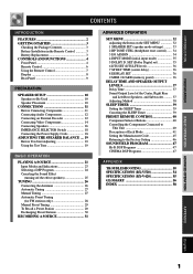
... (Dolby Digital set 35 6 DTS SET (DTS LFE level 36 7 SP DLY TIME (center delay 36 8 DISPLAY SET 36 9 MEM. INTRODUCTION PREPARATION INTRODUCTION CONTENTS INTRODUCTION FEATURES 2 GETTING STARTED 3 Checking the Package Contents 3 Battery Installation in the Remote Control 3 Battery Replacement 3 CONTROLS AND FUNCTIONS 4 Front Panel 4 Remote Control 6 Using the Remote Control 7 Display 8 Rear Panel 9 PREPARATION SPEAKER SETUP 10 Speakers to the Factory Setting 46 SOUND FIELD PROGRAM 47 Hi-Fi DSP Programs 47 CINEMA DSP Programs 47 APPENDIX TROUBLESHOOTING 50 SPECIFICATIONS...
... (Dolby Digital set 35 6 DTS SET (DTS LFE level 36 7 SP DLY TIME (center delay 36 8 DISPLAY SET 36 9 MEM. INTRODUCTION PREPARATION INTRODUCTION CONTENTS INTRODUCTION FEATURES 2 GETTING STARTED 3 Checking the Package Contents 3 Battery Installation in the Remote Control 3 Battery Replacement 3 CONTROLS AND FUNCTIONS 4 Front Panel 4 Remote Control 6 Using the Remote Control 7 Display 8 Rear Panel 9 PREPARATION SPEAKER SETUP 10 Speakers to the Factory Setting 46 SOUND FIELD PROGRAM 47 Hi-Fi DSP Programs 47 CINEMA DSP Programs 47 APPENDIX TROUBLESHOOTING 50 SPECIFICATIONS...

Owner's Manual
Page 6
...remote control, the button name on the remote control is the Owner's Manual for Other Future Formats N Video Signal Input and Output Capability (Including S Video Connections RX-V520 only ) N Optical and Coaxial Digital Signal Input Jacks N SLEEP Timer N Remote Control with 9 Items for Optimizing This Unit for Your Audio/Video System N Test Tone Generator for Easier Speaker Balance Adjustment N 6-Channel External Decoder Input for both the RX-V520 and RX-V420. FEATURES 5-Channel Power Amplification N Minimum RMS Output (0.06% THD, 20 Hz - 20 kHz) RX-V520 [U.S.A. "Dolby", "AC-3", "Pro...
...remote control, the button name on the remote control is the Owner's Manual for Other Future Formats N Video Signal Input and Output Capability (Including S Video Connections RX-V520 only ) N Optical and Coaxial Digital Signal Input Jacks N SLEEP Timer N Remote Control with 9 Items for Optimizing This Unit for Your Audio/Video System N Test Tone Generator for Easier Speaker Balance Adjustment N 6-Channel External Decoder Input for both the RX-V520 and RX-V420. FEATURES 5-Channel Power Amplification N Minimum RMS Output (0.06% THD, 20 Hz - 20 kHz) RX-V520 [U.S.A. "Dolby", "AC-3", "Pro...
Owner's Manual
Page 8
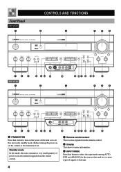
... This receives signals from the remote control. 3 Display This shows various information. 4 INPUT MODE Press this button to select the input mode among AUTO, DTS and ANALOG for the sources that send two or more types of this unit or to this unit. 4 Before turning the power on the power of signals to set the volume at the minimum level. Front Panel RX-V520 1 CONTROLS AND FUNCTIONS 2 3 456 STANDBY /ON D I G I TA L SURROUND BASS TREBLE BALANCE -+ -+ L R SPEAKERS A B ON OFF D I G I TA L VOLUME PROGRAM EFFECT PRESET/TUNING PHONES S VIDEO VIDEO L AUDIO R OPTICAL...
... This receives signals from the remote control. 3 Display This shows various information. 4 INPUT MODE Press this button to select the input mode among AUTO, DTS and ANALOG for the sources that send two or more types of this unit or to this unit. 4 Before turning the power on the power of signals to set the volume at the minimum level. Front Panel RX-V520 1 CONTROLS AND FUNCTIONS 2 3 456 STANDBY /ON D I G I TA L SURROUND BASS TREBLE BALANCE -+ -+ L R SPEAKERS A B ON OFF D I G I TA L VOLUME PROGRAM EFFECT PRESET/TUNING PHONES S VIDEO VIDEO L AUDIO R OPTICAL...
Owner's Manual
Page 9
... Dolby Digital and DTS audio signals except for the LFE channel are turned on the remote control). 7 BASS Turn this control clockwise to increase or counterclockwise to decrease the low-frequency response. 8 TREBLE Turn this button to higher frequencies. In that case, the output levels of the right and left main speakers to compensate for the main speaker system that this button to use . When listening with INPUT l / h (or the input selector buttons on . CONTROLS AND FUNCTIONS r VIDEO AUX jacks Connect an auxiliary audio or video input source...
... Dolby Digital and DTS audio signals except for the LFE channel are turned on the remote control). 7 BASS Turn this control clockwise to increase or counterclockwise to decrease the low-frequency response. 8 TREBLE Turn this button to higher frequencies. In that case, the output levels of the right and left main speakers to compensate for the main speaker system that this button to use . When listening with INPUT l / h (or the input selector buttons on . CONTROLS AND FUNCTIONS r VIDEO AUX jacks Connect an auxiliary audio or video input source...

Owner's Manual
Page 10
... AMP(TUNER) on and standby mode. 4 TEST Press this button to output the test tone for each speaker. 5 A/B/C/D/E, PRESET -/+ These buttons are used to select a preset station. u: To turn up the volume d: To turn down the volume 8 SLEEP Press this button to set the SLEEP timer. 9 -/+ These buttons adjust the settings of the SET MENU and TIME/LEVEL mode. 0 TIME/LEVEL Press this button to control with the remote control. q Input selector buttons These buttons select the input source. If it flashes rapidly several times, press the selected button again. 2 Component selector buttons...
... AMP(TUNER) on and standby mode. 4 TEST Press this button to output the test tone for each speaker. 5 A/B/C/D/E, PRESET -/+ These buttons are used to select a preset station. u: To turn up the volume d: To turn down the volume 8 SLEEP Press this button to set the SLEEP timer. 9 -/+ These buttons adjust the settings of the SET MENU and TIME/LEVEL mode. 0 TIME/LEVEL Press this button to control with the remote control. q Input selector buttons These buttons select the input source. If it flashes rapidly several times, press the selected button again. 2 Component selector buttons...
Owner's Manual
Page 13
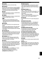
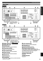
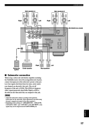
model) 9 Audio component jacks See pages 12 and 13 for connection information. 0 SUBWOOFER jack See page 17 for connection information. 7 AC power cord Connect to a power outlet. 8 AC OUTLET(S) Use these outlets to supply power to your speaker impedance. VIDEO SIGNAL DVD D-TV/CBL IN VCR 1OUT MONITOR OUT VIDEO S VIDEO L DIGITAL OUTPUT AUX CD IN(PLAY) OUT(REC) MD/CD-R DVD D-TV/CBL AUDIO SIGNAL R IN OUT VCR 1 SUB WOOFER OUTPUT R+ A SPEAKERS - - +L MAIN B CENTER REAR R (SURROUND) L + - IMPEDANCE SELECTOR SET BEFORE POWER ON MAIN A OR B: 8 MIN. /SPEAKER A ...
model) 9 Audio component jacks See pages 12 and 13 for connection information. 0 SUBWOOFER jack See page 17 for connection information. 7 AC power cord Connect to a power outlet. 8 AC OUTLET(S) Use these outlets to supply power to your speaker impedance. VIDEO SIGNAL DVD D-TV/CBL IN VCR 1OUT MONITOR OUT VIDEO S VIDEO L DIGITAL OUTPUT AUX CD IN(PLAY) OUT(REC) MD/CD-R DVD D-TV/CBL AUDIO SIGNAL R IN OUT VCR 1 SUB WOOFER OUTPUT R+ A SPEAKERS - - +L MAIN B CENTER REAR R (SURROUND) L + - IMPEDANCE SELECTOR SET BEFORE POWER ON MAIN A OR B: 8 MIN. /SPEAKER A ...
Owner's Manual
Page 21
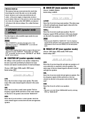
.... /SPEAKER A + B:16 MIN. /SPEAKER CENTER : 8 MIN. /SPEAKER REAR : 8 MIN. /SPEAKER MAIN A OR B: 4 MIN. /SPEAKER A + B: 8 MIN. /SPEAKER CENTER : 6 MIN. /SPEAKER REAR : 6 MIN. /SPEAKER SUB WOOFER OUTPUT AC OUTLETS SWITCHED 100W MAX. TOTAL Left (RX-V520/U.S.A. Low bass signals distributed from the main, center and/or rear channels are directed to this jack. (The cut-off frequency of this jack is 90 Hz.) The LFE (low-frequency effect) signals generated when Dolby Digital or DTS is decoded are also directed if they are assigned to the operation instructions for the subwoofer...
.... /SPEAKER A + B:16 MIN. /SPEAKER CENTER : 8 MIN. /SPEAKER REAR : 8 MIN. /SPEAKER MAIN A OR B: 4 MIN. /SPEAKER A + B: 8 MIN. /SPEAKER CENTER : 6 MIN. /SPEAKER REAR : 6 MIN. /SPEAKER SUB WOOFER OUTPUT AC OUTLETS SWITCHED 100W MAX. TOTAL Left (RX-V520/U.S.A. Low bass signals distributed from the main, center and/or rear channels are directed to this jack. (The cut-off frequency of this jack is 90 Hz.) The LFE (low-frequency effect) signals generated when Dolby Digital or DTS is decoded are also directed if they are assigned to the operation instructions for the subwoofer...
Owner's Manual
Page 23
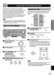
...L VOLUME PROGRAM EFFECT PRESET/TUNING PHONES S VIDEO VIDEO L AUDIO R OPTICAL A/B/C/D/E PRESET /TUNING FM/AM EDIT MEMORY TUNING MODE MAN'L/AUTO FM AUTO/MAN'L MONO INPUT MODE INPUT 6CH INPUT SILENT VIDEO AUX 43 1 Set the volume at your listening position with the remote control. 1 3 5 2,6 1 Press AMP(TUNER) on the component selector. 2 Press TEST. STANDBY /ON 3 Press SPEAKERS A or B to select the main speakers to be sure to unplug the headphones from the center speaker, check the setting of the digital sound field processor, the Dolby Pro Logic decoder, Dolby Digital...
...L VOLUME PROGRAM EFFECT PRESET/TUNING PHONES S VIDEO VIDEO L AUDIO R OPTICAL A/B/C/D/E PRESET /TUNING FM/AM EDIT MEMORY TUNING MODE MAN'L/AUTO FM AUTO/MAN'L MONO INPUT MODE INPUT 6CH INPUT SILENT VIDEO AUX 43 1 Set the volume at your listening position with the remote control. 1 3 5 2,6 1 Press AMP(TUNER) on the component selector. 2 Press TEST. STANDBY /ON 3 Press SPEAKERS A or B to select the main speakers to be sure to unplug the headphones from the center speaker, check the setting of the digital sound field processor, the Dolby Pro Logic decoder, Dolby Digital...
Owner's Manual
Page 26
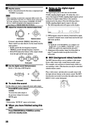
... indication will be controlled with a sound from a video source with the remote control. Note • If "MAIN SP" in the standby mode. Play a video source, and then select an audio source with INPUT l / h on the display. PLAYING A SOURCE 5 Play the source. BASS TREBLE BALANCE -+ -+ L R Front panel 7 Use the digital sound field processor. PCM K HZ 2. Note • When controlling an audio/video component (MD recorder, CD player, DVD player, tape deck, etc.) with the remote control, press one of the component selector buttons, (TAPE/MD, CD, DVD/ LD, etc.), which...
... indication will be controlled with a sound from a video source with the remote control. Note • If "MAIN SP" in the standby mode. Play a video source, and then select an audio source with INPUT l / h on the display. PLAYING A SOURCE 5 Play the source. BASS TREBLE BALANCE -+ -+ L R Front panel 7 Use the digital sound field processor. PCM K HZ 2. Note • When controlling an audio/video component (MD recorder, CD player, DVD player, tape deck, etc.) with the remote control, press one of the component selector buttons, (TAPE/MD, CD, DVD/ LD, etc.), which...
Owner's Manual
Page 28
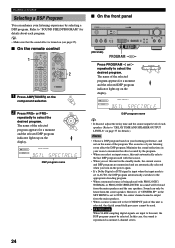
... S VIDEO VIDEO L AUDIO R OPTICAL A/B/C/D/E PRESET /TUNING FM/AM EDIT MEMORY TUNING MODE MAN'L/AUTO FM AUTO/MAN'L MONO INPUT MODE INPUT 6CH INPUT (RX-V520) SILENT VIDEO AUX PROGRAM / Press PROGRAM l or h repeatedly to this unit, the DSP program cannot be used with PRO LOGIC/ NORMAL or PRO LOGIC/ENHANCED, no sound will be heard from the main speakers. • When a source connected to the 6CH INPUT jack of the program. Minimize the sound reflections in the SET MENU is set to AUTO, the DSP program automatically switches to "DELAY TIME...
... S VIDEO VIDEO L AUDIO R OPTICAL A/B/C/D/E PRESET /TUNING FM/AM EDIT MEMORY TUNING MODE MAN'L/AUTO FM AUTO/MAN'L MONO INPUT MODE INPUT 6CH INPUT (RX-V520) SILENT VIDEO AUX PROGRAM / Press PROGRAM l or h repeatedly to this unit, the DSP program cannot be used with PRO LOGIC/ NORMAL or PRO LOGIC/ENHANCED, no sound will be heard from the main speakers. • When a source connected to the 6CH INPUT jack of the program. Minimize the sound reflections in the SET MENU is set to AUTO, the DSP program automatically switches to "DELAY TIME...

Owner's Manual
Page 35
.... Front panel 2 Select the source you play back a video source that uses scrambled or encoded signals to prevent it from records, CDs, radio, etc. For DVDs and CDs encoded with DTS Only 2-channel analog audio signals may infringe copyright laws. • RX-V520 only Composite video and S video signals pass independently through this unit. 4 Play the source and then turn up the volume to confirm the input source. Refer to the instructions for these components. 1,4 STANDBY /ON D I G I TA L SURROUND BASS TREBLE BALANCE -+ -+ L R SPEAKERS...
.... Front panel 2 Select the source you play back a video source that uses scrambled or encoded signals to prevent it from records, CDs, radio, etc. For DVDs and CDs encoded with DTS Only 2-channel analog audio signals may infringe copyright laws. • RX-V520 only Composite video and S video signals pass independently through this unit. 4 Play the source and then turn up the volume to confirm the input source. Refer to the instructions for these components. 1,4 STANDBY /ON D I G I TA L SURROUND BASS TREBLE BALANCE -+ -+ L R SPEAKERS...
Owner's Manual
Page 37
... main channel are directed to the factory settings. The lowfrequency signals (90 Hz and below ) of the center channel signal is directed to the speakers selected with "BASS OUT". NON Select this feature to the left and right main channel signal is connected to the speakers selected with "BASS OUT". The entire range of the rear channel are directed to select suitable output modes for "REAR LR SP". Note • When you select MAIN for "BASS OUT", the low-frequency signals (90...
... main channel are directed to the factory settings. The lowfrequency signals (90 Hz and below ) of the center channel signal is directed to the speakers selected with "BASS OUT". NON Select this feature to the left and right main channel signal is connected to the speakers selected with "BASS OUT". The entire range of the rear channel are directed to select suitable output modes for "REAR LR SP". Note • When you select MAIN for "BASS OUT", the low-frequency signals (90...
Owner's Manual
Page 39
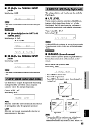
... BASIC OPERATION ADVANCED OPERATION PREPARATION INTRODUCTION MAX Dialog level Output level Input level STD Dialog level H-LEVEL CUT 0.0 1.0 MIN Dialog level Output level Output level 1.0 Note 0.0 L-LEVEL BST Input level Input level • When you select MIN, the sound output may be faint because some Dolby Digital signals are not compatible with the source component connected to more than once for the same type of jack. SET MENU 5 DOLBY D. RX-V420 I LFE LEVEL Use this unit to automatically detect the type of input signal and select the appropriate input mode. Control...
... BASIC OPERATION ADVANCED OPERATION PREPARATION INTRODUCTION MAX Dialog level Output level Input level STD Dialog level H-LEVEL CUT 0.0 1.0 MIN Dialog level Output level Output level 1.0 Note 0.0 L-LEVEL BST Input level Input level • When you select MIN, the sound output may be faint because some Dolby Digital signals are not compatible with the source component connected to more than once for the same type of jack. SET MENU 5 DOLBY D. RX-V420 I LFE LEVEL Use this unit to automatically detect the type of input signal and select the appropriate input mode. Control...
Owner's Manual
Page 40
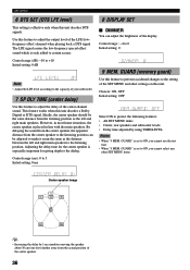
... brightness of the LFE (lowfrequency effect) channel when playing back a DTS signal. GUARD (memory guard) Use this feature to adjust the output level of the display. Choices: ON, OFF Initial setting: OFF Select ON to certain scenes. GUARD" is set to ON, you cannot use the test tone. • When "9 MEM. SET MENU 6 DTS SET (DTS LFE level) This setting is effective only when this unit decodes a Dolby Digital or DTS signal. By delaying the sound from the center speaker, the apparent...
... brightness of the LFE (lowfrequency effect) channel when playing back a DTS signal. GUARD (memory guard) Use this feature to adjust the output level of the display. Choices: ON, OFF Initial setting: OFF Select ON to certain scenes. GUARD" is set to ON, you cannot use the test tone. • When "9 MEM. SET MENU 6 DTS SET (DTS LFE level) This setting is effective only when this unit decodes a Dolby Digital or DTS signal. By delaying the sound from the center speaker, the apparent...
Owner's Manual
Page 44
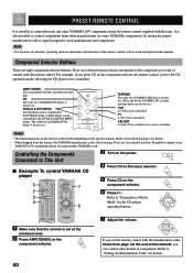
... description in the DVD/LD and DVD MENU modes. Controlling the Components Connected to "Setting the Manufacturer Code" for details. • When shipped from page i at the minimum level. 2 Press AMP(TUNER) on batteries, operating distance and names and functions of these buttons which corresponds to the component you can be controlled. Refer to This Unit I Example: To control YAMAHA CD player 5 7 2 3 4 6 3 Turn on the power. 4 Press CD on the input selector. 5 Press...
... description in the DVD/LD and DVD MENU modes. Controlling the Components Connected to "Setting the Manufacturer Code" for details. • When shipped from page i at the minimum level. 2 Press AMP(TUNER) on batteries, operating distance and names and functions of these buttons which corresponds to the component you can be controlled. Refer to This Unit I Example: To control YAMAHA CD player 5 7 2 3 4 6 3 Turn on the power. 4 Press CD on the input selector. 5 Press...

Owner's Manual
Page 50
... TAPE/MD Component TV Cable TV VCR DVD player CD player MD recorder Code 0101 0006 0002 0008 (YAMAHA DVD player) 0005 (YAMAHA CD player) 0024 (YAMAHA MD recorder) Set component We recommend that you write all modes 1 Press one of the component selector buttons which corresponds to the component to be returned to the factory-set codes in each mode 1 Press one of the component selector buttons other than AMP(TUNER). 2 Press both VOLUME buttons (u/d) at the same time...
... TAPE/MD Component TV Cable TV VCR DVD player CD player MD recorder Code 0101 0006 0002 0008 (YAMAHA DVD player) 0005 (YAMAHA CD player) 0024 (YAMAHA MD recorder) Set component We recommend that you write all modes 1 Press one of the component selector buttons which corresponds to the component to be returned to the factory-set codes in each mode 1 Press one of the component selector buttons other than AMP(TUNER). 2 Press both VOLUME buttons (u/d) at the same time...

Owner's Manual
Page 54
... of jack (between composites, S-VIDEOs, or components) for the video are not secure. The IMPEDANCE SELECTOR switch on the rear panel is pressed, or enters in the standby mode. Secure the connections. The sound is muted. The sleep timer has functioned. The picture does not appear. Only the speaker on the power, and play the source again. Incorrect cable connections. Digital signals other than its respective connection. Press MUTE or any operation buttons to...
... of jack (between composites, S-VIDEOs, or components) for the video are not secure. The IMPEDANCE SELECTOR switch on the rear panel is pressed, or enters in the standby mode. Secure the connections. The sound is muted. The sleep timer has functioned. The picture does not appear. Only the speaker on the power, and play the source again. Incorrect cable connections. Digital signals other than its respective connection. Press MUTE or any operation buttons to...

Owner's Manual
Page 62
... 12 Power supply cords 18 Speakers 16 Video components (DVD player, VCR and TV/digital TV or cable TV/satellite tuner 14 D Delay time 37 Display 8 DISPLAY SET (SET MENU 36 DOLBY D. GUARD (SET MENU 36 Muting 22 P Package contents 3 PCM 57 Playing 21 Power supply cords 18 Preset stations Exchanging preset station 30 To recall a preset station 29 Presetting tuning Automatic preset tuning 28 Manual preset tuning 29 R Rear panel 9 Recording 31 Remote control Basic operation 6 Batteries 3 Operation range 7 Setup codes 45 S Sampling frequency (RX-V520 only 22, 57 SET MENU 32...
... 12 Power supply cords 18 Speakers 16 Video components (DVD player, VCR and TV/digital TV or cable TV/satellite tuner 14 D Delay time 37 Display 8 DISPLAY SET (SET MENU 36 DOLBY D. GUARD (SET MENU 36 Muting 22 P Package contents 3 PCM 57 Playing 21 Power supply cords 18 Preset stations Exchanging preset station 30 To recall a preset station 29 Presetting tuning Automatic preset tuning 28 Manual preset tuning 29 R Rear panel 9 Recording 31 Remote control Basic operation 6 Batteries 3 Operation range 7 Setup codes 45 S Sampling frequency (RX-V520 only 22, 57 SET MENU 32...

Owner's Manual
Page 67
...Video signal R V Video signal O Optical signal Signal flow V728210 RX-V520/RX-V420 (ML) DVD player OPTICAL AUDIO OUT L R Connection Guide (when listening to a digital 5.1-channel source) S VIDEO OUT VIDEO OUT Main speakers A Main speakers B OPTICAL OUT AUDIO OUT S VIDEO VIDEO OUT OUT O LR V S R LR L DIGITAL INPUT CD AM ANT GND TUNER FM ANT COAXIAL OPTICAL D-TV/CBL DVD 6CH INPUT MAIN SURROUND CENTER L L MD/CD-R OPTICAL MD/CD-R R R SUB WOOFER 75 UNBAL. VIDEO SIGNAL DVD D-TV/CBL IN VCR 1OUT MONITOR OUT VIDEO S VIDEO L DIGITAL OUTPUT AUX CD IN(PLAY...
...Video signal R V Video signal O Optical signal Signal flow V728210 RX-V520/RX-V420 (ML) DVD player OPTICAL AUDIO OUT L R Connection Guide (when listening to a digital 5.1-channel source) S VIDEO OUT VIDEO OUT Main speakers A Main speakers B OPTICAL OUT AUDIO OUT S VIDEO VIDEO OUT OUT O LR V S R LR L DIGITAL INPUT CD AM ANT GND TUNER FM ANT COAXIAL OPTICAL D-TV/CBL DVD 6CH INPUT MAIN SURROUND CENTER L L MD/CD-R OPTICAL MD/CD-R R R SUB WOOFER 75 UNBAL. VIDEO SIGNAL DVD D-TV/CBL IN VCR 1OUT MONITOR OUT VIDEO S VIDEO L DIGITAL OUTPUT AUX CD IN(PLAY...


