
MCXSP10 Manual
Page 2
..., and these openings must not be taken to dangerous voltage or other ). The safety and operating instructions should be adhered to . 11 Power Sources - Do not use instructions should be placed in a built-in a risk of the product should follow the manufacturer's instructions, and..., bracket, or table. The exclamation point within the product's enclosure that may cause the product and cart combination to lightning and power-line surges. 15 Power Lines - This product should be equipped with them , paying particular attention to cords at plugs, convenience receptacles, and the point ...
..., and these openings must not be taken to dangerous voltage or other ). The safety and operating instructions should be adhered to . 11 Power Sources - Do not use instructions should be placed in a built-in a risk of the product should follow the manufacturer's instructions, and..., bracket, or table. The exclamation point within the product's enclosure that may cause the product and cart combination to lightning and power-line surges. 15 Power Lines - This product should be equipped with them , paying particular attention to cords at plugs, convenience receptacles, and the point ...

MCXSP10 Manual
Page 3
... CODE ANTENNA LEAD IN WIRE ANTENNA DISCHARGE UNIT (NEC SECTION 810-20) GROUNDING CONDUCTORS (NEC SECTION 810-21) GROUND CLAMPS POWER SERVICE GROUNDING ELECTRODE SYSTEM (NEC ART 250. Compliance with FCC regulations does not guarantee that interference will not occur in fire,... service. 20 Replacement Parts - EXAMPLE OF ANTENNA GROUNDING MAST GROUND CLAMP ELECTRIC SERVICE EQUIPMENT NEC - Modifications not expressly approved by Yamaha may cause interference harmful to those controls that are covered by the operating instructions as radiators, heat registers, stoves, or other ...
... CODE ANTENNA LEAD IN WIRE ANTENNA DISCHARGE UNIT (NEC SECTION 810-20) GROUNDING CONDUCTORS (NEC SECTION 810-21) GROUND CLAMPS POWER SERVICE GROUNDING ELECTRODE SYSTEM (NEC ART 250. Compliance with FCC regulations does not guarantee that interference will not occur in fire,... service. 20 Replacement Parts - EXAMPLE OF ANTENNA GROUNDING MAST GROUND CLAMP ELECTRIC SERVICE EQUIPMENT NEC - Modifications not expressly approved by Yamaha may cause interference harmful to those controls that are covered by the operating instructions as radiators, heat registers, stoves, or other ...

MCXSP10 Manual
Page 4
... please read the "TROUBLESHOOTING" section on the surface of time (i.e. this unit, do not place: - YAMAHA will not be set for any damage resulting from the AC power source as long as they may cause damage and/or discoloration on common operating errors before concluding that lets ...outlet or this unit during a lightning storm. 14 Do not attempt to liquid dripping or splashing. and, most out of power. other than specified is too late, YAMAHA and the Electronic Industries Association's Consumer Electronics Group recommend you to hot, and do not pull the cord. 11 Do ...
... please read the "TROUBLESHOOTING" section on the surface of time (i.e. this unit, do not place: - YAMAHA will not be set for any damage resulting from the AC power source as long as they may cause damage and/or discoloration on common operating errors before concluding that lets ...outlet or this unit during a lightning storm. 14 Do not attempt to liquid dripping or splashing. and, most out of power. other than specified is too late, YAMAHA and the Electronic Industries Association's Consumer Electronics Group recommend you to hot, and do not pull the cord. 11 Do ...

MCXSP10 Manual
Page 5
...18 Connecting a DVD player, a DVD recorder, a VCR or an STB 19 Connecting a CD player, an MD player or a tape deck 21 Connecting a YAMAHA iPod universal dock ........ 22 Connecting a multi-format player or an external decoder 23 Connecting a game console, a video camera or a portable audio player 23 ...Connecting the FM and AM antennas 24 Connecting the power cable 25 Setting the speaker impedance 26 Turning on and off the power 27 BASIC SETUP 28 BASIC OPERATION PLAYBACK 31 USING AUDIO FEATURES 33 Using SILENT CINEMA 33 Muting the...
...18 Connecting a DVD player, a DVD recorder, a VCR or an STB 19 Connecting a CD player, an MD player or a tape deck 21 Connecting a YAMAHA iPod universal dock ........ 22 Connecting a multi-format player or an external decoder 23 Connecting a game console, a video camera or a portable audio player 23 ...Connecting the FM and AM antennas 24 Connecting the power cable 25 Setting the speaker impedance 26 Turning on and off the power 27 BASIC SETUP 28 BASIC OPERATION PLAYBACK 31 USING AUDIO FEATURES 33 Using SILENT CINEMA 33 Muting the...

MCXSP10 Manual
Page 6
...night listening modes ◆ Remote control with preset remote control codes, backlighting input selector buttons, and an iPod (stationed in a YAMAHA iPod universal dock connected to the DOCK terminal) controlling capability ◆ Zone 2 custom installation facility ◆ Zone switching capability ...XM Satellite Radio (U.S.A. In case the button names differ between the manual and product, the product has priority. FEATURES FEATURES Built-in 6-channel power amplifier ◆ Minimum RMS output power (0.06% THD, 20 Hz to 20 kHz, 8 Ω) Front: 95 W + 95 W Center: 95 W Surround: 95 ...
...night listening modes ◆ Remote control with preset remote control codes, backlighting input selector buttons, and an iPod (stationed in a YAMAHA iPod universal dock connected to the DOCK terminal) controlling capability ◆ Zone 2 custom installation facility ◆ Zone switching capability ...XM Satellite Radio (U.S.A. In case the button names differ between the manual and product, the product has priority. FEATURES FEATURES Built-in 6-channel power amplifier ◆ Minimum RMS output power (0.06% THD, 20 Hz to 20 kHz, 8 Ω) Front: 95 W + 95 W Center: 95 W Surround: 95 ...

MCXSP10 Manual
Page 7
...2 Insert the two supplied batteries (AA, R6, UM-3) according to the polarity markings (+ and -) on the inside of the batteries if you received all of the battery compartment. 3 Snap the battery compartment cover back into contact with general house waste; Notes • Change all of the memory... may be cleared. Read the packaging carefully as alkaline and manganese batteries) together. Remote control CODE SET TRANSMIT POWER TV POWER AV STANDBY POWER CD DVD MD CD-R CBL DTV SLEEP XM TUNER MULTI CH IN V-AUX DVR TV VOL TV CH AMP VOLUME SOURCE TV ...
...2 Insert the two supplied batteries (AA, R6, UM-3) according to the polarity markings (+ and -) on the inside of the batteries if you received all of the battery compartment. 3 Snap the battery compartment cover back into contact with general house waste; Notes • Change all of the memory... may be cleared. Read the packaging carefully as alkaline and manganese batteries) together. Remote control CODE SET TRANSMIT POWER TV POWER AV STANDBY POWER CD DVD MD CD-R CBL DTV SLEEP XM TUNER MULTI CH IN V-AUX DVR TV VOL TV CH AMP VOLUME SOURCE TV ...

MCXSP10 Manual
Page 8
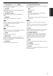
...source. I JK (U.S.A. The colon (:) is not displayed in the front panel display (see page 45). • Adjusts the level of power in order to receive infrared signals from the remote control (see page 8). 4 Front panel display Shows information about the operational status of this button for more ...unit can reproduce sound. • This button is operational only when MASTER ON/OFF is pressed inward to the ON position. 3 Remote control sensor Receives signals from the remote control. • When you want to start automatic preset tuning (see page 35). 7 MEMORY (MAN'L/AUTO FM) Stores...
...source. I JK (U.S.A. The colon (:) is not displayed in the front panel display (see page 45). • Adjusts the level of power in order to receive infrared signals from the remote control (see page 8). 4 Front panel display Shows information about the operational status of this button for more ...unit can reproduce sound. • This button is operational only when MASTER ON/OFF is pressed inward to the ON position. 3 Remote control sensor Receives signals from the remote control. • When you want to start automatic preset tuning (see page 35). 7 MEMORY (MAN'L/AUTO FM) Stores...

MCXSP10 Manual
Page 10
..., see page 42). - RETURN XM MEMORY REC DISC SKIP ENTER A-E/CAT. Press this button repeatedly to toggle as the input source. 1 2 3 CODE SET TRANSMIT POWER TV POWER AV STANDBY POWER CD DVD MD CD-R CBL DTV SLEEP XM TUNER MULTI CH IN 0 A B C D ■ Controlling this unit Set the component selector switch to AMP to...
..., see page 42). - RETURN XM MEMORY REC DISC SKIP ENTER A-E/CAT. Press this button repeatedly to toggle as the input source. 1 2 3 CODE SET TRANSMIT POWER TV POWER AV STANDBY POWER CD DVD MD CD-R CBL DTV SLEEP XM TUNER MULTI CH IN 0 A B C D ■ Controlling this unit Set the component selector switch to AMP to...
MCXSP10 Manual
Page 11
... decoder, etc. (see page 33). K DISPLAY Selects the on the front panel is given to the one set the remote control codes for DTV/ CBL. B POWER Turns on . CONTROLS AND FUNCTIONS F Component selector switch Selects the operation mode of the remote control buttons in the shaded area. H STRAIGHT (EFFECT) Turns the...
... decoder, etc. (see page 33). K DISPLAY Selects the on the front panel is given to the one set the remote control codes for DTV/ CBL. B POWER Turns on . CONTROLS AND FUNCTIONS F Component selector switch Selects the operation mode of the remote control buttons in the shaded area. H STRAIGHT (EFFECT) Turns the...

MCXSP10 Manual
Page 12
... AUTO/MAN'L LEVEL INPUT DISPLAY STRAIGHT TONE CONTROL INPUT MODE MULTI CH INPUT EFFECT VIDEO VIDEO AUX L AUDIO R PORTABLE 30 30 CODE SET TRANSMIT POWER TV POWER AV STANDBY POWER MD SLEEP CD CD-R XM CBL MULTI CH IN DVD DTV TUNER V-AUX DVR TV VOL TV CH AMP VOLUME SOURCE TV TV MUTE...
... AUTO/MAN'L LEVEL INPUT DISPLAY STRAIGHT TONE CONTROL INPUT MODE MULTI CH INPUT EFFECT VIDEO VIDEO AUX L AUDIO R PORTABLE 30 30 CODE SET TRANSMIT POWER TV POWER AV STANDBY POWER MD SLEEP CD CD-R XM CBL MULTI CH IN DVD DTV TUNER V-AUX DVR TV VOL TV CH AMP VOLUME SOURCE TV TV MUTE...

MCXSP10 Manual
Page 15
... 75Ω UNBAL. model only) See page 52 for connection information. A REMOTE jacks See page 95 for connection information. E AC OUTLET(S) Use to supply power to connect a YAMAHA iPod universal dock (such as YDS-10 sold separately) where your other audiovisual components. See page 22 for connection information. 0 COMPONENT VIDEO jacks See...
... 75Ω UNBAL. model only) See page 52 for connection information. A REMOTE jacks See page 95 for connection information. E AC OUTLET(S) Use to supply power to connect a YAMAHA iPod universal dock (such as YDS-10 sold separately) where your other audiovisual components. See page 22 for connection information. 0 COMPONENT VIDEO jacks See...
MCXSP10 Manual
Page 22
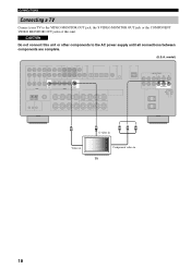
CAUTION Do not connect this unit or other components to the VIDEO MONITOR OUT jack, the S VIDEO MONITOR OUT jack or the COMPONENT VIDEO MONITOR OUT jacks of this unit. model) VIDEO MONITOR OUT S VIDEO MONITOR OUT COMPONENT VIDEO Y PB PR MONITOR OUT V Video in S S-video in Y PB PR Component video in TV 18 CONNECTIONS Connecting a TV Connect your TV to the AC power supply until all connections between components are complete. (U.S.A.
CAUTION Do not connect this unit or other components to the VIDEO MONITOR OUT jack, the S VIDEO MONITOR OUT jack or the COMPONENT VIDEO MONITOR OUT jacks of this unit. model) VIDEO MONITOR OUT S VIDEO MONITOR OUT COMPONENT VIDEO Y PB PR MONITOR OUT V Video in S S-video in Y PB PR Component video in TV 18 CONNECTIONS Connecting a TV Connect your TV to the AC power supply until all connections between components are complete. (U.S.A.

MCXSP10 Manual
Page 23
... "VIDEO CONV." When recording a source, you connected your TV to the VIDEO MONITOR OUT jack of this unit or other components to the AC power supply until all connections between each DIGITAL INPUT or DIGITAL OUTPUT jack, select the corresponding setting for "OPTICAL OUT", "OPTICAL IN", or "COAXIAL IN...of video connections as those made for your TV (see page 18). model) COMPONENT VIDEO DVD Y PB PR 19 The cable TV receiver and the satellite receiver are examples of video connections as those made for your TV (see page 18). For example, if you must make the same type...
... "VIDEO CONV." When recording a source, you connected your TV to the VIDEO MONITOR OUT jack of this unit or other components to the AC power supply until all connections between each DIGITAL INPUT or DIGITAL OUTPUT jack, select the corresponding setting for "OPTICAL OUT", "OPTICAL IN", or "COAXIAL IN...of video connections as those made for your TV (see page 18). model) COMPONENT VIDEO DVD Y PB PR 19 The cable TV receiver and the satellite receiver are examples of video connections as those made for your TV (see page 18). For example, if you must make the same type...
MCXSP10 Manual
Page 25
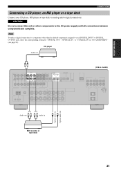
CAUTION Do not connect this unit or other than the default component assigned to the AC power supply until all connections between components are complete. CD player Audio out RL AUDIO IN MD/ OUT CD (PLAY) CD-R (REC) DIGITAL OUTPUT MD/CD-R ...
CAUTION Do not connect this unit or other than the default component assigned to the AC power supply until all connections between components are complete. CD player Audio out RL AUDIO IN MD/ OUT CD (PLAY) CD-R (REC) DIGITAL OUTPUT MD/CD-R ...

MCXSP10 Manual
Page 26
...complete, station your iPod using its dedicated cable compatible with the DOCK terminal of this unit. • Once your iPod is stationed in a YAMAHA iPod universal dock (such as YDS-10 sold separately) connected to the DOCK terminal of the iPod adapters supplied with the DOCK terminal on the..."iPod connected" appears in the front panel display and the DOCK indicator lights up in the YAMAHA iPod universal dock. If the connection between your iPod and this unit or other components to the AC power supply until all connections between your iPod and this unit is turned on. • Depending...
...complete, station your iPod using its dedicated cable compatible with the DOCK terminal of this unit. • Once your iPod is stationed in a YAMAHA iPod universal dock (such as YDS-10 sold separately) connected to the DOCK terminal of the iPod adapters supplied with the DOCK terminal on the..."iPod connected" appears in the front panel display and the DOCK indicator lights up in the YAMAHA iPod universal dock. If the connection between your iPod and this unit or other components to the AC power supply until all connections between your iPod and this unit is turned on. • Depending...
MCXSP10 Manual
Page 27
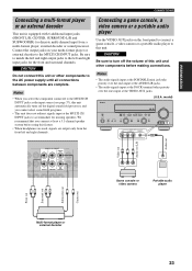
... L/R jacks. • The audio signals input at the DOCK terminal takes priority over the ones input at the MULTI CH INPUT jacks to the AC power supply until all connections between components are output only from a multi-format player, external decoder or sound processor. PREPARATION CONNECTIONS Connecting a multi-format player or...
... L/R jacks. • The audio signals input at the DOCK terminal takes priority over the ones input at the MULTI CH INPUT jacks to the AC power supply until all connections between components are output only from a multi-format player, external decoder or sound processor. PREPARATION CONNECTIONS Connecting a multi-format player or...
MCXSP10 Manual
Page 29
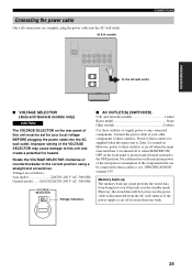
...) U.K. Memory back-up The memory back-up circuit prevents the stored data from being lost in the standby mode. However, power to any connected components. Power to these outlet(s) is pressed and released outward to this unit must be set for more than one week. 25 Improper setting... of your local voltage BEFORE plugging the power cable into the AC wall outlet. (U.S.A. and Australia models 1 outlet Korea model None Other models 2 outlets Use these outlet(s). For information...
...) U.K. Memory back-up The memory back-up circuit prevents the stored data from being lost in the standby mode. However, power to any connected components. Power to these outlet(s) is pressed and released outward to this unit must be set for more than one week. 25 Improper setting... of your local voltage BEFORE plugging the power cable into the AC wall outlet. (U.S.A. and Australia models 1 outlet Korea model None Other models 2 outlets Use these outlet(s). For information...

MCXSP10 Manual
Page 31
... Front panel Remote control • Press MAIN ZONE ON/OFF on the front panel (or POWER on the remote control) to the standby mode. MASTER ON OFF Front panel • Press...the front panel again to release it outward to the OFF position to turn off the power When all connections are operational only when MASTER ON/OFF is pressed inward to turn on the main...zone. model) CODE SET TRANSMIT POWER TV POWER AV STANDBY POWER CD DVD MD CD-R CBL DTV SLEEP XM TUNER MULTI CH IN V-AUX DVR TV VOL TV CH AMP VOLUME SOURCE TV STANDBY POWER ■ Turning on this ...
... Front panel Remote control • Press MAIN ZONE ON/OFF on the front panel (or POWER on the remote control) to the standby mode. MASTER ON OFF Front panel • Press...the front panel again to release it outward to the OFF position to turn off the power When all connections are operational only when MASTER ON/OFF is pressed inward to turn on the main...zone. model) CODE SET TRANSMIT POWER TV POWER AV STANDBY POWER CD DVD MD CD-R CBL DTV SLEEP XM TUNER MULTI CH IN V-AUX DVR TV VOL TV CH AMP VOLUME SOURCE TV STANDBY POWER ■ Turning on this ...

MCXSP10 Manual
Page 32
... 9 LEVEL TITLE BAND ENHANCER 0 NIGHT 10 PRESET/CH STRAIGHT ENT. DISPLAY AUDIO 2,13 3-12 4 Press ENTER to the previous menu level. 1 CODE SET TRANSMIT POWER TV POWER AV STANDBY POWER CD DVD MD CD-R CBL DTV SLEEP XM TUNER MULTI CH IN V-AUX DVR TV VOL TV CH AMP VOLUME SOURCE TV (U.S.A. PRESET/CH...
... 9 LEVEL TITLE BAND ENHANCER 0 NIGHT 10 PRESET/CH STRAIGHT ENT. DISPLAY AUDIO 2,13 3-12 4 Press ENTER to the previous menu level. 1 CODE SET TRANSMIT POWER TV POWER AV STANDBY POWER CD DVD MD CD-R CBL DTV SLEEP XM TUNER MULTI CH IN V-AUX DVR TV VOL TV CH AMP VOLUME SOURCE TV (U.S.A. PRESET/CH...

MCXSP10 Manual
Page 35
...'L/AUTO FM AUTO/MAN'L LEVEL INPUT DISPLAY STRAIGHT TONE CONTROL INPUT MODE MULTI CH INPUT EFFECT VIDEO VIDEO AUX L AUDIO R PORTABLE 2 6,7 6 3 3 2 CODE SET TRANSMIT POWER TV POWER AV STANDBY POWER CD DVD MD CD-R CBL DTV SLEEP XM TUNER MULTI CH IN V-AUX DVR TV VOL TV CH AMP VOLUME SOURCE TV TV MUTE...
...'L/AUTO FM AUTO/MAN'L LEVEL INPUT DISPLAY STRAIGHT TONE CONTROL INPUT MODE MULTI CH INPUT EFFECT VIDEO VIDEO AUX L AUDIO R PORTABLE 2 6,7 6 3 3 2 CODE SET TRANSMIT POWER TV POWER AV STANDBY POWER CD DVD MD CD-R CBL DTV SLEEP XM TUNER MULTI CH IN V-AUX DVR TV VOL TV CH AMP VOLUME SOURCE TV TV MUTE...


