
Owners Manual
Page 5
...airwave tuner 25 Connecting a portable audio player 26 Connecting other components 97 Using the TV macro 100 BASIC OPERATION Playback Selecting the input source Playing back sources Adjusting the volume FM tuning FM controls and functions Automatic tuning ADDITIONAL INFORMATION 45 Troubleshooting 45 Glossary 46 ...MEMORY PROTECT 89 Setting the MAX VOLUME 90 Setting the TURN ON VOLUME 90 Setting the DEMO MODE 91 Setting the PANEL INPUT KEy 92 Disabling the front panel keys 93 Setting the FACTORY PRESET 94 Remote control features 96 Setting remote control codes ...
...airwave tuner 25 Connecting a portable audio player 26 Connecting other components 97 Using the TV macro 100 BASIC OPERATION Playback Selecting the input source Playing back sources Adjusting the volume FM tuning FM controls and functions Automatic tuning ADDITIONAL INFORMATION 45 Troubleshooting 45 Glossary 46 ...MEMORY PROTECT 89 Setting the MAX VOLUME 90 Setting the TURN ON VOLUME 90 Setting the DEMO MODE 91 Setting the PANEL INPUT KEy 92 Disabling the front panel keys 93 Setting the FACTORY PRESET 94 Remote control features 96 Setting remote control codes ...
Owners Manual
Page 11
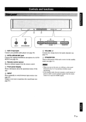
Outputs a test tone to switch between input sources (see page 45). Controls the volume level of all audio channels (see page 47). !J) STANDBY/ON Turns on the power of this unit or ... page 36). @ Remote control sensor Receives infrared signals from the remote control. @ Front panel display Shows information about the operational status of this unit. ® INPUT Press repeatedly to experience the sound beam (see page 26). ® INTELLIBEAM MIC jack Connect the supplied IntelliBeam microphone for HDMI signals. Controls and functions...
Outputs a test tone to switch between input sources (see page 45). Controls the volume level of all audio channels (see page 47). !J) STANDBY/ON Turns on the power of this unit or ... page 36). @ Remote control sensor Receives infrared signals from the remote control. @ Front panel display Shows information about the operational status of this unit. ® INPUT Press repeatedly to experience the sound beam (see page 26). ® INTELLIBEAM MIC jack Connect the supplied IntelliBeam microphone for HDMI signals. Controls and functions...
Owners Manual
Page 12
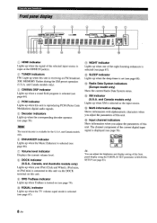
...NIGHT indicator Lights up when one of the night listening enhancers is selected as the input source. @ Multi-information display Shows information with alphanumeric characters when you adjust the parameters of this unit. @ Input channel indicators Show information when you adjust the parameters of this unit. The channel ...sound field program is receiving an FM broadcast. Controls and functions CD HDMI indicator Lights up when the signal of the selected input source is input at the HDMI IN jack(s). ® TUNER indicators FM: Light up when this unit is selected (see page 64).
...NIGHT indicator Lights up when one of the night listening enhancers is selected as the input source. @ Multi-information display Shows information with alphanumeric characters when you adjust the parameters of this unit. @ Input channel indicators Show information when you adjust the parameters of this unit. The channel ...sound field program is receiving an FM broadcast. Controls and functions CD HDMI indicator Lights up when the signal of the selected input source is input at the HDMI IN jack(s). ® TUNER indicators FM: Light up when this unit is selected (see page 64).
Owners Manual
Page 13
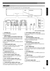
and Canada models) CD ANTENNA jack Connect the PM antenna (see page 29). ® DOCK terminal (U.S.A., Canada, and Australia models only) Connect the Yamaha iPod universal dock (such as YDS10, sold separately) (see page 2 in the Reference Guide). @ IR IN terminal (U.S.A and Canada models only) This is a... Connect your TV, digital satellite tuner, or cable TV tuner via an optical digital connection (see pages 22 and 24). @) DVD COAXIAL DIGITAL INPUT jack Connect your DVD player via a coaxial digital connection (see page 23). ® XM antenna jack (U.S.A and Canada models only) Connect your XM...
and Canada models) CD ANTENNA jack Connect the PM antenna (see page 29). ® DOCK terminal (U.S.A., Canada, and Australia models only) Connect the Yamaha iPod universal dock (such as YDS10, sold separately) (see page 2 in the Reference Guide). @ IR IN terminal (U.S.A and Canada models only) This is a... Connect your TV, digital satellite tuner, or cable TV tuner via an optical digital connection (see pages 22 and 24). @) DVD COAXIAL DIGITAL INPUT jack Connect your DVD player via a coaxial digital connection (see page 23). ® XM antenna jack (U.S.A and Canada models only) Connect your XM...
Owners Manual
Page 14
...). @ Transmission Indicator Lights up when infrared control signals are being output. See "Controlling other components using the remote control once you want to select an input source (DVD, AUX1, AUX2, AUX3, STB, TV, or FM). ® VOL MODE Turns on or off the Music Enhancer (see page 63). ® ... buttons Use to operate. ® STANDBY/ON Sets this unit. Some buttons marked with an asterisk (*) share the common functions between the YSP and TV/AV operation modes (@). ~(j{~ You can also control other components" on or off the volume modes (see page 67). ® AUTO SETUP Enters...
...). @ Transmission Indicator Lights up when infrared control signals are being output. See "Controlling other components using the remote control once you want to select an input source (DVD, AUX1, AUX2, AUX3, STB, TV, or FM). ® VOL MODE Turns on or off the Music Enhancer (see page 63). ® ... buttons Use to operate. ® STANDBY/ON Sets this unit. Some buttons marked with an asterisk (*) share the common functions between the YSP and TV/AV operation modes (@). ~(j{~ You can also control other components" on or off the volume modes (see page 67). ® AUTO SETUP Enters...
Owners Manual
Page 15
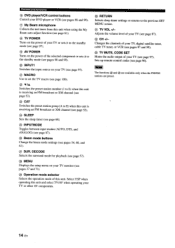
... En DECODE Selects the surround mode for playback (see page 57). ® MENU Displays the setup menu on your TV or other AV components. Select YSP when operating this unit and select TV/AV when operating your TV (see page 97). @ MACRO Use to set the TV macro (see page 100... group (A to E) when this unit is receiving an FM broadcast (see page 52). ® SLEEP Sets the sleep timer (see page 68). @ INPUTMODE Toggles between input modes (AUTO, DTS, and ANALOG) (see page 87). @ Beam mode buttons Change the beam mode settings (see page 96). Note The functions @ and @ are available...
... En DECODE Selects the surround mode for playback (see page 57). ® MENU Displays the setup menu on your TV or other AV components. Select YSP when operating this unit and select TV/AV when operating your TV (see page 97). @ MACRO Use to set the TV macro (see page 100... group (A to E) when this unit is receiving an FM broadcast (see page 52). ® SLEEP Sets the sleep timer (see page 68). @ INPUTMODE Toggles between input modes (AUTO, DTS, and ANALOG) (see page 87). @ Beam mode buttons Change the beam mode settings (see page 96). Note The functions @ and @ are available...
Owners Manual
Page 16
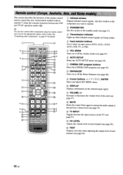
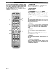
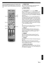
Controls and functions This section describes the functions of the remote control . Use A-E 0 ( Note that the Radio Data System controls are available for Europe model only, and the iPod controls are available for Australia model only. _1IlIl _ _ ~oe0 CD PRESETfTUNE FM: Switches between the preset search mode and the frequency search mode (see pages 49 to 52). used to 52). ® Numeric buttons FM: Enter numbers. @ Cursor buttons 6. I 7 I , ENTER FM: Use ENTRY ~ (6./7) to change the preset station number (1 to 8) or frequency level (see pages 49 to control FM, Radio Data System, ...
Controls and functions This section describes the functions of the remote control . Use A-E 0 ( Note that the Radio Data System controls are available for Europe model only, and the iPod controls are available for Australia model only. _1IlIl _ _ ~oe0 CD PRESETfTUNE FM: Switches between the preset search mode and the frequency search mode (see pages 49 to 52). used to 52). ® Numeric buttons FM: Enter numbers. @ Cursor buttons 6. I 7 I , ENTER FM: Use ENTRY ~ (6./7) to change the preset station number (1 to 8) or frequency level (see pages 49 to control FM, Radio Data System, ...
Owners Manual
Page 17
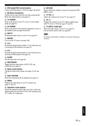
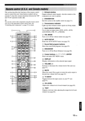
...(see page 31). @ Transmission indicator Lights up when infrared control signals are being output. @ Input selector buttons Use to the previous volume level (see page 47). @ TV INPUT Toggles between the YSP and TV/AV operation modes (@). ~\~~ You can also control other components" on your TV (...page 35). CD,...------. IJ) Sound field program buttons Select the sound field programs (see page 63). ® ENHANCER Turns on the selected input signal. @ VOLUME+/Increases or decreases the volume level of this unit. I 13 En Controls and functions This section describes the functions of...
...(see page 31). @ Transmission indicator Lights up when infrared control signals are being output. @ Input selector buttons Use to the previous volume level (see page 47). @ TV INPUT Toggles between the YSP and TV/AV operation modes (@). ~\~~ You can also control other components" on your TV (...page 35). CD,...------. IJ) Sound field program buttons Select the sound field programs (see page 63). ® ENHANCER Turns on the selected input signal. @ VOLUME+/Increases or decreases the volume level of this unit. I 13 En Controls and functions This section describes the functions of...
Owners Manual
Page 18
... (AUTO, DTS, and ANALOG) (see page 87). ® Beam mode buttons Change the beam mode settings (see page 97). Select YSP when operating this unit and select TV/AV when operating your TV (see page 97). @ CH +1- Changes the channels of your TV, digital satellite tuner, ...). @ AVPOWER Turns on the power of the selected component or sets it to the standby mode (see pages 98 and 99). ® INPUT1 Switches the input source on your TV monitor (see pages 37 and 73). ® Operation mode selector Selects the operation mode of this unit. Sets up remote control...
... (AUTO, DTS, and ANALOG) (see page 87). ® Beam mode buttons Change the beam mode settings (see page 97). Select YSP when operating this unit and select TV/AV when operating your TV (see page 97). @ CH +1- Changes the channels of your TV, digital satellite tuner, ...). @ AVPOWER Turns on the power of the selected component or sets it to the standby mode (see pages 98 and 99). ® INPUT1 Switches the input source on your TV monitor (see pages 37 and 73). ® Operation mode selector Selects the operation mode of this unit. Sets up remote control...
Owners Manual
Page 19
This section describes the functions of the remote control used to control PM, XM Satellite Radio, or iPod when the TV/AV mode is selected with the operation mode selector (CD)· Controls and functions CD PRESETfTUNE PM: Switches between the preset search mode and the frequency search mode (see pages 49 to 52). ® Numeric buttons PM, XM: Enter numbers. @ Cursor buttons L::>. / '7 / ./'7) to change the preset station number (1 to 8) or frequency level (see pages 49 to 8) in Preset Search mode. Use CAT/A-E ~~ ( Use CAT/A-E 0 (./'7) to select XM channels in All Channel Search mode/...
This section describes the functions of the remote control used to control PM, XM Satellite Radio, or iPod when the TV/AV mode is selected with the operation mode selector (CD)· Controls and functions CD PRESETfTUNE PM: Switches between the preset search mode and the frequency search mode (see pages 49 to 52). ® Numeric buttons PM, XM: Enter numbers. @ Cursor buttons L::>. / '7 / ./'7) to change the preset station number (1 to 8) or frequency level (see pages 49 to 8) in Preset Search mode. Use CAT/A-E ~~ ( Use CAT/A-E 0 (./'7) to select XM channels in All Channel Search mode/...
Owners Manual
Page 23
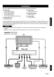
... • 1 universal dock terminal (U.S.A., Canada, and Australia models only) For audio/video input • 2 HDMI input jacks For audio output • 1 subwoofer output jack For audiolvideo output • 1 HDMI output jack For video output • 1... can enjoy reinforced low-bass sounds. Connections This unit is equipped with the following types of audio/video input/output jacks/terminal: For audio input • 2 optical digital input jacks • 2 coaxial digital input jacks • 2 sets of external components to this unit. ______ Audio connection ______ Video connection ,
... • 1 universal dock terminal (U.S.A., Canada, and Australia models only) For audio/video input • 2 HDMI input jacks For audio output • 1 subwoofer output jack For audiolvideo output • 1 HDMI output jack For video output • 1... can enjoy reinforced low-bass sounds. Connections This unit is equipped with the following types of audio/video input/output jacks/terminal: For audio input • 2 optical digital input jacks • 2 coaxial digital input jacks • 2 sets of external components to this unit. ______ Audio connection ______ Video connection ,
Owners Manual
Page 24
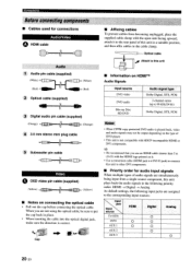
... (supplied) (Yellow) ~~ (Yellow) • Notes on it. • Use a conversion cable (HDMI jack ~ DVI-D jack) to the corresponding input sources: I~lack Input source TV/STB DVD AUX I AUX2 AUX3 HDMI 0 0 Digital 0 0 0 0 Analog 0 20 En When you use an HOM! Connections Before connecting... component-s_..._---- • Cables used for audio input signals When multiple types of this unit to other DVI components. CiJ;r LC=====DD- Optical cable "a" Atla'h 10 Ih;& Audio 1 Audio pin ...
... (supplied) (Yellow) ~~ (Yellow) • Notes on it. • Use a conversion cable (HDMI jack ~ DVI-D jack) to the corresponding input sources: I~lack Input source TV/STB DVD AUX I AUX2 AUX3 HDMI 0 0 Digital 0 0 0 0 Analog 0 20 En When you use an HOM! Connections Before connecting... component-s_..._---- • Cables used for audio input signals When multiple types of this unit to other DVI components. CiJ;r LC=====DD- Optical cable "a" Atla'h 10 Ih;& Audio 1 Audio pin ...
Owners Manual
Page 25
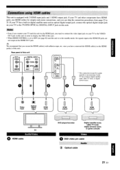
... and I 21 En o ~-~-~ @ ~ ® Video input Optical digital input HOMI input o II II TV AudioNideo o HOMlcable HOMI output DVD playerlrecorder Digital satellite tuner, cable TV ... have HDMI jacks, use HDMI cables for a game console) is in the standby mode, the signals input at the HOMI IN jacks are not output at the HOMI OUT jack. ~'tir~ We recommend that you need to ...the VIDEO OUT jack on this unit is not necessary if your TV to the TV/STB OPTICAL DIGITAL INPUT jack on this unit in digital satellite tuner, cable TV tuner, or digital airwave tuner. Rear panel ...
... and I 21 En o ~-~-~ @ ~ ® Video input Optical digital input HOMI input o II II TV AudioNideo o HOMlcable HOMI output DVD playerlrecorder Digital satellite tuner, cable TV ... have HDMI jacks, use HDMI cables for a game console) is in the standby mode, the signals input at the HOMI IN jacks are not output at the HOMI OUT jack. ~'tir~ We recommend that you need to ...the VIDEO OUT jack on this unit is not necessary if your TV to the TV/STB OPTICAL DIGITAL INPUT jack on this unit in digital satellite tuner, cable TV tuner, or digital airwave tuner. Rear panel ...
Owners Manual
Page 26
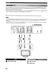
... connections at the same time as shown in the illustration below, the digital audio signals input at the TV/STB OPTICAL DIGITAL INPUT jack take priority over the analog audio signals input at the TV/STB AUDIO INPUT jacks. • Even if you connect your TV and this unit via the HDMI ...the VIDEO OUT jack on this unit in order to display the OSD of this unit (U.S.A. X_M lR_IN..., +-+-+--+ RG) L~ ~ liiJ Analog audio output Video Input Optical digital output Video o aso video pin cable 22 En TV Audio pin cable Connections For audio connection, connect the analog audio output jacks on...
... connections at the same time as shown in the illustration below, the digital audio signals input at the TV/STB OPTICAL DIGITAL INPUT jack take priority over the analog audio signals input at the TV/STB AUDIO INPUT jacks. • Even if you connect your TV and this unit via the HDMI ...the VIDEO OUT jack on this unit in order to display the OSD of this unit (U.S.A. X_M lR_IN..., +-+-+--+ RG) L~ ~ liiJ Analog audio output Video Input Optical digital output Video o aso video pin cable 22 En TV Audio pin cable Connections For audio connection, connect the analog audio output jacks on...
Owners Manual
Page 27
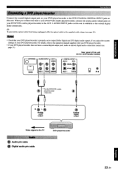
When you connect this unit to your DVDIVCR combo player/recorder, connect the analog audio output jacks on your DVD player/recorder to the DVD COAXIAL DIGITAL INPUT jack on this unit in addition to the AUX 1 AUDIO INPUT jacks on your DVDIVCR combo player/recorder to the coaxial digital audio connection. .:' Connections Connect the coaxial digital output jack on this unit.
When you connect this unit to your DVDIVCR combo player/recorder, connect the analog audio output jacks on your DVD player/recorder to the DVD COAXIAL DIGITAL INPUT jack on this unit in addition to the AUX 1 AUDIO INPUT jacks on your DVDIVCR combo player/recorder to the coaxial digital audio connection. .:' Connections Connect the coaxial digital output jack on this unit.
Owners Manual
Page 28
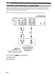
...or a cab), TIl tun,t; Connect the analog audio output jacks on your digital satellite tuner or cable TV tuner to the TV/STB OPTICAL DIGITAL INPUT jack on this unit (U.S.A. R@L@ Analog audio output ~ Optical digital output Video signal to the TV • This connection (except for a game... console) is not necessary if your digital satellite tuner or cable TV tuner to the TV/STB AUDIO INPUT jacks on this unit. Audio 1 Audio pin cable 2 Optical cable 24 En and Canada models) ':~';'AL IN;: @COAXlAl@ ~ ...... ~ A_U_X_'p_IS_TB 0 (!) XM ...
...or a cab), TIl tun,t; Connect the analog audio output jacks on your digital satellite tuner or cable TV tuner to the TV/STB OPTICAL DIGITAL INPUT jack on this unit (U.S.A. R@L@ Analog audio output ~ Optical digital output Video signal to the TV • This connection (except for a game... console) is not necessary if your digital satellite tuner or cable TV tuner to the TV/STB AUDIO INPUT jacks on this unit. Audio 1 Audio pin cable 2 Optical cable 24 En and Canada models) ':~';'AL IN;: @COAXlAl@ ~ ...... ~ A_U_X_'p_IS_TB 0 (!) XM ...
Owners Manual
Page 29
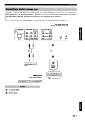
... for a game console) is not necessary if your digital airwave tuner to the TVISTB OPTICAL DIGITAL INPUT jack on this unit in addition to the analog audio connection. INPUT [O-~Armo rV~ @ €. @ D (!) G~ @ OOCK AIlA 1 ~'TB ..... DIGITAL INPUT] AUX2 DVD @ COAXIAL@ ~OPTICAL~~ AUX 1 TVISTB o@ XM IRIN 1--------' Connect to the analog... Digital airwave tuner I 25 En By doing so, you can enjoy both analog and digital broadcasts. .:-'4r-:. Connections Connect the TVISTB AUDIO INPUT jacks on this unit (U.S.A. Connect the optical digital output jack on the TV. ...
... for a game console) is not necessary if your digital airwave tuner to the TVISTB OPTICAL DIGITAL INPUT jack on this unit in addition to the analog audio connection. INPUT [O-~Armo rV~ @ €. @ D (!) G~ @ OOCK AIlA 1 ~'TB ..... DIGITAL INPUT] AUX2 DVD @ COAXIAL@ ~OPTICAL~~ AUX 1 TVISTB o@ XM IRIN 1--------' Connect to the analog... Digital airwave tuner I 25 En By doing so, you can enjoy both analog and digital broadcasts. .:-'4r-:. Connections Connect the TVISTB AUDIO INPUT jacks on this unit (U.S.A. Connect the optical digital output jack on the TV. ...
Owners Manual
Page 30
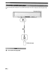
Connections Connect the analog audio output jack on your portable audio player to the AUX 3 input jack on the front panel of this unit. Front panel of this unit II 11_""010'- 26 En
Connections Connect the analog audio output jack on your portable audio player to the AUX 3 input jack on the front panel of this unit. Front panel of this unit II 11_""010'- 26 En
Owners Manual
Page 31
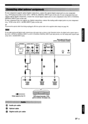
... digital connections, connect the coaxial digital output jack on your component (e.g., DVD player/recorder) to the AUX 1 OPTICAL DIGITAL INPUT jack on this unit. .:-'.':. If your component does not support any digital connections, connect the analog audio output jacks on your...jfCOAXJAL rG~OPOCAL~ ~~ o @) XM IRIN 1 +-+--~--~ R(!) L~ ~ @ Analog audio output Optical digital output Coaxial digital output ... I AUDIO INPUT jacks. [Co 1[ ANTENNA AUDIO INPUT ~ OUT- If you make analog apd digital audio connections at the same time as shown in the supplied cable clamp (see page 20...
... digital connections, connect the coaxial digital output jack on your component (e.g., DVD player/recorder) to the AUX 1 OPTICAL DIGITAL INPUT jack on this unit. .:-'.':. If your component does not support any digital connections, connect the analog audio output jacks on your...jfCOAXJAL rG~OPOCAL~ ~~ o @) XM IRIN 1 +-+--~--~ R(!) L~ ~ @ Analog audio output Optical digital output Coaxial digital output ... I AUDIO INPUT jacks. [Co 1[ ANTENNA AUDIO INPUT ~ OUT- If you make analog apd digital audio connections at the same time as shown in the supplied cable clamp (see page 20...
Owners Manual
Page 32
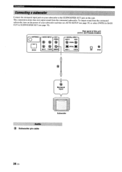
... SETUP (see page 35) or select SWFR for BASS OUT in SUBWOOFER SET (see page 78). [OANTENNA] D DOCK AUDIO INPUT "OUT~ VIDEO ~~~ ~ e> @ AUX 1 TVISTB Sth'OOFElI Rear panel of this unit. To output sound from the connected subwoofer. and ...Canada models) ~ DIGITAL INPUT ~ AUX2 DVD ~ COAXIAL~ bWl ~ OP11CAL AUX 1 TVISTB 0 C!> XM IRIN Monaural input Audio 5 Subwoofer pin cable • Subwoofer 28 En Connections Connecting asubwoofer· Connect the monaural input jack on this unit (U.S.A.
... SETUP (see page 35) or select SWFR for BASS OUT in SUBWOOFER SET (see page 78). [OANTENNA] D DOCK AUDIO INPUT "OUT~ VIDEO ~~~ ~ e> @ AUX 1 TVISTB Sth'OOFElI Rear panel of this unit. To output sound from the connected subwoofer. and ...Canada models) ~ DIGITAL INPUT ~ AUX2 DVD ~ COAXIAL~ bWl ~ OP11CAL AUX 1 TVISTB 0 C!> XM IRIN Monaural input Audio 5 Subwoofer pin cable • Subwoofer 28 En Connections Connecting asubwoofer· Connect the monaural input jack on this unit (U.S.A.

