
Owner's Manual
Page 1
UB YSP-800 Digital Sound Projector OWNER'S MANUAL
UB YSP-800 Digital Sound Projector OWNER'S MANUAL
Owner's Manual
Page 3
.../or another product use the product. 2. This equipment generates/uses radio frequencies and, if not installed and used . In the case of other electronic devices. ii Cable/s supplied with the requirements listed in all installation instructions. Utilize power outlets that lets the sound come through loud and clear without affecting your equipment by YAMAHA may cause interference harmful to the operation of radio or TV interference...
.../or another product use the product. 2. This equipment generates/uses radio frequencies and, if not installed and used . In the case of other electronic devices. ii Cable/s supplied with the requirements listed in all installation instructions. Utilize power outlets that lets the sound come through loud and clear without affecting your equipment by YAMAHA may cause interference harmful to the operation of radio or TV interference...
Owner's Manual
Page 4
..., as it may be held responsible for cooling. 19 Install this manual carefully. Contact qualified YAMAHA service personnel when any damage resulting from use this might damage the finish. Retain this appliance, it in the space below. Note that neither core is called the standby mode. CAUTION: READ THIS BEFORE OPERATING THIS UNIT. away from direct sunlight, heat sources, vibration...
..., as it may be held responsible for cooling. 19 Install this manual carefully. Contact qualified YAMAHA service personnel when any damage resulting from use this might damage the finish. Retain this appliance, it in the space below. Note that neither core is called the standby mode. CAUTION: READ THIS BEFORE OPERATING THIS UNIT. away from direct sunlight, heat sources, vibration...

Owner's Manual
Page 5
... OPERATION BASIC SETUP 57 MANUAL SETUP 63 Using MANUAL SETUP 64 BEAM MENU 65 SOUND MENU 69 INPUT MENU 71 DISPLAY MENU 73 ADJUSTING SYSTEM PARAMETERS ...........75 Setting the maximum volume level 75 Protecting the current settings 76 Initializing the current settings 77 Adjusting the audio balance 78 SELECTING THE INPUT MODE 81 REMOTE CONTROL FEATURES 82 Setting remote control codes 82 Controlling other components 83 Using the TV macro 85 ADDITIONAL INFORMATION TROUBLESHOOTING 87 GLOSSARY 90 Audio formats 90 Audio information...
... OPERATION BASIC SETUP 57 MANUAL SETUP 63 Using MANUAL SETUP 64 BEAM MENU 65 SOUND MENU 69 INPUT MENU 71 DISPLAY MENU 73 ADJUSTING SYSTEM PARAMETERS ...........75 Setting the maximum volume level 75 Protecting the current settings 76 Initializing the current settings 77 Adjusting the audio balance 78 SELECTING THE INPUT MODE 81 REMOTE CONTROL FEATURES 82 Setting remote control codes 82 Controlling other components 83 Using the TV macro 85 ADDITIONAL INFORMATION TROUBLESHOOTING 87 GLOSSARY 90 Audio formats 90 Audio information...
Owner's Manual
Page 6
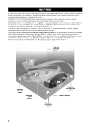
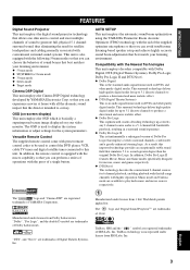
YAMAHA YSP-800 Digital Sound Projector challenges this unit to -life 5.1 channel surround sound that your listening room will give you the same kind of surround sound experience as if there are reflected off the walls of your local movie theater. The YSP-800 projects sound beams containing surround sound information for the front right (R), front left (L), surround right (SR) and surround left speaker 2 This slimline unit does away with the need for complicated wiring and installation worries...
YAMAHA YSP-800 Digital Sound Projector challenges this unit to -life 5.1 channel surround sound that your listening room will give you the same kind of surround sound experience as if there are reflected off the walls of your local movie theater. The YSP-800 projects sound beams containing surround sound information for the front right (R), front left (L), surround right (SR) and surround left speaker 2 This slimline unit does away with the need for complicated wiring and installation worries...
Owner's Manual
Page 7
... surround technology deliver high-quality digital audio for 6 channel playback, enabling playback with the full-range channels with preset remote control codes to play back music and movie sources respectively. "Dolby", "Pro Logic", and the double-D symbol are trademarks of a single button. The ' ' logo and 'Digital Sound Projector™' are available to be used on your listening environment. English 3 Versatile Remote Control The supplied remote control come with higher separation. Compatibility...
... surround technology deliver high-quality digital audio for 6 channel playback, enabling playback with the full-range channels with preset remote control codes to play back music and movie sources respectively. "Dolby", "Pro Logic", and the double-D symbol are trademarks of a single button. The ' ' logo and 'Digital Sound Projector™' are available to be used on your listening environment. English 3 Versatile Remote Control The supplied remote control come with higher separation. Compatibility...
Owner's Manual
Page 8
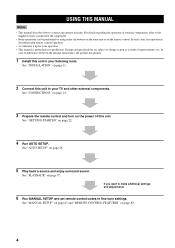
... and enjoy surround sound. See "GETTING STARTED" on page 82. 4 See "MANUAL SETUP" on page 63 and "REMOTE CONTROL FEATURES" on page 22. 4 Run AUTO SETUP. For details regarding the operation of this unit in part as a result of differences between the manual and product, the product has priority. 1 Install this unit. See "INSTALLATION" on the power of external components, refer to the supplied owner's manual for...
... and enjoy surround sound. See "GETTING STARTED" on page 82. 4 See "MANUAL SETUP" on page 63 and "REMOTE CONTROL FEATURES" on page 22. 4 Run AUTO SETUP. For details regarding the operation of this unit in part as a result of differences between the manual and product, the product has priority. 1 Install this unit. See "INSTALLATION" on the power of external components, refer to the supplied owner's manual for...
Owner's Manual
Page 13
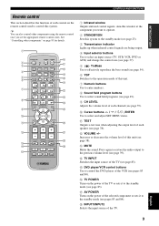
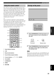
...). D TV INPUT Switches the input source of this unit. 7 Numeric buttons Use to enter numbers. 8 Sound field program buttons Use to select sound field programs (see page 49). 9 CH LEVEL Adjusts the volume level of each channel (see page 79). 0 Cursor buttons / / / , ENTER Use to select and adjust SET MENU items. A TEST Outputs a test tone when adjusting the output level of each control on the power of the selected component or sets it to the standby mode (see...
...). D TV INPUT Switches the input source of this unit. 7 Numeric buttons Use to enter numbers. 8 Sound field program buttons Use to select sound field programs (see page 49). 9 CH LEVEL Adjusts the volume level of each channel (see page 79). 0 Cursor buttons / / / , ENTER Use to select and adjust SET MENU items. A TEST Outputs a test tone when adjusting the output level of each control on the power of the selected component or sets it to the standby mode (see...
Owner's Manual
Page 24
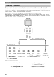
... DIGITAL INPUT SYSTEM CONNECTOR System connector cable (supplied with the YAMAHA subwoofer with a SYSTEM CONNECTOR jack, connect it to the SYSTEM CONNECTOR jack on this unit. Subwoofer Monaural System input connector Rear panel of the subwoofer. If the subwoofer is connected to the SYSTEM CONNECTOR jack (U.S.A. CONNECTIONS Connecting a subwoofer To connect a subwoofer, connect the monaural input jack on your subwoofer and then run AUTO SETUP (see page 70). and Canada models only) VCR TV/STB SUBWOOFER VIDEO AUDIO INPUT (U.S.A. Connecting to this unit, turn on the power...
... DIGITAL INPUT SYSTEM CONNECTOR System connector cable (supplied with the YAMAHA subwoofer with a SYSTEM CONNECTOR jack, connect it to the SYSTEM CONNECTOR jack on this unit. Subwoofer Monaural System input connector Rear panel of the subwoofer. If the subwoofer is connected to the SYSTEM CONNECTOR jack (U.S.A. CONNECTIONS Connecting a subwoofer To connect a subwoofer, connect the monaural input jack on your subwoofer and then run AUTO SETUP (see page 70). and Canada models only) VCR TV/STB SUBWOOFER VIDEO AUDIO INPUT (U.S.A. Connecting to this unit, turn on the power...
Owner's Manual
Page 27
... CH LEVEL CINEMA DSP MENU 5 TEST ENTER RETURN 6 7 8 9 1 Input selector buttons 2 YSP 3 Beam mode buttons 4 Sound field program buttons 5 Cursor buttons / / / , ENTER 6 VOL MODE 7 SURROUND 8 MENU 9 RETURN Turning on the power VOLUME + STANDBY/ON STANDBY/ON POWER POWER AV TV DVD AUX VCR INPUT1 STB TV INPUT2 TV MACRO 1 Press STANDBY/ON on the front panel or on the remote control to turn on the remote control are operational only after you press YSP to switch...
... CH LEVEL CINEMA DSP MENU 5 TEST ENTER RETURN 6 7 8 9 1 Input selector buttons 2 YSP 3 Beam mode buttons 4 Sound field program buttons 5 Cursor buttons / / / , ENTER 6 VOL MODE 7 SURROUND 8 MENU 9 RETURN Turning on the power VOLUME + STANDBY/ON STANDBY/ON POWER POWER AV TV DVD AUX VCR INPUT1 STB TV INPUT2 TV MACRO 1 Press STANDBY/ON on the front panel or on the remote control to turn on the remote control are operational only after you press YSP to switch...
Owner's Manual
Page 31
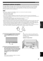
... crossover/high cut frequency controls is placed in a proper location and that the optimizer microphone is connected to this unit. • Make sure that there are seated in your normal listening position. Do not place it away from the center height of using MANUAL SETUP (see page 63) once the AUTO SETUP procedure is completed. • If a subwoofer with adjustable volume and crossover/high cut frequency...
... crossover/high cut frequency controls is placed in a proper location and that the optimizer microphone is connected to this unit. • Make sure that there are seated in your normal listening position. Do not place it away from the center height of using MANUAL SETUP (see page 63) once the AUTO SETUP procedure is completed. • If a subwoofer with adjustable volume and crossover/high cut frequency...

Owner's Manual
Page 33
...; If the AUTO SETUP procedure stops and an error message appears on the screen, see "Error messages for AUTO SETUP" on page 11. The SET MENU screen appears on the remote control. • To resume cursor button operations after changing the control area by the AUTO SETUP procedure (see page 34). STANDBY/ON Front panel or Remote control ENTER ENTER 2 Press YSP on the remote control to switch to the operation mode of sound beams...
...; If the AUTO SETUP procedure stops and an error message appears on the screen, see "Error messages for AUTO SETUP" on page 11. The SET MENU screen appears on the remote control. • To resume cursor button operations after changing the control area by the AUTO SETUP procedure (see page 34). STANDBY/ON Front panel or Remote control ENTER ENTER 2 Press YSP on the remote control to switch to the operation mode of sound beams...

Owner's Manual
Page 42
... Adjusting the volume INPUT VOLUME + STANDBY/ON VOLUME CH TV VOL MUTE TV INPUT TV MUTE Press VOLUME +/- y • If the output volume is displayed. 3 If necessary, turn down the volume of the volume level increases or decreases each time you press VOLUME +/-. • You can continuously increase or decrease the volume level if you can use the remote control supplied with this unit. on the front panel or on the remote control to the owner's manual supplied...
... Adjusting the volume INPUT VOLUME + STANDBY/ON VOLUME CH TV VOL MUTE TV INPUT TV MUTE Press VOLUME +/- y • If the output volume is displayed. 3 If necessary, turn down the volume of the volume level increases or decreases each time you press VOLUME +/-. • You can continuously increase or decrease the volume level if you can use the remote control supplied with this unit. on the front panel or on the remote control to the owner's manual supplied...

Owner's Manual
Page 44
... stereo, stereo plus 3 beam mode for INSTALLED POSITION in MANUAL SETUP (see page 65) AUTO SETUP BASIC SETUP MANUAL SETUP Beam mode INSTALLING (see page 30) Parallel to Wall Angle to Wall or corner INSTALLED POSITION (see page 59) CORNER RIGHT or CORNER LEFT Other settings INSTALLED POSITION (see page 59) • If you selected Angle to suit the input source of this unit using the beam mode buttons on the remote control (STEREO...
... stereo, stereo plus 3 beam mode for INSTALLED POSITION in MANUAL SETUP (see page 65) AUTO SETUP BASIC SETUP MANUAL SETUP Beam mode INSTALLING (see page 30) Parallel to Wall Angle to Wall or corner INSTALLED POSITION (see page 59) CORNER RIGHT or CORNER LEFT Other settings INSTALLED POSITION (see page 59) • If you selected Angle to suit the input source of this unit using the beam mode buttons on the remote control (STEREO...

Owner's Manual
Page 70
... wall A)SETTING PARAMETERS 3/3 12.0m p p p [ ]/[ ]:Up/Down[ ]/[ ]:Sel [ENTER]:Return Note When you set the INSTALLED POSITION parameter in BASIC SETUP (see page 59) or MANUAL SETUP (see page 40), some speaker positions may not be output from the left and right speakers. When using the stereo plus 3 beam mode, set to move the direction of this unit: 2.0 m to 9.0 m (6.5 ft to manually adjust the various speaker beam angles. Adjust...
... wall A)SETTING PARAMETERS 3/3 12.0m p p p [ ]/[ ]:Up/Down[ ]/[ ]:Sel [ENTER]:Return Note When you set the INSTALLED POSITION parameter in BASIC SETUP (see page 59) or MANUAL SETUP (see page 40), some speaker positions may not be output from the left and right speakers. When using the stereo plus 3 beam mode, set to move the direction of this unit: 2.0 m to 9.0 m (6.5 ft to manually adjust the various speaker beam angles. Adjust...
Owner's Manual
Page 74
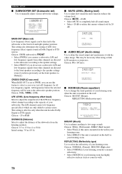
... BASS OUT is mounted on the wall. Choices: 80Hz, 100Hz, 120Hz LFE LEVEL (Low-frequency effect level) Select to adjust the output level of the LFE (low-frequency effect) channel according to adjust the distance of your listening room has highly reflective surfaces such as concrete walls. 70 REFLECTING (Reflectivity type) Use to the subwoofer speaker position. LFE and low-frequency signals from the listening position. MANUAL SETUP ■ SUBWOOFER SET (Subwoofer set the...
... BASS OUT is mounted on the wall. Choices: 80Hz, 100Hz, 120Hz LFE LEVEL (Low-frequency effect level) Select to adjust the output level of the LFE (low-frequency effect) channel according to adjust the distance of your listening room has highly reflective surfaces such as concrete walls. 70 REFLECTING (Reflectivity type) Use to the subwoofer speaker position. LFE and low-frequency signals from the listening position. MANUAL SETUP ■ SUBWOOFER SET (Subwoofer set the...
Owner's Manual
Page 91
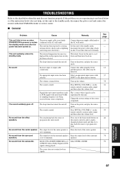
.... TROUBLESHOOTING TROUBLESHOOTING Refer to the chart below does not help, set to minimum. Play a source whose signals can be defective. speakers. You are experiencing is turned down and then turn on the remote control to the AC wall outlet. The sound is not firmly connected to resume audio output and then adjust the volume level. on the power, and play the source again. The power supply cable is muted. No sound from the center speaker. Connect...
.... TROUBLESHOOTING TROUBLESHOOTING Refer to the chart below does not help, set to minimum. Play a source whose signals can be defective. speakers. You are experiencing is turned down and then turn on the remote control to the AC wall outlet. The sound is not firmly connected to resume audio output and then adjust the volume level. on the power, and play the source again. The power supply cable is muted. No sound from the center speaker. Connect...

Owner's Manual
Page 94
... and right channels, 1 center channel, and 2 surround left , right and center channels, 2 surround channels, plus an LFE 0.1 channel as 0.1 because it only enforces a low frequency range compared to minimum volume) reproduced by adding the surround back channel to 120 Hz. Music mode for playing music sources and Cinema mode for the surround speakers, more accurate moving sound effects and directionality. ■ DTS (Digital Theater Systems) Digital Surround DTS digital surround was developed to decode vast numbers of existing...
... and right channels, 1 center channel, and 2 surround left , right and center channels, 2 surround channels, plus an LFE 0.1 channel as 0.1 because it only enforces a low frequency range compared to minimum volume) reproduced by adding the surround back channel to 120 Hz. Music mode for playing music sources and Cinema mode for the surround speakers, more accurate moving sound effects and directionality. ■ DTS (Digital Theater Systems) Digital Surround DTS digital surround was developed to decode vast numbers of existing...

Owner's Manual
Page 100
... use a tripod or the supplied cardboard microphone stand to affix the optimizer microphone, try to 50° 2. Installing this unit Install this unit where there are likely to obstruct the path of an optical digital connection) An object, such as furniture Correct Correct Monaural input VCR TV/STB SUBWOOFER VIDEO AUDIO INPUT OUT TV/STB AUX OPTICAL DVD COAXIAL DIGITAL INPUT SYSTEM CONNECTOR Rear panel of sound...
... use a tripod or the supplied cardboard microphone stand to affix the optimizer microphone, try to 50° 2. Installing this unit Install this unit where there are likely to obstruct the path of an optical digital connection) An object, such as furniture Correct Correct Monaural input VCR TV/STB SUBWOOFER VIDEO AUDIO INPUT OUT TV/STB AUX OPTICAL DVD COAXIAL DIGITAL INPUT SYSTEM CONNECTOR Rear panel of sound...
Owner's Manual
Page 101
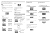
... ;;;[OK] SUB WOOFER CHECK ;;;[NOT IN USE] WILL START in your listening room. See "Error messages for AUTO SETUP" on your TV. CH LEVEL CINEMA DSP MENU TEST ENTER RETURN AUTO SETTING COMPLETED 4. VOLUME CH TV VOL 5 Press YSP on the remote control to switch to adjust the volume level. CH LEVEL CINEMA DSP MENU TEST ENTER RETURN SET MENU . ;MEMORY ;AUTO SETUP ;BASIC SETUP ;MANUAL SETUP [ ]/[ ]:Up/Down [ENTER]:Enter 5 Press / on the remote control to the operation mode of...
... ;;;[OK] SUB WOOFER CHECK ;;;[NOT IN USE] WILL START in your listening room. See "Error messages for AUTO SETUP" on your TV. CH LEVEL CINEMA DSP MENU TEST ENTER RETURN AUTO SETTING COMPLETED 4. VOLUME CH TV VOL 5 Press YSP on the remote control to switch to adjust the volume level. CH LEVEL CINEMA DSP MENU TEST ENTER RETURN SET MENU . ;MEMORY ;AUTO SETUP ;BASIC SETUP ;MANUAL SETUP [ ]/[ ]:Up/Down [ENTER]:Enter 5 Press / on the remote control to the operation mode of...


