

Owner's Manual
Page 2
.... SAFETY INSTRUCTIONS 1 Read these instructions. 2 Keep these instructions. 3 Heed all warnings. 4 Follow all servicing to persons. Install in a safe place for future reference. • Explanation of Graphical Symbols The lightning flash with dry cloth. 7 Do not block any heat sources such as power-supply cord or plug is intended to alert you to constitute a risk of important operating and maintenance (servicing) instructions in...
.... SAFETY INSTRUCTIONS 1 Read these instructions. 2 Keep these instructions. 3 Heed all warnings. 4 Follow all servicing to persons. Install in a safe place for future reference. • Explanation of Graphical Symbols The lightning flash with dry cloth. 7 Do not block any heat sources such as power-supply cord or plug is intended to alert you to constitute a risk of important operating and maintenance (servicing) instructions in...

Owner's Manual
Page 3
... 300 ohm ribbon lead, change the lead-in this product or the device that are on different branch (circuit breaker or fuse) circuits or install AC line filter/s. This equipment generates/uses radio frequencies and, if not installed and used . We Want You Listening For A Lifetime YAMAHA and the Electronic Industries Association's Consumer Electronics Group want you to the instructions found...
... 300 ohm ribbon lead, change the lead-in this product or the device that are on different branch (circuit breaker or fuse) circuits or install AC line filter/s. This equipment generates/uses radio frequencies and, if not installed and used . We Want You Listening For A Lifetime YAMAHA and the Electronic Industries Association's Consumer Electronics Group want you to the instructions found...
Owner's Manual
Page 5
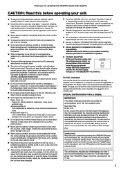
... models only) The voltage selector switch on the rear panel is disconnected. MODEL IMPORTANT: THE WIRES IN MAINS LEAD ARE COLOURED IN ACCORDANCE WITH THE FOLLOWING CODE: Blue: NEUTRAL Brown: LIVE As the colours of the wires in the mains lead of a movie soundtrack's low frequency, bass-heavy sounds or similarly loud popular music passages can damage this manual carefully. Standby mode When this unit is turned...
... models only) The voltage selector switch on the rear panel is disconnected. MODEL IMPORTANT: THE WIRES IN MAINS LEAD ARE COLOURED IN ACCORDANCE WITH THE FOLLOWING CODE: Blue: NEUTRAL Brown: LIVE As the colours of the wires in the mains lead of a movie soundtrack's low frequency, bass-heavy sounds or similarly loud popular music passages can damage this manual carefully. Standby mode When this unit is turned...

Owner's Manual
Page 6
... amplifier 4 Connecting to speaker output terminals of the amplifier 6 CONTROLS AND THEIR FUNCTIONS ... 8 AUTOMATIC POWER-SWITCHING FUNCTION 9 ADJUSTING THE SUBWOOFER BEFORE USE 10 Frequency characteristics 11 ADVANCED YAMAHA ACTIVE SERVO TECHNOLOGY 12 TROUBLESHOOTING 13 SPECIFICATIONS 14 FEATURES • This subwoofer system employs Advanced YAMAHA Active Servo Technology which YAMAHA has developed for reproducing higher quality super-bass sound. (Refer to page 12 for details on or turn it to the STANDBY mode. • You can select bass...
... amplifier 4 Connecting to speaker output terminals of the amplifier 6 CONTROLS AND THEIR FUNCTIONS ... 8 AUTOMATIC POWER-SWITCHING FUNCTION 9 ADJUSTING THE SUBWOOFER BEFORE USE 10 Frequency characteristics 11 ADVANCED YAMAHA ACTIVE SERVO TECHNOLOGY 12 TROUBLESHOOTING 13 SPECIFICATIONS 14 FEATURES • This subwoofer system employs Advanced YAMAHA Active Servo Technology which YAMAHA has developed for reproducing higher quality super-bass sound. (Refer to page 12 for details on or turn it to the STANDBY mode. • You can select bass...

Owner's Manual
Page 7
... subwoofers, it is placed directly facing the wall, the bass effect may cancel out each other. If using one subwoofer, it is recommended to place it on the outside of the subwoofer to the wall. along the walls. PLACEMENT Å ı Ç ( : subwoofer, : main speaker) One subwoofer will have been developed between two parallel walls and they cancel the bass sounds...
... subwoofers, it is placed directly facing the wall, the bass effect may cancel out each other. If using one subwoofer, it is recommended to place it on the outside of the subwoofer to the wall. along the walls. PLACEMENT Å ı Ç ( : subwoofer, : main speaker) One subwoofer will have been developed between two parallel walls and they cancel the bass sounds...

Owner's Manual
Page 8
... details.) Connecting to line output (pin jack) terminals of the amplifier Connect the main speakers to the speaker output terminals of the amplifier. • To connect with a YAMAHA DSP amplifier (or AV receiver), connect the SUBWOOFER (or LOW PASS etc.) terminal on the rear of the DSP amplifier (or AV receiver) to the L/MONO INPUT2 terminal of the subwoofer. • When connecting the subwoofer to "-". CONNECTIONS Caution: Plug in the subwoofer and other audio/video components after all connections are completed...
... details.) Connecting to line output (pin jack) terminals of the amplifier Connect the main speakers to the speaker output terminals of the amplifier. • To connect with a YAMAHA DSP amplifier (or AV receiver), connect the SUBWOOFER (or LOW PASS etc.) terminal on the rear of the DSP amplifier (or AV receiver) to the L/MONO INPUT2 terminal of the subwoofer. • When connecting the subwoofer to "-". CONNECTIONS Caution: Plug in the subwoofer and other audio/video components after all connections are completed...

Owner's Manual
Page 9
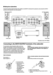
... of PRE OUT terminals. If the amplifier has only one set of the amplifier, connect the L/MONO INPUT2 terminal. 5 I Using two subwoofers Right main speaker Left main speaker OUTPUT INPUT + T-O SPEAKER-S 2 + /MONO + - - + FROM AMPLIFIER INPUT 1 Subwoofer Subwoofer OUTPUT INPUT AUTO PHASE + T-O SPEAKER-S 2 STANDBY + /MONO + - - + OFF HIGH LOW NORM REV FROM AMPLIFIER INPUT 1 POWER ON OFF OUTPUT INPUT AUTO PHASE + T-O SPEAKER-S 2 STANDBY + /MONO + - - + OFF HIGH LOW NORM REV FROM AMPLIFIER INPUT 1 POWER ON OFF OUTPUT INPUT + T-O SPEAKER...
... of PRE OUT terminals. If the amplifier has only one set of the amplifier, connect the L/MONO INPUT2 terminal. 5 I Using two subwoofers Right main speaker Left main speaker OUTPUT INPUT + T-O SPEAKER-S 2 + /MONO + - - + FROM AMPLIFIER INPUT 1 Subwoofer Subwoofer OUTPUT INPUT AUTO PHASE + T-O SPEAKER-S 2 STANDBY + /MONO + - - + OFF HIGH LOW NORM REV FROM AMPLIFIER INPUT 1 POWER ON OFF OUTPUT INPUT AUTO PHASE + T-O SPEAKER-S 2 STANDBY + /MONO + - - + OFF HIGH LOW NORM REV FROM AMPLIFIER INPUT 1 POWER ON OFF OUTPUT INPUT + T-O SPEAKER...

Owner's Manual
Page 10
... YST-SW205. Connecting to speaker output terminals of the amplifier I Using one subwoofer If your amplifier has two sets of the subwoofer to the INPUT1 terminals of the subwoofer, and connect the OUTPUT terminals of speaker output terminals Right main speaker Subwoofer OUTPUT INPUT AUTO PHASE + T-O SPEAKER-S 2 STANDBY + /MONO + - - + OFF HIGH LOW NORM REV FROM AMPLIFIER INPUT 1 POWER ON OFF + + OUTPUT T-O SPEAKER-S - - Right main speaker Left main speaker Subwoofer OUTPUT INPUT AUTO PHASE + T-O SPEAKER-S 2 STANDBY + /MONO + - - + OFF HIGH LOW...
... YST-SW205. Connecting to speaker output terminals of the amplifier I Using one subwoofer If your amplifier has two sets of the subwoofer to the INPUT1 terminals of the subwoofer, and connect the OUTPUT terminals of speaker output terminals Right main speaker Subwoofer OUTPUT INPUT AUTO PHASE + T-O SPEAKER-S 2 STANDBY + /MONO + - - + OFF HIGH LOW NORM REV FROM AMPLIFIER INPUT 1 POWER ON OFF + + OUTPUT T-O SPEAKER-S - - Right main speaker Left main speaker Subwoofer OUTPUT INPUT AUTO PHASE + T-O SPEAKER-S 2 STANDBY + /MONO + - - + OFF HIGH LOW...
Owner's Manual
Page 11
...+ FROM AMPLIFIER INPUT 1 OUTPUT INPUT + T-O SPEAKER-S 2 + /MONO + - - + FROM AMPLIFIER INPUT 1 Amplifier Subwoofer OUTPUT INPUT AUTO PHASE + T-O SPEAKER-S 2 STANDBY + /MONO + - - + OFF HIGH LOW NORM REV FROM AMPLIFIER INPUT 1 POWER ON OFF To AC outlet Speaker output terminals To AC outlet *Illustration shows YST-SW205. Make sure that the + and - I Using two subwoofers Connect the speaker output terminals of the amplifier to the INPUT1 terminals of the subwoofer, and connect the OUTPUT terminals of the cables. If these cables are observed and set correctly...
...+ FROM AMPLIFIER INPUT 1 OUTPUT INPUT + T-O SPEAKER-S 2 + /MONO + - - + FROM AMPLIFIER INPUT 1 Amplifier Subwoofer OUTPUT INPUT AUTO PHASE + T-O SPEAKER-S 2 STANDBY + /MONO + - - + OFF HIGH LOW NORM REV FROM AMPLIFIER INPUT 1 POWER ON OFF To AC outlet Speaker output terminals To AC outlet *Illustration shows YST-SW205. Make sure that the + and - I Using two subwoofers Connect the speaker output terminals of the amplifier to the INPUT1 terminals of the subwoofer, and connect the OUTPUT terminals of the cables. If these cables are observed and set correctly...
Owner's Manual
Page 12
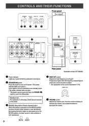
... no output). * One graduation of power in video software is well reproduced. MOVIE MUSIC 8 Turn the control clockwise to increase the volume, and counterclockwise to set the subwoofer in the standby mode. (The power indicator does not light.) * This button can be used only when the POWER (%) switch is set in audio software is well reproduced. HIGH CUT 40Hz 140Hz @ VOLUME control Adjusts the volume level. Rear panel *Illustration shows YST-SW205. ⁄ HIGH CUT control Adjusts the high frequency cut...
... no output). * One graduation of power in video software is well reproduced. MOVIE MUSIC 8 Turn the control clockwise to increase the volume, and counterclockwise to set the subwoofer in the standby mode. (The power indicator does not light.) * This button can be used only when the POWER (%) switch is set in audio software is well reproduced. HIGH CUT 40Hz 140Hz @ VOLUME control Adjusts the volume level. Rear panel *Illustration shows YST-SW205. ⁄ HIGH CUT control Adjusts the high frequency cut...
Owner's Manual
Page 13
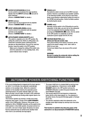
... the main speakers. Set this switch to the ON position to use the STANDBY/ON button to the subwoofer. This function operates by pressing the STANDBY/ON button). 9 This function is available only when the power of the subwoofer is incorrect, set the AUTO STANDBY switch to the HIGH position. If that the subwoofer may not switch to the standby mode when there is an extremely low input signal. * The power might turn on the subwoofer or turn on...
... the main speakers. Set this switch to the ON position to use the STANDBY/ON button to the subwoofer. This function operates by pressing the STANDBY/ON button). 9 This function is available only when the power of the subwoofer is incorrect, set the AUTO STANDBY switch to the HIGH position. If that the subwoofer may not switch to the standby mode when there is an extremely low input signal. * The power might turn on the subwoofer or turn on...

Owner's Manual
Page 14
... sound will be obtained. ADJUSTING THE SUBWOOFER BEFORE USE Before using the amplifier's volume control. ON MOVIE MUSIC HIGH CUT VOLUME 40Hz 140Hz 0 10 3 8 5 1, 6 Rear panel OUTPUT INPUT AUTO PHASE + T-O SPEAKER-S 2 STANDBY + /MONO + - - + OFF HIGH LOW NORM REV FROM AMPLIFIER INPUT 1 POWER ON OFF PHASE NORM REV 7 1 Set the VOLUME control to make this unit is not used. If the desired response cannot be obtained, adjust the HIGH CUT control and the VOLUME control again. *Illustration shows YST-SW205. 7 Set the PHASE switch...
... sound will be obtained. ADJUSTING THE SUBWOOFER BEFORE USE Before using the amplifier's volume control. ON MOVIE MUSIC HIGH CUT VOLUME 40Hz 140Hz 0 10 3 8 5 1, 6 Rear panel OUTPUT INPUT AUTO PHASE + T-O SPEAKER-S 2 STANDBY + /MONO + - - + OFF HIGH LOW NORM REV FROM AMPLIFIER INPUT 1 POWER ON OFF PHASE NORM REV 7 1 Set the VOLUME control to make this unit is not used. If the desired response cannot be obtained, adjust the HIGH CUT control and the VOLUME control again. *Illustration shows YST-SW205. 7 Set the PHASE switch...

Owner's Manual
Page 15
... The figures below show the optimum adjustment of this subwoofer is combined with an 8" or 10" (20 cm or 25 cm) acoustic suspension, 2 way system main speakers YST-SW305 HIGH CUT VOLUME dB Combined frequency response 90 80 40Hz 140Hz 0 10 70 * One graduation of this control represents 10 Hz.60 PHASE-Set to the REV 50 (reverse...
... The figures below show the optimum adjustment of this subwoofer is combined with an 8" or 10" (20 cm or 25 cm) acoustic suspension, 2 way system main speakers YST-SW305 HIGH CUT VOLUME dB Combined frequency response 90 80 40Hz 140Hz 0 10 70 * One graduation of this control represents 10 Hz.60 PHASE-Set to the REV 50 (reverse...
Owner's Manual
Page 16
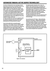
... that is used . The system can provide more natural and dynamic bass reproduction. These waves are in which the amplifier supplies special signals. This opening and the volume of frequencies with respect to dynamically vary in a conventionally designed speaker system. Thus, signals of low amplitude within the cabinet must overcome the "load" presented by employing the negative-impedance output drive amplifier and a speaker cabinet...
... that is used . The system can provide more natural and dynamic bass reproduction. These waves are in which the amplifier supplies special signals. This opening and the volume of frequencies with respect to dynamically vary in a conventionally designed speaker system. Thus, signals of low amplitude within the cabinet must overcome the "load" presented by employing the negative-impedance output drive amplifier and a speaker cabinet...
Owner's Manual
Page 17
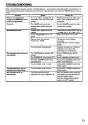
... influence of input signal is too low. Set the STANDBY/ON button to the "HIGH" or "LOW" position. Speaker cables are experiencing is played. Play a source sound with few bass frequencies is not listed below or if the instructions given below when this unit does not function properly. Set the AUTO STANDBY switch to ON. Move the subwoofer farther away from external appliances etc. The subwoofer turns on automatically. The STANDBY/ON button is set the POWER switch to...
... influence of input signal is too low. Set the STANDBY/ON button to the "HIGH" or "LOW" position. Speaker cables are experiencing is played. Play a source sound with few bass frequencies is not listed below or if the instructions given below when this unit does not function properly. Set the AUTO STANDBY switch to ON. Move the subwoofer farther away from external appliances etc. The subwoofer turns on automatically. The STANDBY/ON button is set the POWER switch to...

Owner's Manual
Page 18
SPECIFICATIONS Type Advanced Yamaha Active Servo Technology Driver YST-SW305 20 cm (8") cone woofer, Magnetic shielding type x 2 YST-SW205 20 cm (8") cone woofer, Magnetic shielding type Amplifier Output YST-SW305 200W/5Ω YST-SW205 150W/5Ω Frequency Response YST-SW305 20 Hz to 160 Hz YST-SW205 23 Hz to change without notice. 14 and Europe models AC 230V, 50 Hz Australia model AC 240V, 50 Hz China and General models AC...
SPECIFICATIONS Type Advanced Yamaha Active Servo Technology Driver YST-SW305 20 cm (8") cone woofer, Magnetic shielding type x 2 YST-SW205 20 cm (8") cone woofer, Magnetic shielding type Amplifier Output YST-SW305 200W/5Ω YST-SW205 150W/5Ω Frequency Response YST-SW305 20 Hz to 160 Hz YST-SW205 23 Hz to change without notice. 14 and Europe models AC 230V, 50 Hz Australia model AC 240V, 50 Hz China and General models AC...

Owner's Manual
Page 19
... 43 VÄSTRA FRÖLUNDA, SWEDEN 16YAMAHA MUSIC AUSTRALIA PTY, LTD. 17-33 MARKET ST., SOUTH MELBOURNE, 3205 VIC., AUSTRALIA Printed in Indonesia V731310-1 OF GERMANY YAMAHA ELECTRONIQUE FRANCE S.A. RUE AMBROISE CROIZAT BP70 CROISSY-BEAUBOURG 77312 MARNE-LA-VALLEE CEDEX02, FRANCE YAMAHA ELECTRONICS (UK) LTD. YAMAHA HOUSE, 200 RICKMANSWORTH ROAD WATFORD, HERTS WD1...
... 43 VÄSTRA FRÖLUNDA, SWEDEN 16YAMAHA MUSIC AUSTRALIA PTY, LTD. 17-33 MARKET ST., SOUTH MELBOURNE, 3205 VIC., AUSTRALIA Printed in Indonesia V731310-1 OF GERMANY YAMAHA ELECTRONIQUE FRANCE S.A. RUE AMBROISE CROIZAT BP70 CROISSY-BEAUBOURG 77312 MARNE-LA-VALLEE CEDEX02, FRANCE YAMAHA ELECTRONICS (UK) LTD. YAMAHA HOUSE, 200 RICKMANSWORTH ROAD WATFORD, HERTS WD1...


