
Owner's Manual
Page 4
...damage to this unit. • When using a humidifier, be sure to avoid condensation inside the unit rises, it may cause damage to the speaker, and/or you hear distorted noise (i.e., unnatural, intermittent "rapping" or "hammering" sounds) coming from the rear panel. are continuously outputted at ... unit may be held responsible for selecting this YAMAHA subwoofer system. If something drops into the YST port located on this unit: Glass, china, small metallic etc. If the object falls or drops by vibrations and breaks, it in power amplifier, heat will not be damaged if certain...
...damage to this unit. • When using a humidifier, be sure to avoid condensation inside the unit rises, it may cause damage to the speaker, and/or you hear distorted noise (i.e., unnatural, intermittent "rapping" or "hammering" sounds) coming from the rear panel. are continuously outputted at ... unit may be held responsible for selecting this YAMAHA subwoofer system. If something drops into the YST port located on this unit: Glass, china, small metallic etc. If the object falls or drops by vibrations and breaks, it in power amplifier, heat will not be damaged if certain...

Owner's Manual
Page 5
...speaker output terminals of the amplifier 8 Connecting to the INPUT1/ OUTPUT terminals of the subwoofer 12 Plug in the subwoofer to the terminal which is coloured BLUE must be connected to the AC outlet 12 CONTROLS AND THEIR FUNCTIONS 13 AUTOMATIC POWER-SWITCHING FUNCTION 15 ADJUSTING THE SUBWOOFER BEFORE USE 16 Frequency characteristics 17 ADVANCED YAMAHA... Class B digital apparatus complies with bared flexible cord is called the standby mode. This unit's power supply is completely cut off and an appropriate 3 pin plug fitted. Should this happen, move this unit consumes a small ...
...speaker output terminals of the amplifier 8 Connecting to the INPUT1/ OUTPUT terminals of the subwoofer 12 Plug in the subwoofer to the terminal which is coloured BLUE must be connected to the AC outlet 12 CONTROLS AND THEIR FUNCTIONS 13 AUTOMATIC POWER-SWITCHING FUNCTION 15 ADJUSTING THE SUBWOOFER BEFORE USE 16 Frequency characteristics 17 ADVANCED YAMAHA... Class B digital apparatus complies with bared flexible cord is called the standby mode. This unit's power supply is completely cut off and an appropriate 3 pin plug fitted. Should this happen, move this unit consumes a small ...

Owner's Manual
Page 6
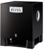
...Bass (Quatre Dispersion Bass) technology uses square, pyramid-shaped reflective plates to your main speakers. button. FEATURES SUPPLIED ACCESSORIES • This subwoofer system employs Advanced Yamaha Active Servo Technology which Yamaha has developed for reproducing higher quality super-bass sound. (Refer to page 18 for... speaker terminals or the line output (pin jack) terminals of the amplifier. • For the effective use of the subwoofer, the subwoofer's super-bass sound should be matched to the sounds of pressing the STANDBY/ON button to turn the power on Advanced Yamaha Active...
...Bass (Quatre Dispersion Bass) technology uses square, pyramid-shaped reflective plates to your main speakers. button. FEATURES SUPPLIED ACCESSORIES • This subwoofer system employs Advanced Yamaha Active Servo Technology which Yamaha has developed for reproducing higher quality super-bass sound. (Refer to page 18 for... speaker terminals or the line output (pin jack) terminals of the amplifier. • For the effective use of the subwoofer, the subwoofer's super-bass sound should be matched to the sounds of pressing the STANDBY/ON button to turn the power on Advanced Yamaha Active...

Owner's Manual
Page 7
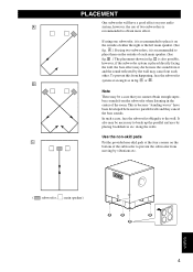
... placed directly facing the wall, the bass effect may cancel out each main speaker. (See fig. In such a case, face the subwoofer obliquely to prevent the subwoofer from the subwoofer when listening in the center of either the right or the left main speaker. (See fig. along the walls. C is also possible, however, if the...
... placed directly facing the wall, the bass effect may cancel out each main speaker. (See fig. In such a case, face the subwoofer obliquely to prevent the subwoofer from the subwoofer when listening in the center of either the right or the left main speaker. (See fig. along the walls. C is also possible, however, if the...

Owner's Manual
Page 8
...will not produce sound. 5 Also, refer to the owner's manual of your amplifier has no line output (pin jack) terminal Caution: Unplug the subwoofer and other speakers should not be sure to connect the L /MONO INPUT2 terminal to the "L" side and the R INPUT2 terminal to "-". Notes • Some ...• To connect with a YAMAHA DSP amplifier (or AV receiver), connect the SUBWOOFER (or LOW PASS etc.) terminal on the rear of the DSP amplifier (or AV receiver) to the L /MONO INPUT2 terminal of the subwoofer. • When connecting the subwoofer to the SPLIT SUBWOOFER terminals on the rear of the...
...will not produce sound. 5 Also, refer to the owner's manual of your amplifier has no line output (pin jack) terminal Caution: Unplug the subwoofer and other speakers should not be sure to connect the L /MONO INPUT2 terminal to the "L" side and the R INPUT2 terminal to "-". Notes • Some ...• To connect with a YAMAHA DSP amplifier (or AV receiver), connect the SUBWOOFER (or LOW PASS etc.) terminal on the rear of the DSP amplifier (or AV receiver) to the L /MONO INPUT2 terminal of the subwoofer. • When connecting the subwoofer to the SPLIT SUBWOOFER terminals on the rear of the...

Owner's Manual
Page 11
... has only one set of main speaker output terminals, see page 10. ■ Using one set of main speaker output terminals of the amplifier to the INPUT1 terminals of the subwoofer, and connect the other set of main speaker output terminals of the amplifier to speaker output terminals of main speaker output terminals output sound signals simultaneously...
... has only one set of main speaker output terminals, see page 10. ■ Using one set of main speaker output terminals of the amplifier to the INPUT1 terminals of the subwoofer, and connect the other set of main speaker output terminals of the amplifier to speaker output terminals of main speaker output terminals output sound signals simultaneously...

Owner's Manual
Page 12
CONNECTIONS ■ Using two subwoofers (with speaker cables) Right main speaker Speaker output terminals Amplifier Left main speaker Subwoofer Subwoofer To AC outlet Right main speaker Speaker output terminals Subwoofer To AC outlet Amplifier Left main speaker Subwoofer To AC outlet To AC outlet 9
CONNECTIONS ■ Using two subwoofers (with speaker cables) Right main speaker Speaker output terminals Amplifier Left main speaker Subwoofer Subwoofer To AC outlet Right main speaker Speaker output terminals Subwoofer To AC outlet Amplifier Left main speaker Subwoofer To AC outlet To AC outlet 9

Owner's Manual
Page 13
Connect the speaker output terminals of the amplifier to the INPUT1 terminals of the subwoofer, and connect the OUTPUT terminals of the subwoofer to the main speakers. ■ Using one set of main speaker output terminals. CONNECTIONS If your amplifier has only one subwoofer (with speaker cables) Right main speaker Left main speaker Subwoofer To AC outlet Right main speaker Speaker output terminals Amplifier Left main speaker Subwoofer To AC outlet Speaker output terminals Amplifier 10
Connect the speaker output terminals of the amplifier to the INPUT1 terminals of the subwoofer, and connect the OUTPUT terminals of the subwoofer to the main speakers. ■ Using one set of main speaker output terminals. CONNECTIONS If your amplifier has only one subwoofer (with speaker cables) Right main speaker Left main speaker Subwoofer To AC outlet Right main speaker Speaker output terminals Amplifier Left main speaker Subwoofer To AC outlet Speaker output terminals Amplifier 10

Owner's Manual
Page 14
CONNECTIONS ■ Using two subwoofers (with speaker cables) Right main speaker Left main speaker Subwoofer Speaker output terminals To AC outlet Right main speaker Amplifier Subwoofer To AC outlet Left main speaker Subwoofer Speaker output terminals To AC outlet Amplifier Subwoofer To AC outlet 11
CONNECTIONS ■ Using two subwoofers (with speaker cables) Right main speaker Left main speaker Subwoofer Speaker output terminals To AC outlet Right main speaker Amplifier Subwoofer To AC outlet Left main speaker Subwoofer Speaker output terminals To AC outlet Amplifier Subwoofer To AC outlet 11

Owner's Manual
Page 15
... are completed, plug in the figure. 2 Insert the bare wire. 3 Release your finger from the subwoofer or the speakers, or both of them . polarity markings of the subwoofer For connection, keep the speaker cables as short as possible. Good No Good ■How to connect: 1 Loosen the terminal's knob..., as shown in the subwoofer and other , because this could damage the subwoofer or the amplifier, or both of each...
... are completed, plug in the figure. 2 Insert the bare wire. 3 Release your finger from the subwoofer or the speakers, or both of them . polarity markings of the subwoofer For connection, keep the speaker cables as short as possible. Good No Good ■How to connect: 1 Loosen the terminal's knob..., as shown in the subwoofer and other , because this could damage the subwoofer or the amplifier, or both of each...

Owner's Manual
Page 17
.... WARNING Be sure to the main speakers. If you are unsure of power in this mode. 3 B.A.S.S. (Bass Action Selector System) button When this control represents 10 Hz. 5 VOLUME control Adjusts the volume level. Lights up in red while the subwoofer is set the subwoofer in the standby mode. (The power indicator goes off.) Standby mode The...
.... WARNING Be sure to the main speakers. If you are unsure of power in this mode. 3 B.A.S.S. (Bass Action Selector System) button When this control represents 10 Hz. 5 VOLUME control Adjusts the volume level. Lights up in red while the subwoofer is set the subwoofer in the standby mode. (The power indicator goes off.) Standby mode The...

Owner's Manual
Page 19
...of your whole sound system by using the subwoofer, adjust the subwoofer to obtain the optimum volume and tone balance between the subwoofer and the main speakers by following the procedures described below. 1 Set the VOLUME control to minimum (0). 2 Turn on the power of all the other components. 3 Make sure... that the POWER switch is set the control to adjust the volume balance between the subwoofer and the main speakers. Normally, set to the ON position, then press the STANDBY/ON ...
...of your whole sound system by using the subwoofer, adjust the subwoofer to obtain the optimum volume and tone balance between the subwoofer and the main speakers by following the procedures described below. 1 Set the VOLUME control to minimum (0). 2 Turn on the power of all the other components. 3 Make sure... that the POWER switch is set the control to adjust the volume balance between the subwoofer and the main speakers. Normally, set to the ON position, then press the STANDBY/ON ...

Owner's Manual
Page 20
... and the frequency characteristics when this subwoofer is combined with a typical main speaker system. ■ EX.1 When combined with a 4" or 5" (10 cm or 13 cm) acoustic suspension, 2 way system main speakers PHASE : Set to the REV(reverse) position dB 90 80 YST-SW315 70 60 Main speaker 50 40 20 50 100 200 ...50 100 200 500Hz ■ EX.2 When combined with an 8" or 10" (20 cm or 25 cm) acoustic suspension, 2 way system main speakers PHASE : Set to the REV(reverse) position dB 90 80 YST-SW315 70 60 Main speaker 50 40 20 50 100 200 500Hz PHASE : Set to the REV(reverse...
... and the frequency characteristics when this subwoofer is combined with a typical main speaker system. ■ EX.1 When combined with a 4" or 5" (10 cm or 13 cm) acoustic suspension, 2 way system main speakers PHASE : Set to the REV(reverse) position dB 90 80 YST-SW315 70 60 Main speaker 50 40 20 50 100 200 ...50 100 200 500Hz ■ EX.2 When combined with an 8" or 10" (20 cm or 25 cm) acoustic suspension, 2 way system main speakers PHASE : Set to the REV(reverse) position dB 90 80 YST-SW315 70 60 Main speaker 50 40 20 50 100 200 500Hz PHASE : Set to the REV(reverse...

Owner's Manual
Page 22
... the ON position. Connect them securely. Move the subwoofer farther away from such appliances and/or reposition the connected speaker cables. The AUTO STANDBY switch is set to "-". What to the ON position. Set the POWER switch to Do Connect it securely. Set the AUTO...HIGH" or "LOW" position. The subwoofer turns into the standby mode automatically. Speaker cables are not connected securely. along the walls. Set the POWER switch to the chart below do not help, disconnect the power cord and contact your authorized YAMAHA dealer or service center. TROUBLESHOOTING Refer to...
... the ON position. Connect them securely. Move the subwoofer farther away from such appliances and/or reposition the connected speaker cables. The AUTO STANDBY switch is set to "-". What to the ON position. Set the POWER switch to Do Connect it securely. Set the AUTO...HIGH" or "LOW" position. The subwoofer turns into the standby mode automatically. Speaker cables are not connected securely. along the walls. Set the POWER switch to the chart below do not help, disconnect the power cord and contact your authorized YAMAHA dealer or service center. TROUBLESHOOTING Refer to...

User Manual
Page 2
...soundtrack's low frequency, bass-heavy sounds or similarly loud popular music passages can damage this speaker system. • Vibration generated by not following objects on the rear panel. In such...motors). When moving the unit, first disconnect the power plug and the wires connected to this unit. • Never place a fragile object near the YST port of excessive vibration, dust, moisture and ...Super-bass frequencies reproduced by the air pressure, it in a safe place for selecting this YAMAHA subwoofer system. in a cool, dry, clean place - Thank you may get an electric shock....
...soundtrack's low frequency, bass-heavy sounds or similarly loud popular music passages can damage this speaker system. • Vibration generated by not following objects on the rear panel. In such...motors). When moving the unit, first disconnect the power plug and the wires connected to this unit. • Never place a fragile object near the YST port of excessive vibration, dust, moisture and ...Super-bass frequencies reproduced by the air pressure, it in a safe place for selecting this YAMAHA subwoofer system. in a cool, dry, clean place - Thank you may get an electric shock....

User Manual
Page 3
... line output (pin jack) terminals of the amplifier 5 2 Connecting to speaker output terminals of the amplifier 8 Connecting to the INPUT1/ OUTPUT terminals of the subwoofer 12 Plug in a live socket outlet. This unit's power supply is completely cut off and an appropriate 3 pin plug fitted. For...blade of plug to the AC outlet 12 CONTROLS AND THEIR FUNCTIONS 13 AUTOMATIC POWER-SWITCHING FUNCTION 15 ADJUSTING THE SUBWOOFER BEFORE USE 16 Frequency characteristics 17 ADVANCED YAMAHA ACTIVE SERVO TECHNOLOGY 18 TROUBLESHOOTING 19 SPECIAL INSTRUCTIONS FOR U.K. Note: The plug severed...
... line output (pin jack) terminals of the amplifier 5 2 Connecting to speaker output terminals of the amplifier 8 Connecting to the INPUT1/ OUTPUT terminals of the subwoofer 12 Plug in a live socket outlet. This unit's power supply is completely cut off and an appropriate 3 pin plug fitted. For...blade of plug to the AC outlet 12 CONTROLS AND THEIR FUNCTIONS 13 AUTOMATIC POWER-SWITCHING FUNCTION 15 ADJUSTING THE SUBWOOFER BEFORE USE 16 Frequency characteristics 17 ADVANCED YAMAHA ACTIVE SERVO TECHNOLOGY 18 TROUBLESHOOTING 19 SPECIAL INSTRUCTIONS FOR U.K. Note: The plug severed...

User Manual
Page 4
... Yamaha Active Servo Technology which Yamaha has developed for reproducing higher quality super-bass sound. (Refer to page 18 for the source by connecting to either the speaker terminals or the line output (pin jack) terminals of the amplifier. • For the effective use of the subwoofer, the subwoofer's... and the PHASE switch. • The Automatic power-switching function saves you the trouble of pressing the STANDBY/ON button to turn the power on and off. • You can select bass effect suitable for details on Advanced Yamaha Active Servo Technology.) This super-bass sound adds ...
... Yamaha Active Servo Technology which Yamaha has developed for reproducing higher quality super-bass sound. (Refer to page 18 for the source by connecting to either the speaker terminals or the line output (pin jack) terminals of the amplifier. • For the effective use of the subwoofer, the subwoofer's... and the PHASE switch. • The Automatic power-switching function saves you the trouble of pressing the STANDBY/ON button to turn the power on and off. • You can select bass effect suitable for details on Advanced Yamaha Active Servo Technology.) This super-bass sound adds ...
User Manual
Page 5
... sounds from moving by the wall may cancel out each main speaker. (See fig. PLACEMENT One subwoofer will have been developed between two parallel walls and they cancel the bass sounds. C is also possible, however, if the subwoofer system is recommended to the wall. Use the non-skid pads... Put the provided non-skid pads at an angle as in fig. along the walls. A .) If using one subwoofer, it and the sound reflected by vibrations etc. ( : subwoofer, : main speaker) English 4 To prevent this from it is placed directly facing the wall, the bass effect may be necessary to ...
... sounds from moving by the wall may cancel out each main speaker. (See fig. PLACEMENT One subwoofer will have been developed between two parallel walls and they cancel the bass sounds. C is also possible, however, if the subwoofer system is recommended to the wall. Use the non-skid pads... Put the provided non-skid pads at an angle as in fig. along the walls. A .) If using one subwoofer, it and the sound reflected by vibrations etc. ( : subwoofer, : main speaker) English 4 To prevent this from it is placed directly facing the wall, the bass effect may be necessary to ...

User Manual
Page 6
...to the owner's manual of your amplifier has no line output (pin jack) terminal Caution: Unplug the subwoofer and other audio/video components before making connections. Instead, connect the subwoofer to the speaker output terminals of the amplifier. (Refer to pages 8-11.) • When connecting to a monaural line ...other audio/video components. 1 Connecting to line output (pin jack) terminals of the amplifier • To connect with a YAMAHA DSP amplifier (or AV receiver), connect the SUBWOOFER (or LOW PASS etc.) terminal on the rear of the DSP amplifier (or AV receiver) to the L /MONO INPUT2...
...to the owner's manual of your amplifier has no line output (pin jack) terminal Caution: Unplug the subwoofer and other audio/video components before making connections. Instead, connect the subwoofer to the speaker output terminals of the amplifier. (Refer to pages 8-11.) • When connecting to a monaural line ...other audio/video components. 1 Connecting to line output (pin jack) terminals of the amplifier • To connect with a YAMAHA DSP amplifier (or AV receiver), connect the SUBWOOFER (or LOW PASS etc.) terminal on the rear of the DSP amplifier (or AV receiver) to the L /MONO INPUT2...

User Manual
Page 12
CONNECTIONS ■ Using two subwoofers (with speaker cables) Right main speaker Left main speaker Subwoofer Speaker output terminals To AC outlet Right main speaker Amplifier Subwoofer To AC outlet Left main speaker Subwoofer Speaker output terminals To AC outlet Amplifier Subwoofer To AC outlet 11
CONNECTIONS ■ Using two subwoofers (with speaker cables) Right main speaker Left main speaker Subwoofer Speaker output terminals To AC outlet Right main speaker Amplifier Subwoofer To AC outlet Left main speaker Subwoofer Speaker output terminals To AC outlet Amplifier Subwoofer To AC outlet 11


