
Owners Manual
Page 1
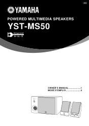
UCA POWERED MULTIMEDIA SPEAKERS YST-MS50 POWERED MULTIMEDIA SPEAKERS YST-MS50 BASS 0 10 OWNER'S MANUAL 1 MODE D'EMPLOI 4 POWERED MULTIMEDIA SPEAKERS VOLUME
UCA POWERED MULTIMEDIA SPEAKERS YST-MS50 POWERED MULTIMEDIA SPEAKERS YST-MS50 BASS 0 10 OWNER'S MANUAL 1 MODE D'EMPLOI 4 POWERED MULTIMEDIA SPEAKERS VOLUME
Owners Manual
Page 2
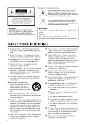
... that produce heat. The power-supply cord or the plug has been damaged; The unit has been exposed to overturn. 7 Wall or Ceiling Mounting - The unit has been dropped, or the enclosure damaged. 16 Servicing - The user should be cleaned only as marked on or pinched by the manufacturer. 13 Nonuse Periods - All other instructions should be followed. 5 Water...
... that produce heat. The power-supply cord or the plug has been damaged; The unit has been exposed to overturn. 7 Wall or Ceiling Mounting - The unit has been dropped, or the enclosure damaged. 16 Servicing - The user should be cleaned only as marked on or pinched by the manufacturer. 13 Nonuse Periods - All other instructions should be followed. 5 Water...
Owners Manual
Page 3
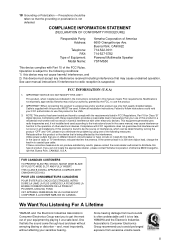
...: Model Name: Yamaha Corporation of radio or TV interference, relocate/reorient the antenna. Buena Park, CA90622 714-522-9011 714-527-5782 Powered Multimedia Speaker YST-MS50 This device complies with this manual, meets FCC requirements. Failure to follow instructions could void your authority, granted by using one of the FCC Rules. This equipment generates/uses radio frequencies and, if not installed and used...
...: Model Name: Yamaha Corporation of radio or TV interference, relocate/reorient the antenna. Buena Park, CA90622 714-522-9011 714-527-5782 Powered Multimedia Speaker YST-MS50 This device complies with this manual, meets FCC requirements. Failure to follow instructions could void your authority, granted by using one of the FCC Rules. This equipment generates/uses radio frequencies and, if not installed and used...
Owners Manual
Page 5
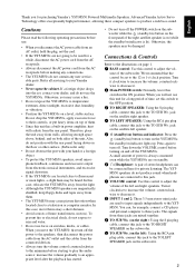
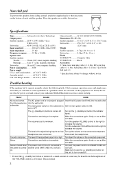
... adjust the volume of stereo headphones can , for purchasing Yamaha's YST-MS50 Powered Multimedia Speakers. You can be set , contact your hand or a foreign object. • To protect the YST-MS50 speakers, avoid microphone feedback, continuous and excessive output from the rear panel. Therefore, place the unit away from these jacks are connected to this jack. 7 VOLUME control: Use this jack to these compact speakers to fluorescent or neon lights, a slight...
... adjust the volume of stereo headphones can , for purchasing Yamaha's YST-MS50 Powered Multimedia Speakers. You can be set , contact your hand or a foreign object. • To protect the YST-MS50 speakers, avoid microphone feedback, continuous and excessive output from the rear panel. Therefore, place the unit away from these jacks are connected to this jack. 7 VOLUME control: Use this jack to these compact speakers to fluorescent or neon lights, a slight...
Owners Manual
Page 6
... Europe models...... The main power switch on ) button (the indicator lights). The level of the signal being input is turned another unit's SWITCHED AC OUTLET. Disconnect the headphones. Make the connections again, firmly, or use a different cable. set to minimum. Turn on the (standby/on the subwoofer is set to OFF. FAULT CAUSE CURE No sound comes The AC power cord is too low. Turn the speaker VOLUME control to the right to operate...
... Europe models...... The main power switch on ) button (the indicator lights). The level of the signal being input is turned another unit's SWITCHED AC OUTLET. Disconnect the headphones. Make the connections again, firmly, or use a different cable. set to minimum. Turn on the (standby/on the subwoofer is set to OFF. FAULT CAUSE CURE No sound comes The AC power cord is too low. Turn the speaker VOLUME control to the right to operate...
Service Manual
Page 1
... as specified. s CONTENTS TO SERVICE PERSONNEL 1 FRONT AND REAR PANELS 1 - 2 SPECIFICATIONS 3 INTERNAL VIEW 4 DISASSEMBLY PROCEDURES 5 PRINTED CIRCUIT BOARD 6 - 8 BLOCK DIAGRAM 9 SCHEMATIC DIAGRAM 10 PARTS LIST 11 - 15 PARTS LIST FOR CARBON RESISTORS 16 YST-MS50(M) 100778 POWERED MULTIMEDIA SPEAKERS YST-MS50(M) SERVICE MANUAL The contents of this Service Manual are continually striving to improve YAMAHA products. WARNING: Failure to follow appropriate service and safety procedures when servicing this product may have therefore...
... as specified. s CONTENTS TO SERVICE PERSONNEL 1 FRONT AND REAR PANELS 1 - 2 SPECIFICATIONS 3 INTERNAL VIEW 4 DISASSEMBLY PROCEDURES 5 PRINTED CIRCUIT BOARD 6 - 8 BLOCK DIAGRAM 9 SCHEMATIC DIAGRAM 10 PARTS LIST 11 - 15 PARTS LIST FOR CARBON RESISTORS 16 YST-MS50(M) 100778 POWERED MULTIMEDIA SPEAKERS YST-MS50(M) SERVICE MANUAL The contents of this Service Manual are continually striving to improve YAMAHA products. WARNING: Failure to follow appropriate service and safety procedures when servicing this product may have therefore...
Service Manual
Page 2
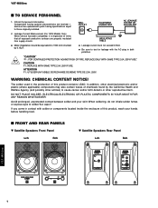
...should be replaced with parts having special characteristics are properly insulated from supply circuits. WARNING: CHEMICAL CONTENT NOTICE! The solder used in contact with the AC plug in ...Speakers Rear Panel Lch Rch YST-MS50(M) 1 q Be sure to cause cancer and/or birth defects or other electrical/electronic and/or plastic (where applicable) components may also contain traces of chemicals found by 0.15µF. WALL OUTLET EQUIPMENT UNDER TEST AC LEAKAGE TESTER OR EQUIVALENT 2. YST-MS50(M) s TO SERVICE PERSONNEL 1. Leakage Current Measurement (For 120V Models...
...should be replaced with parts having special characteristics are properly insulated from supply circuits. WARNING: CHEMICAL CONTENT NOTICE! The solder used in contact with the AC plug in ...Speakers Rear Panel Lch Rch YST-MS50(M) 1 q Be sure to cause cancer and/or birth defects or other electrical/electronic and/or plastic (where applicable) components may also contain traces of chemicals found by 0.15µF. WALL OUTLET EQUIPMENT UNDER TEST AC LEAKAGE TESTER OR EQUIVALENT 2. YST-MS50(M) s TO SERVICE PERSONNEL 1. Leakage Current Measurement (For 120V Models...
Service Manual
Page 3
w Subwoofer Front Panel YST-MS50(M) YST-MS50(M) w Subwoofer Rear Panel U and C models B and G models A model 2
w Subwoofer Front Panel YST-MS50(M) YST-MS50(M) w Subwoofer Rear Panel U and C models B and G models A model 2
Service Manual
Page 4
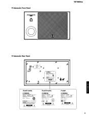
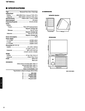
...) x 2 Subwoofer 8 kg (17 lbs. 10 oz) Finish White color Black color Accessories 3.5mm stereo mini plug cable (1.8m) x 1 RCA pin plug cable (1.8m) x 1 8 pin plug cable (1.8m) x 1 8 pcs of nonskid pad x 1set * Specifications subject to change without notice. U USA model C Canadian model A Australian model B British model G European model 159 (6-1/4") q DIMENSIONS q Satellite Speaker 166(6-17/32") 97 (3-13/16") q Subwoofer 178 (7") 321 (12-5/8") 210 (8-1/4") 350 (13-3/4") Unit : mm (inch) YST-MS50(M) 3
...) x 2 Subwoofer 8 kg (17 lbs. 10 oz) Finish White color Black color Accessories 3.5mm stereo mini plug cable (1.8m) x 1 RCA pin plug cable (1.8m) x 1 8 pin plug cable (1.8m) x 1 8 pcs of nonskid pad x 1set * Specifications subject to change without notice. U USA model C Canadian model A Australian model B British model G European model 159 (6-1/4") q DIMENSIONS q Satellite Speaker 166(6-17/32") 97 (3-13/16") q Subwoofer 178 (7") 321 (12-5/8") 210 (8-1/4") 350 (13-3/4") Unit : mm (inch) YST-MS50(M) 3
Service Manual
Page 5
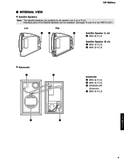
e MAIN (D) P.C.B. y SPEAKER UNIT (Subwoofer) u MAIN (F) P.C.B. w Subwoofer r t Subwoofer r MAIN (E) P.C.B. y u YST-MS50(M) 4 YST-MS50(M) s INTERNAL VIEW w Satellite Speakers Note: The Satellite Speakers are not available. (See page 14 and 15 of the Satellite Speakers are available by the speaker unit (L ch or R ch). t MAIN (A) P.C.B. Individual parts of the PARTS LIST.) Lch Rch qw e Satellite Speaker (L ch) q MAIN (B) P.C.B. Satellite Speaker (R ch) w MAIN (C) P.C.B.
e MAIN (D) P.C.B. y SPEAKER UNIT (Subwoofer) u MAIN (F) P.C.B. w Subwoofer r t Subwoofer r MAIN (E) P.C.B. y u YST-MS50(M) 4 YST-MS50(M) s INTERNAL VIEW w Satellite Speakers Note: The Satellite Speakers are not available. (See page 14 and 15 of the Satellite Speakers are available by the speaker unit (L ch or R ch). t MAIN (A) P.C.B. Individual parts of the PARTS LIST.) Lch Rch qw e Satellite Speaker (L ch) q MAIN (B) P.C.B. Satellite Speaker (R ch) w MAIN (C) P.C.B.
Service Manual
Page 6
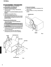
... the front panel ass'y in the direction of the Front Panel Ass'y The front panel assy is fixed to the cabinet with dowels at 6 locations. * As a screwdriver (for slotted head screw) is not damaged so as numbered.) q Disassemble of the Subwoofer 1. Set up the front panel ass'y. c. Front Panel Ass'y 2. YST-MS50(M) s DISASSEMBLY PROCEDURES (Remove parts in the order as to prevent air leakage from...
... the front panel ass'y in the direction of the Front Panel Ass'y The front panel assy is fixed to the cabinet with dowels at 6 locations. * As a screwdriver (for slotted head screw) is not damaged so as numbered.) q Disassemble of the Subwoofer 1. Set up the front panel ass'y. c. Front Panel Ass'y 2. YST-MS50(M) s DISASSEMBLY PROCEDURES (Remove parts in the order as to prevent air leakage from...
Service Manual
Page 7
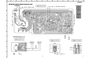
BE 2 RE WH E F TO : SPEAKER (WOOFER) 3 FROM : MAIN ( E ) G H YST-MS50(M) q Semiconductor Location Ref. No. No. IC1 IC2 IC4 IC5 IC6 ... FROM : MAIN ( F ) TO RIGHT SPEAKER TO LEFT SPEAKER WH BE TO : MAIN ( A ) 4 w Satellite Speaker (L ch) MAIN ( B ) P. SPEAKER (MIDRANGE) -+ SPEAKER (TWEETER) +- 2.2µ 5 BL RE RE L TO SUB Wo. 6 6 MAIN ( E ) P. BASS MAIN ( F ) P. POWER TO : MAIN ( A ) 7 B. C. B. A B C D s PRINTED CIRCUIT BOARD (Component side) 1 w Subwoofer BL: U, C BR: A, B, G WH: U, C BE: A, B, G FROM : POWER CORD WH MAIN ( A ) P.
BE 2 RE WH E F TO : SPEAKER (WOOFER) 3 FROM : MAIN ( E ) G H YST-MS50(M) q Semiconductor Location Ref. No. No. IC1 IC2 IC4 IC5 IC6 ... FROM : MAIN ( F ) TO RIGHT SPEAKER TO LEFT SPEAKER WH BE TO : MAIN ( A ) 4 w Satellite Speaker (L ch) MAIN ( B ) P. SPEAKER (MIDRANGE) -+ SPEAKER (TWEETER) +- 2.2µ 5 BL RE RE L TO SUB Wo. 6 6 MAIN ( E ) P. BASS MAIN ( F ) P. POWER TO : MAIN ( A ) 7 B. C. B. A B C D s PRINTED CIRCUIT BOARD (Component side) 1 w Subwoofer BL: U, C BR: A, B, G WH: U, C BE: A, B, G FROM : POWER CORD WH MAIN ( A ) P.
Service Manual
Page 8
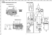
... MIDRENGE SUBWOOFER ~ - IN OUT GND -12 IC5 -B G H C. I. JK5 OL -12 TO RIGHT E SPEAKER 12 G 34 5 OR 67 8 RSP+ IC1 +12 -12 5 7 EQ Amp IC1,2 (NJM4558D) H. B. 3 TO : MAIN ( D ) MAIN ( D ) P. A YST-MS50(M) s PRINTED CIRCUIT BOARD (Component side) 1 2 B w Satellite Speaker (R ch) (POWER) MAIN ( C ) P. Location IC3 Q1 Q2 B2 B2 B2 D 9 E s BLOCK DIAGRAM F Rch SATELLITE SPEAKER JK4 IL IR INPUT 1 JK3 INPUT 2 VOLUME +12...
... MIDRENGE SUBWOOFER ~ - IN OUT GND -12 IC5 -B G H C. I. JK5 OL -12 TO RIGHT E SPEAKER 12 G 34 5 OR 67 8 RSP+ IC1 +12 -12 5 7 EQ Amp IC1,2 (NJM4558D) H. B. 3 TO : MAIN ( D ) MAIN ( D ) P. A YST-MS50(M) s PRINTED CIRCUIT BOARD (Component side) 1 2 B w Satellite Speaker (R ch) (POWER) MAIN ( C ) P. Location IC3 Q1 Q2 B2 B2 B2 D 9 E s BLOCK DIAGRAM F Rch SATELLITE SPEAKER JK4 IL IR INPUT 1 JK3 INPUT 2 VOLUME +12...
Service Manual
Page 9
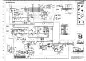
... marked Z and must be replaced with parts having specifications equal to those originally installed. * Schematic diagram is subject to change without notice. 10 MAIN ( B ) K YST-MS50(M) PIN CONNECTION DIAGRAM OF TRANSISTORS, DIODES AND ICS. 1SS133 NJM4556AL Anode Cathode RBV-402 8 1 NJM4558D - + 2SA1015 (O, Y) 2SC1815 (Y, GR) 2SC2878 (A, B) 4 8 1 STK408-040E E CB 20 2SK304 (E) 1 D GS NJM78M12FA NJM79M12FA 1: OUTPUT 2: COMMON 3: INPUT 321 1:COMMON 2:INPUT 3:OUTPUT 321 IC1, 2, 7 : NJM4558D Dual...
... marked Z and must be replaced with parts having specifications equal to those originally installed. * Schematic diagram is subject to change without notice. 10 MAIN ( B ) K YST-MS50(M) PIN CONNECTION DIAGRAM OF TRANSISTORS, DIODES AND ICS. 1SS133 NJM4556AL Anode Cathode RBV-402 8 1 NJM4558D - + 2SA1015 (O, Y) 2SC1815 (Y, GR) 2SC2878 (A, B) 4 8 1 STK408-040E E CB 20 2SK304 (E) 1 D GS NJM78M12FA NJM79M12FA 1: OUTPUT 2: COMMON 3: INPUT 321 1:COMMON 2:INPUT 3:OUTPUT 321 IC1, 2, 7 : NJM4558D Dual...
Service Manual
Page 10
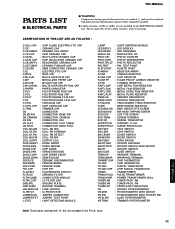
... VR.TRIM : TRIMMER POTENTIOMETER Note) Those parts marked with parts having special characteristics are marked Z and must be replaced with "#" are not included in the P.C.B. q Carbon resistors (1/6W or 1/4W) are not included in the ELECTRICAL PARTS List. ass'y. 11 YST-MS50(M) YST-MS50(M) PARTS LIST s ELECTRICAL PARTS s WARNING Components having specifications equal to last page. ELECTROLYTIC CAP C.CE...
... VR.TRIM : TRIMMER POTENTIOMETER Note) Those parts marked with parts having special characteristics are marked Z and must be replaced with "#" are not included in the P.C.B. q Carbon resistors (1/6W or 1/4W) are not included in the ELECTRICAL PARTS List. ass'y. 11 YST-MS50(M) YST-MS50(M) PARTS LIST s ELECTRICAL PARTS s WARNING Components having specifications equal to last page. ELECTROLYTIC CAP C.CE...

Service Manual
Page 15
... kΩ 1.0 MΩ 1.2 MΩ 1.5 MΩ 1.8 MΩ 2.2 MΩ 3.3 MΩ 3.9 MΩ 4.7 MΩ 1/4W Type Part No. 1/6W Type Part No. YST-MS50(M) Parts List for Carbon Resistors Value 1.0 Ω 1.8 Ω 2.2 Ω 3.3 Ω 4.7 Ω 5.6 Ω 10 Ω 15 Ω...; 3.0 kΩ 3.3 kΩ 3.6 kΩ 3.9 kΩ 4.7 kΩ 5.1 kΩ 5.6 kΩ 6.8 kΩ 8.2 kΩ 9.1 kΩ 1/4W Type Part No. 1/6W Type Part No. HF45 7100 HF45 7100 HF45 7110 HF45 7110 HJ35 7120 HF85 7120 HF45 7130 HF45 7130 HF45 7150 HF45 7150 HF45 7180 HF45...
... kΩ 1.0 MΩ 1.2 MΩ 1.5 MΩ 1.8 MΩ 2.2 MΩ 3.3 MΩ 3.9 MΩ 4.7 MΩ 1/4W Type Part No. 1/6W Type Part No. YST-MS50(M) Parts List for Carbon Resistors Value 1.0 Ω 1.8 Ω 2.2 Ω 3.3 Ω 4.7 Ω 5.6 Ω 10 Ω 15 Ω...; 3.0 kΩ 3.3 kΩ 3.6 kΩ 3.9 kΩ 4.7 kΩ 5.1 kΩ 5.6 kΩ 6.8 kΩ 8.2 kΩ 9.1 kΩ 1/4W Type Part No. 1/6W Type Part No. HF45 7100 HF45 7100 HF45 7110 HF45 7110 HJ35 7120 HF85 7120 HF45 7130 HF45 7130 HF45 7150 HF45 7150 HF45 7180 HF45...


