
Owners Manual
Page 3
...in a residential environment will not occur in the USA. 3. Buena Park, CA90622 714-522-9011 714-527-5782 Powered Multimedia Speaker YST-MS50 This device complies with FCC regulations does not guarantee that the grounding or polarization is suspected. IMPORTANT NOTICE: DO NOT MODIFY THIS UNIT...to be determined by turning the product "OFF" and "ON", please try to eliminate the problem by Yamaha may cause interference harmful to coaxial type cable. Compliance with Part 15 of America 6600 Orangethorpe Ave. FCC INFORMATION (U.S.A) 1. If this product is being affected by the ...
...in a residential environment will not occur in the USA. 3. Buena Park, CA90622 714-522-9011 714-527-5782 Powered Multimedia Speaker YST-MS50 This device complies with FCC regulations does not guarantee that the grounding or polarization is suspected. IMPORTANT NOTICE: DO NOT MODIFY THIS UNIT...to be determined by turning the product "OFF" and "ON", please try to eliminate the problem by Yamaha may cause interference harmful to coaxial type cable. Compliance with Part 15 of America 6600 Orangethorpe Ave. FCC INFORMATION (U.S.A) 1. If this product is being affected by the ...
Owners Manual
Page 5
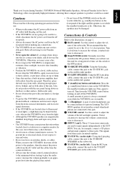
... • Always turn the volume control counterclockwise to the minimum before making any connections. • The YST-MS50s do not contain any user serviceable parts. In this case, move the YST-MS50, first turn off the power to the speakers, then disconnect the power cable from the AC ...not turn off the POWER switch on the subwoofer while the (standby/on) button on the front panel of stereo headphones can , for purchasing Yamaha's YST-MS50 Powered Multimedia Speakers. Turn down on the subwoofer. 2 You can be connected here for a while, disconnect the AC power cord from the ...
... • Always turn the volume control counterclockwise to the minimum before making any connections. • The YST-MS50s do not contain any user serviceable parts. In this case, move the YST-MS50, first turn off the power to the speakers, then disconnect the power cable from the AC ...not turn off the POWER switch on the subwoofer while the (standby/on) button on the front panel of stereo headphones can , for purchasing Yamaha's YST-MS50 Powered Multimedia Speakers. Turn down on the subwoofer. 2 You can be connected here for a while, disconnect the AC power cord from the ...
Service Manual
Page 1
...5 PRINTED CIRCUIT BOARD 6 - 8 BLOCK DIAGRAM 9 SCHEMATIC DIAGRAM 10 PARTS LIST 11 - 15 PARTS LIST FOR CARBON RESISTORS 16 YST-MS50(M) 100778 For these reasons, we advise all work before you apply power... to this buss). Modifications are, therefore, inevitable and specifications are already known and understood by grounding yourself to the ground buss in personal injury, destruction of expensive components, and failure of authorized YAMAHA...
...5 PRINTED CIRCUIT BOARD 6 - 8 BLOCK DIAGRAM 9 SCHEMATIC DIAGRAM 10 PARTS LIST 11 - 15 PARTS LIST FOR CARBON RESISTORS 16 YST-MS50(M) 100778 For these reasons, we advise all work before you apply power... to this buss). Modifications are, therefore, inevitable and specifications are already known and understood by grounding yourself to the ground buss in personal injury, destruction of expensive components, and failure of authorized YAMAHA...
Service Manual
Page 2
...found by 0.15µF. s FRONT AND REAR PANELS w Satellite Speakers Front Panel Lch Rch w Satellite Speakers Rear Panel Lch Rch YST-MS50(M) 1 WALL OUTLET EQUIPMENT UNDER TEST AC LEAKAGE TESTER OR EQUIVALENT 2. In addition, other reproductive harm. q Meter impedance should be ...plastic (where applicable) components may also contain traces of this product contains LEAD. q Be sure to test for leakage with parts having special characteristics are properly insulated from supply circuits. WARNING: CHEMICAL CONTENT NOTICE! Avoid prolonged, unprotected contact between solder and ...
...found by 0.15µF. s FRONT AND REAR PANELS w Satellite Speakers Front Panel Lch Rch w Satellite Speakers Rear Panel Lch Rch YST-MS50(M) 1 WALL OUTLET EQUIPMENT UNDER TEST AC LEAKAGE TESTER OR EQUIVALENT 2. In addition, other reproductive harm. q Meter impedance should be ...plastic (where applicable) components may also contain traces of this product contains LEAD. q Be sure to test for leakage with parts having special characteristics are properly insulated from supply circuits. WARNING: CHEMICAL CONTENT NOTICE! Avoid prolonged, unprotected contact between solder and ...
Service Manual
Page 5
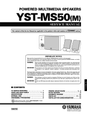
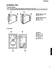
Satellite Speaker (R ch) w MAIN (C) P.C.B. t MAIN (A) P.C.B. e MAIN (D) P.C.B. y SPEAKER UNIT (Subwoofer) u MAIN (F) P.C.B. YST-MS50(M) s INTERNAL VIEW w Satellite Speakers Note: The Satellite Speakers are not available. (See page 14 and 15 of the PARTS LIST.) Lch Rch qw e Satellite Speaker (L ch) q MAIN (B) P.C.B. w Subwoofer r t Subwoofer r MAIN (E) P.C.B. y u YST-MS50(M) 4 Individual parts of the Satellite Speakers are available by the speaker unit (L ch or R ch).
Satellite Speaker (R ch) w MAIN (C) P.C.B. t MAIN (A) P.C.B. e MAIN (D) P.C.B. y SPEAKER UNIT (Subwoofer) u MAIN (F) P.C.B. YST-MS50(M) s INTERNAL VIEW w Satellite Speakers Note: The Satellite Speakers are not available. (See page 14 and 15 of the PARTS LIST.) Lch Rch qw e Satellite Speaker (L ch) q MAIN (B) P.C.B. w Subwoofer r t Subwoofer r MAIN (E) P.C.B. y u YST-MS50(M) 4 Individual parts of the Satellite Speakers are available by the speaker unit (L ch or R ch).
Service Manual
Page 6
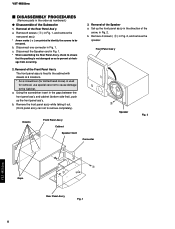
a. Removal of the Rear Panel Ass'y. Front Panel Ass'y 2. a. c. Remove 4 screws ( w ) in Fig. 1. YST-MS50(M) s DISASSEMBLY PROCEDURES (Remove parts in the order as to prevent air leakage from occurring. 3. Remove 8 screws ( q ) in Fig. 1, and remove the rear panel ass'y. * Arrow marks ( ) are printed to ...
a. Removal of the Rear Panel Ass'y. Front Panel Ass'y 2. a. c. Remove 4 screws ( w ) in Fig. 1. YST-MS50(M) s DISASSEMBLY PROCEDURES (Remove parts in the order as to prevent air leakage from occurring. 3. Remove 8 screws ( q ) in Fig. 1, and remove the rear panel ass'y. * Arrow marks ( ) are printed to ...
Service Manual
Page 9
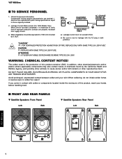
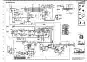
...DC electric volt meter. * Components having special characteristics are marked Z and must be replaced with parts having specifications equal to those originally installed. * Schematic diagram is subject to change without notice. 10...27.1 0 0 -25.5 25.6 -0.1 -0.1 -0.2 -0.2 -27.1 0 -0.1 -0.1 -24.3 F G H I .C 0 -1.5 0 00 0 0 0 J TO SUB Wo. TO SUB Wo. MAIN ( B ) K YST-MS50(M) PIN CONNECTION DIAGRAM OF TRANSISTORS, DIODES AND ICS. 1SS133 NJM4556AL Anode Cathode RBV-402 8 1 NJM4558D - + 2SA1015 (O, Y) 2SC1815 (Y, GR) 2SC2878 (A, B) 4 8 1 STK408-040E E CB 20 2SK304 (E) 1 D GS...
...DC electric volt meter. * Components having special characteristics are marked Z and must be replaced with parts having specifications equal to those originally installed. * Schematic diagram is subject to change without notice. 10...27.1 0 0 -25.5 25.6 -0.1 -0.1 -0.2 -0.2 -27.1 0 -0.1 -0.1 -24.3 F G H I .C 0 -1.5 0 00 0 0 0 J TO SUB Wo. TO SUB Wo. MAIN ( B ) K YST-MS50(M) PIN CONNECTION DIAGRAM OF TRANSISTORS, DIODES AND ICS. 1SS133 NJM4556AL Anode Cathode RBV-402 8 1 NJM4558D - + 2SA1015 (O, Y) 2SC1815 (Y, GR) 2SC2878 (A, B) 4 8 1 STK408-040E E CB 20 2SK304 (E) 1 D GS...
Service Manual
Page 10
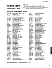
... SCR.CUP : CUP TITE SCREW SCR.TERM : SCREW TERMINAL SCR.TR : SCREW, TRANSISTOR SUPRT.PCB : SUPPORT, P.C.B. For the parts No. ABBREVIATIONS IN THIS LIST ARE AS FOLLOWS : C.A.EL.CHP : CHIP ALUMI. YST-MS50(M) PARTS LIST s ELECTRICAL PARTS s WARNING Components having special characteristics are not included in the P.C.B. q Carbon resistors (1/6W or 1/4W) are marked Z and...
... SCR.CUP : CUP TITE SCREW SCR.TERM : SCREW TERMINAL SCR.TR : SCREW, TRANSISTOR SUPRT.PCB : SUPPORT, P.C.B. For the parts No. ABBREVIATIONS IN THIS LIST ARE AS FOLLOWS : C.A.EL.CHP : CHIP ALUMI. YST-MS50(M) PARTS LIST s ELECTRICAL PARTS s WARNING Components having special characteristics are not included in the P.C.B. q Carbon resistors (1/6W or 1/4W) are marked Z and...

Service Manual
Page 15
YST-MS50(M) Parts List for Carbon Resistors Value 1.0 Ω 1.8 Ω 2.2 Ω 3.3 Ω 4.7 Ω 5.6 Ω 10 Ω 15 Ω 22 &#...; 1.8 kΩ 2.0 kΩ 2.2 kΩ 2.4 kΩ 2.7 kΩ 3.0 kΩ 3.3 kΩ 3.6 kΩ 3.9 kΩ 4.7 kΩ 5.1 kΩ 5.6 kΩ 6.8 kΩ 8.2 kΩ 9.1 kΩ 1/4W Type Part No. 1/6W Type Part No. HJ35 3100 HF85 3100 HJ35 3180 ❊ HJ35 3220 HF85 3220 HJ35 3330 HF85 3330 HJ35 3470 HF85 3470 HJ35 3560 HF85 3560...1/4W Type HJ35 10mm 1/4W Type HF45 1/6W Type HF85 5mm 1992 16 YST-MS50(M)
YST-MS50(M) Parts List for Carbon Resistors Value 1.0 Ω 1.8 Ω 2.2 Ω 3.3 Ω 4.7 Ω 5.6 Ω 10 Ω 15 Ω 22 &#...; 1.8 kΩ 2.0 kΩ 2.2 kΩ 2.4 kΩ 2.7 kΩ 3.0 kΩ 3.3 kΩ 3.6 kΩ 3.9 kΩ 4.7 kΩ 5.1 kΩ 5.6 kΩ 6.8 kΩ 8.2 kΩ 9.1 kΩ 1/4W Type Part No. 1/6W Type Part No. HJ35 3100 HF85 3100 HJ35 3180 ❊ HJ35 3220 HF85 3220 HJ35 3330 HF85 3330 HJ35 3470 HF85 3470 HJ35 3560 HF85 3560...1/4W Type HJ35 10mm 1/4W Type HF45 1/6W Type HF85 5mm 1992 16 YST-MS50(M)


