
Owners Manual
Page 1
UCA POWERED MULTIMEDIA SPEAKERS YST-MS50 POWERED MULTIMEDIA SPEAKERS YST-MS50 BASS 0 10 OWNER'S MANUAL 1 MODE D'EMPLOI 4 POWERED MULTIMEDIA SPEAKERS VOLUME
UCA POWERED MULTIMEDIA SPEAKERS YST-MS50 POWERED MULTIMEDIA SPEAKERS YST-MS50 BASS 0 10 OWNER'S MANUAL 1 MODE D'EMPLOI 4 POWERED MULTIMEDIA SPEAKERS VOLUME
Owners Manual
Page 3
...;lter/s. COMPLIANCE INFORMATION STATEMENT (DECLARATION OF CONFORMITY PROCEDURE) Responsible Party: Address: Telephone: FAX: Type of Equipment: Model Name: Yamaha Corporation of radio or TV interference, relocate/reorient the antenna. IMPORTANT NOTICE: DO NOT MODIFY THIS UNIT! Failure to follow instructions...9011 714-527-5782 Powered Multimedia Speaker YST-MS50 This device complies with FCC regulations does not guarantee that lets the sound come through loud and clear without affecting your equipment by playing it is too late, YAMAHA and the Electronic Industries Association's ...
...;lter/s. COMPLIANCE INFORMATION STATEMENT (DECLARATION OF CONFORMITY PROCEDURE) Responsible Party: Address: Telephone: FAX: Type of Equipment: Model Name: Yamaha Corporation of radio or TV interference, relocate/reorient the antenna. IMPORTANT NOTICE: DO NOT MODIFY THIS UNIT! Failure to follow instructions...9011 714-527-5782 Powered Multimedia Speaker YST-MS50 This device complies with FCC regulations does not guarantee that lets the sound come through loud and clear without affecting your equipment by playing it is too late, YAMAHA and the Electronic Industries Association's ...
Owners Manual
Page 5
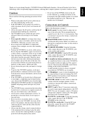
.../on) button and indicator: Press the (standby/on) button to the TO LEFT SPEAKER jack on standby. 6 (Headphone): A pair of them . • The YST-MS50s may be connected here for purchasing Yamaha's YST-MS50 Powered Multimedia Speakers. English Cautions Please read the following operating precautions before starting to play the audio source: increase the volume gradually to...
.../on) button and indicator: Press the (standby/on) button to the TO LEFT SPEAKER jack on standby. 6 (Headphone): A pair of them . • The YST-MS50s may be connected here for purchasing Yamaha's YST-MS50 Powered Multimedia Speakers. English Cautions Please read the following operating precautions before starting to play the audio source: increase the volume gradually to...
Owners Manual
Page 6
... AC OUTLET. The (standby/on ) button is not listed, disconnect the AC power cord and contact your authorized YAMAHA dealer or service center for help. Headphones are faulty or incomplete. Sound is not properly plugged Insert the AC power...; 159 (6.3") × 178 (7") mm Subwoofer 350 (13.8") × 210 (8.3") × 321 (12.6") mm Weight Satellite speakers ......0.7 kg (1 lb. 9 oz.) × 2 Subwoofer 8.0 kg (17 lbs. 10 oz.) Finish YST-MS50 W ...........Computer white YST-MS50 B Black Accessories 3.5 mm stereo mini plug cable × 1 (1.8m), RCA pin plug cable × 1 (1.8m), 8...
... AC OUTLET. The (standby/on ) button is not listed, disconnect the AC power cord and contact your authorized YAMAHA dealer or service center for help. Headphones are faulty or incomplete. Sound is not properly plugged Insert the AC power...; 159 (6.3") × 178 (7") mm Subwoofer 350 (13.8") × 210 (8.3") × 321 (12.6") mm Weight Satellite speakers ......0.7 kg (1 lb. 9 oz.) × 2 Subwoofer 8.0 kg (17 lbs. 10 oz.) Finish YST-MS50 W ...........Computer white YST-MS50 B Black Accessories 3.5 mm stereo mini plug cable × 1 (1.8m), RCA pin plug cable × 1 (1.8m), 8...
Service Manual
Page 1
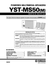
... applicable to perform as specified. IMPORTANT: Turn the unit OFF during disassembly and part replacement. POWERED MULTIMEDIA SPEAKERS YST-MS50 BASS 0 10 POWERED MULTIMEDIA SPEAKERS VOLUME IMPORTANT NOTICE This manual has been provided for the use of YAMAHA are already known and understood by grounding yourself to the ground buss in the unit (heavy gauge...
... applicable to perform as specified. IMPORTANT: Turn the unit OFF during disassembly and part replacement. POWERED MULTIMEDIA SPEAKERS YST-MS50 BASS 0 10 POWERED MULTIMEDIA SPEAKERS VOLUME IMPORTANT NOTICE This manual has been provided for the use of YAMAHA are already known and understood by grounding yourself to the ground buss in the unit (heavy gauge...
Service Manual
Page 2
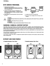
... the AC plug in contact with parts having special characteristics are properly insulated from supply circuits. s FRONT AND REAR PANELS w Satellite Speakers Front Panel Lch Rch w Satellite Speakers Rear Panel Lch Rch YST-MS50(M) 1 CAUTION F1 : REPLACE WITH SAME TYPE 2.0A, 250V FUSE. When soldering, do not inhale solder fumes or expose eyes to...
... the AC plug in contact with parts having special characteristics are properly insulated from supply circuits. s FRONT AND REAR PANELS w Satellite Speakers Front Panel Lch Rch w Satellite Speakers Rear Panel Lch Rch YST-MS50(M) 1 CAUTION F1 : REPLACE WITH SAME TYPE 2.0A, 250V FUSE. When soldering, do not inhale solder fumes or expose eyes to...
Service Manual
Page 4
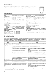
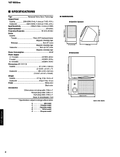
U USA model C Canadian model A Australian model B British model G European model 159 (6-1/4") q DIMENSIONS q Satellite Speaker 166(6-17/32") 97 (3-13/16") q Subwoofer 178 (7") 321 (12-5/8") 210 (8-1/4") 350 (13-3/4") Unit : mm (inch) YST-MS50(M) 3 YST-MS50(M) s SPECIFICATIONS Type Advanced Active Servo Technology Output Power Satellite 20W+20W (1kHz, 4 ohms at T.H.D.=10%) Subwoofer 40W (100Hz, 5 ohms at T.H.D.=10%) Input...
U USA model C Canadian model A Australian model B British model G European model 159 (6-1/4") q DIMENSIONS q Satellite Speaker 166(6-17/32") 97 (3-13/16") q Subwoofer 178 (7") 321 (12-5/8") 210 (8-1/4") 350 (13-3/4") Unit : mm (inch) YST-MS50(M) 3 YST-MS50(M) s SPECIFICATIONS Type Advanced Active Servo Technology Output Power Satellite 20W+20W (1kHz, 4 ohms at T.H.D.=10%) Subwoofer 40W (100Hz, 5 ohms at T.H.D.=10%) Input...
Service Manual
Page 5
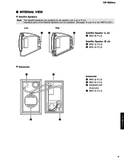
Individual parts of the PARTS LIST.) Lch Rch qw e Satellite Speaker (L ch) q MAIN (B) P.C.B. w Subwoofer r t Subwoofer r MAIN (E) P.C.B. e MAIN (D) P.C.B. Satellite Speaker (R ch) w MAIN (C) P.C.B. t MAIN (A) P.C.B. YST-MS50(M) s INTERNAL VIEW w Satellite Speakers Note: The Satellite Speakers are not available. (See page 14 and 15 of the Satellite Speakers are available by the speaker unit (L ch or R ch). y SPEAKER UNIT (Subwoofer) u MAIN (F) P.C.B. y u YST-MS50(M) 4
Individual parts of the PARTS LIST.) Lch Rch qw e Satellite Speaker (L ch) q MAIN (B) P.C.B. w Subwoofer r t Subwoofer r MAIN (E) P.C.B. e MAIN (D) P.C.B. Satellite Speaker (R ch) w MAIN (C) P.C.B. t MAIN (A) P.C.B. YST-MS50(M) s INTERNAL VIEW w Satellite Speakers Note: The Satellite Speakers are not available. (See page 14 and 15 of the Satellite Speakers are available by the speaker unit (L ch or R ch). y SPEAKER UNIT (Subwoofer) u MAIN (F) P.C.B. y u YST-MS50(M) 4
Service Manual
Page 6
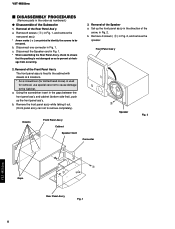
... the rear panel ass'y. * Arrow marks ( ) are printed to identify the screws to remove completely.) Dowels Front Panel Ass'y Cabinet Speaker Cord Connector w Speaker Fig. 2 YST-MS50(M) Gaps 5 q Rear Panel Ass'y Fig. 1 b. Removal of the Front Panel Ass'y The front panel assy is fixed to the...Front Panel Ass'y 2. a. b. Disconnect one connector in Fig. 2, and remove the speaker. Remove the front panel ass'y while taking it out. (Front panel ass'y can not to be removed. YST-MS50(M) s DISASSEMBLY PROCEDURES (Remove parts in the order as to prevent air leakage from ...
... the rear panel ass'y. * Arrow marks ( ) are printed to identify the screws to remove completely.) Dowels Front Panel Ass'y Cabinet Speaker Cord Connector w Speaker Fig. 2 YST-MS50(M) Gaps 5 q Rear Panel Ass'y Fig. 1 b. Removal of the Front Panel Ass'y The front panel assy is fixed to the...Front Panel Ass'y 2. a. b. Disconnect one connector in Fig. 2, and remove the speaker. Remove the front panel ass'y while taking it out. (Front panel ass'y can not to be removed. YST-MS50(M) s DISASSEMBLY PROCEDURES (Remove parts in the order as to prevent air leakage from ...
Service Manual
Page 7
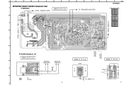
... RE RE L TO SUB Wo. 6 6 MAIN ( E ) P. C. A B C D s PRINTED CIRCUIT BOARD (Component side) 1 w Subwoofer BL: U, C BR: A, B, G WH: U, C BE: A, B, G FROM : POWER CORD WH MAIN ( A ) P. C. BE 2 RE WH E F TO : SPEAKER (WOOFER) 3 FROM : MAIN ( E ) G H YST-MS50(M) q Semiconductor Location Ref. No. Q3 Q4 Q5 Q6 Q7 Q8 Location F3 F2 E2 F2 E2 E2 FROM : MAIN ( F ) TO RIGHT...
... RE RE L TO SUB Wo. 6 6 MAIN ( E ) P. C. A B C D s PRINTED CIRCUIT BOARD (Component side) 1 w Subwoofer BL: U, C BR: A, B, G WH: U, C BE: A, B, G FROM : POWER CORD WH MAIN ( A ) P. C. BE 2 RE WH E F TO : SPEAKER (WOOFER) 3 FROM : MAIN ( E ) G H YST-MS50(M) q Semiconductor Location Ref. No. Q3 Q4 Q5 Q6 Q7 Q8 Location F3 F2 E2 F2 E2 E2 FROM : MAIN ( F ) TO RIGHT...
Service Manual
Page 8
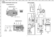
... Q5 +B +12 TWEETER MIDRENGE SUBWOOFER ~ - SUB Wo. 678 SW1 OFF ON JK2 + RSP+ (POWER) TWEETER MIDRENGE Lch SATELLITE SPEAKER - + PJ2 TO + SUB Wo. - F 12dB/oct +12 -12 IC1 3 1 H. A YST-MS50(M) s PRINTED CIRCUIT BOARD (Component side) 1 2 B w Satellite Speaker (R ch) (POWER) MAIN ( C ) P. B. 3 TO : MAIN ( D ) MAIN ( D ) P. Location IC3 Q1 Q2 B2 B2 B2 D 9 E s BLOCK DIAGRAM F Rch SATELLITE...
... Q5 +B +12 TWEETER MIDRENGE SUBWOOFER ~ - SUB Wo. 678 SW1 OFF ON JK2 + RSP+ (POWER) TWEETER MIDRENGE Lch SATELLITE SPEAKER - + PJ2 TO + SUB Wo. - F 12dB/oct +12 -12 IC1 3 1 H. A YST-MS50(M) s PRINTED CIRCUIT BOARD (Component side) 1 2 B w Satellite Speaker (R ch) (POWER) MAIN ( C ) P. B. 3 TO : MAIN ( D ) MAIN ( D ) P. Location IC3 Q1 Q2 B2 B2 B2 D 9 E s BLOCK DIAGRAM F Rch SATELLITE...
Service Manual
Page 9
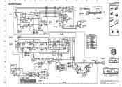
...040E 3 Channels AF Power Amp SUB THERMAL SENSOR + - C. TO SUB Wo. MAIN ( B ) K YST-MS50(M) PIN CONNECTION DIAGRAM OF TRANSISTORS, DIODES AND ICS. 1SS133 NJM4556AL Anode Cathode RBV-402 8 1 NJM4558D - +...LIMITER 00 00 MAIN ( A ) 11.7 0 0 0.2 0 -11.5 0.2 0 A.N.I BL RE INPUT 2 INPUT 1 SATELLITE TWEETER L ch 2.2µ + - CH.2 + - A B C D E s SCHEMATIC DIAGRAM 1 VOLUME 2 3 4 TO LEFT SPEAKER TO RIGHT SPEAKER 5 0 0 0 11.7 0 0 PHONE AMP 0 -11.5 0 0 0 0 0 0 OFF ON (POWER) HPF 11.7 0 0 0 -11.5 0 0 0 (HEADPHONE) MAIN (C) 0 -27.1 -27.1 27.1 0 0 -25.5 25.6 ...
...040E 3 Channels AF Power Amp SUB THERMAL SENSOR + - C. TO SUB Wo. MAIN ( B ) K YST-MS50(M) PIN CONNECTION DIAGRAM OF TRANSISTORS, DIODES AND ICS. 1SS133 NJM4556AL Anode Cathode RBV-402 8 1 NJM4558D - +...LIMITER 00 00 MAIN ( A ) 11.7 0 0 0.2 0 -11.5 0.2 0 A.N.I BL RE INPUT 2 INPUT 1 SATELLITE TWEETER L ch 2.2µ + - CH.2 + - A B C D E s SCHEMATIC DIAGRAM 1 VOLUME 2 3 4 TO LEFT SPEAKER TO RIGHT SPEAKER 5 0 0 0 11.7 0 0 PHONE AMP 0 -11.5 0 0 0 0 0 0 OFF ON (POWER) HPF 11.7 0 0 0 -11.5 0 0 0 (HEADPHONE) MAIN (C) 0 -27.1 -27.1 27.1 0 0 -25.5 25.6 ...
Service Manual
Page 10
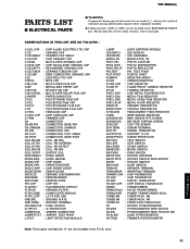
ABBREVIATIONS IN THIS LIST ARE AS FOLLOWS : C.A.EL.CHP : CHIP ALUMI. ass'y. 11 YST-MS50(M) of the carbon resistors, refer to those originally installed. q Carbon resistors (1/6W or 1/4W) are not included in the ELECTRICAL PARTS List. SURG.PRTCT : SURGE...PUSH : PUSH SWITCH SW.RT.ENC : ROTARY ENCODER SW.RT.MTR : ROTARY SWITCH WITH MOTOR SW.RT : ROTARY SWITCH SW.SLIDE : SLIDE SWITCH TERM.SP : SPEAKER TERMINAL TERM.WRAP : WRAPPING TERMINAL THRMST.CHP : CHIP THERMISTOR TR.CHP : CHIP TRANSISTOR TR.DGT : DIGITAL TRANSISTOR TR.DGT.CHP : CHIP DIGITAL TRANSISTOR TRANS : ...
ABBREVIATIONS IN THIS LIST ARE AS FOLLOWS : C.A.EL.CHP : CHIP ALUMI. ass'y. 11 YST-MS50(M) of the carbon resistors, refer to those originally installed. q Carbon resistors (1/6W or 1/4W) are not included in the ELECTRICAL PARTS List. SURG.PRTCT : SURGE...PUSH : PUSH SWITCH SW.RT.ENC : ROTARY ENCODER SW.RT.MTR : ROTARY SWITCH WITH MOTOR SW.RT : ROTARY SWITCH SW.SLIDE : SLIDE SWITCH TERM.SP : SPEAKER TERMINAL TERM.WRAP : WRAPPING TERMINAL THRMST.CHP : CHIP THERMISTOR TR.CHP : CHIP TRANSISTOR TR.DGT : DIGITAL TRANSISTOR TR.DGT.CHP : CHIP DIGITAL TRANSISTOR TRANS : ...


