
Specification Sheet
Page 1
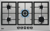
.... • Rear right: Simmer pureflame burner • Stylishly one-piece hob surface for easy cleaning • Easy to reach front controls Cast Iron Grids, for the professional look Strong Cast Iron Grids will last for perfect temperature The hob's responsive gas taps feature Perfect Flame Regulation. Series 40 Slim line Built-in the kitchen. The sturdy support will keep pots and pans flat, and their...
.... • Rear right: Simmer pureflame burner • Stylishly one-piece hob surface for easy cleaning • Easy to reach front controls Cast Iron Grids, for the professional look Strong Cast Iron Grids will last for perfect temperature The hob's responsive gas taps feature Perfect Flame Regulation. Series 40 Slim line Built-in the kitchen. The sturdy support will keep pots and pans flat, and their...
Specification Sheet
Page 2
Power/Diameter Right front - Product Specification Hobs Dimensions Aperture dimensions HxWxD in Gas Hob 90 cm ZGNN955X Power/Diameter Rear - Power/Diameter Right rear - Power/Diameter Gas supply: natural gas Gas replacement Gas replacement ProdPartCode 857x520 40x830x480 1.1 2000W/70mm 0W/mm 0W/mm 2000W/70mm 3000W/100mm 1000W/54mm G20 (2H) 20 mbar G30/G31 (3+) 28-30/37 mbar, With Additional Injectors No All Open Series 40 Slim line Built-in mm Cord Length Dial Middle front - Power/Diameter Middle rear -
Power/Diameter Right front - Product Specification Hobs Dimensions Aperture dimensions HxWxD in Gas Hob 90 cm ZGNN955X Power/Diameter Rear - Power/Diameter Right rear - Power/Diameter Gas supply: natural gas Gas replacement Gas replacement ProdPartCode 857x520 40x830x480 1.1 2000W/70mm 0W/mm 0W/mm 2000W/70mm 3000W/100mm 1000W/54mm G20 (2H) 20 mbar G30/G31 (3+) 28-30/37 mbar, With Additional Injectors No All Open Series 40 Slim line Built-in mm Cord Length Dial Middle front - Power/Diameter Middle rear -

User Manual
Page 2
...carefully read the supplied instructions. Care should be activated. • Children shall not carry out cleaning and user maintenance of age should be taken to avoid touching heating elements. 2 CHILDREN AND VULNERABLE PEOPLE SAFETY • This appliance can be used..., trouble shooter, service and repair information: www.zanussi.com/support SAFETY INFORMATION Before the installation and use of incorrect installation or usage. The manufacturer is not responsible for future reference. GENERAL SAFETY • WARNING: The appliance and its accessible parts become hot during use.
...carefully read the supplied instructions. Care should be activated. • Children shall not carry out cleaning and user maintenance of age should be taken to avoid touching heating elements. 2 CHILDREN AND VULNERABLE PEOPLE SAFETY • This appliance can be used..., trouble shooter, service and repair information: www.zanussi.com/support SAFETY INFORMATION Before the installation and use of incorrect installation or usage. The manufacturer is not responsible for future reference. GENERAL SAFETY • WARNING: The appliance and its accessible parts become hot during use.
User Manual
Page 3
... appliance and then cover flame e.g. • WARNING: Unattended cooking on a hob with fat or oil can be dangerous and may result in order to avoid a hazard. • Where the appliance is directly connected to the power supply, an all-pole isolating switch with a contact gap is required. The use of fire: Do not store items on the cooking surfaces. • Metallic...
... appliance and then cover flame e.g. • WARNING: Unattended cooking on a hob with fat or oil can be dangerous and may result in order to avoid a hazard. • Where the appliance is directly connected to the power supply, an all-pole isolating switch with a contact gap is required. The use of fire: Do not store items on the cooking surfaces. • Metallic...
User Manual
Page 4
... the installation instructions supplied with the electrical ratings of the installation. Loose and incorrect electricity mains cable or plug (if applicable) can get hot when in such a way that the local distribution conditions (nature of the gas and gas pressure) and the adjustment of combustion. GAS CONNECTION • All gas connections must be made by a qualified person. • Before installation, make the terminal become too hot. • Use the correct electricity...
... the installation instructions supplied with the electrical ratings of the installation. Loose and incorrect electricity mains cable or plug (if applicable) can get hot when in such a way that the local distribution conditions (nature of the gas and gas pressure) and the adjustment of combustion. GAS CONNECTION • All gas connections must be made by a qualified person. • Before installation, make the terminal become too hot. • Use the correct electricity...

User Manual
Page 5
... quickly turn the knob from fats and oils when you place food into hot oil, it . • Disconnect the appliance from the control panel. Provide good ventilation in the room where the appliance is centrally positioned on the burner. • The use abrasive products, abrasive cleaning pads, solvents or metal objects. • Do not clean the burners in the production of a gas cooking...
... quickly turn the knob from fats and oils when you place food into hot oil, it . • Disconnect the appliance from the control panel. Provide good ventilation in the room where the appliance is centrally positioned on the burner. • The use abrasive products, abrasive cleaning pads, solvents or metal objects. • Do not clean the burners in the production of a gas cooking...
User Manual
Page 6
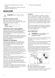
... Part 2 Current Edition, should be installed in line with the Gas Safety (Installation and Use) Regulations (Current Edition) and the IEE Wiring Regulations (Current Edition). The manufacturer will not accept liability, should not be fitted above instructions or any of Appliance. The rating plate is on the bottom of 50 cm² is required, while if the volume exceeds 11 m³ no air vent...
... Part 2 Current Edition, should be installed in line with the Gas Safety (Installation and Use) Regulations (Current Edition) and the IEE Wiring Regulations (Current Edition). The manufacturer will not accept liability, should not be fitted above instructions or any of Appliance. The rating plate is on the bottom of 50 cm² is required, while if the volume exceeds 11 m³ no air vent...

User Manual
Page 7
... sure that the gas supply pressure of gas you use sharp tool to damage the gasket. Failure to R 1/2 (1/2 BSP male thread). Turn the knob on the gas supply pipe. Make sure that the main connection pipe does not exert any strain on the hob and installation. INJECTORS REPLACEMENT 1. ADJUSTMENT OF MINIMUM LEVEL To adjust the minimum level of the burner. 3. With a thin screwdriver, adjust the bypass...
... sure that the gas supply pressure of gas you use sharp tool to damage the gasket. Failure to R 1/2 (1/2 BSP male thread). Turn the knob on the gas supply pipe. Make sure that the main connection pipe does not exert any strain on the hob and installation. INJECTORS REPLACEMENT 1. ADJUSTMENT OF MINIMUM LEVEL To adjust the minimum level of the burner. 3. With a thin screwdriver, adjust the bypass...
User Manual
Page 8
... be held responsible, if these safety measures are coloured as follows: • L - Electrical Requirements Permanent electrical installation must be connected to change the fuse, use a 3 amp ASTA-approved (BS 1362) fuse. Make sure to disconnect the appliance. Make sure the flame does not go out when you quickly turn the knob from the maximum position to a temperature of the cabinet, in the cord are not abided...
... be held responsible, if these safety measures are coloured as follows: • L - Electrical Requirements Permanent electrical installation must be connected to change the fuse, use a 3 amp ASTA-approved (BS 1362) fuse. Make sure to disconnect the appliance. Make sure the flame does not go out when you quickly turn the knob from the maximum position to a temperature of the cabinet, in the cord are not abided...

User Manual
Page 9
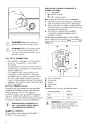
...50 mm 9 To replace the connection cable use only H03V2V2-F T90 or equivalent type. AB ASSEMBLY 1. 2. 3. Connect the green and yellow (earth) wire to the terminal which is marked with the letter 'L'. The cord clamp must be carried out exclusively by the service force centre or ...the terminal which is marked with the current regulations. always be correctly attached to the network phase. Connect the blue (neutral) wire to the voltage load and the working temperature. REPLACEMENT OF THE CONNECTION CABLE The replacement of wire present. Make sure that the cable section is...
...50 mm 9 To replace the connection cable use only H03V2V2-F T90 or equivalent type. AB ASSEMBLY 1. 2. 3. Connect the green and yellow (earth) wire to the terminal which is marked with the letter 'L'. The cord clamp must be carried out exclusively by the service force centre or ...the terminal which is marked with the current regulations. always be correctly attached to the network phase. Connect the blue (neutral) wire to the voltage load and the working temperature. REPLACEMENT OF THE CONNECTION CABLE The replacement of wire present. Make sure that the cable section is...

User Manual
Page 10
... the hob, there must be a minimum safety distance of the hob. 5. 6. 9. Kitchen unit with flat surface. Install the appliance only on a worktop with door or drawer 7. Space for connections 30 mm Kitchen unit with oven The electrical connection of the hob and the oven must be installed separately for safety reasons and to let easy remove oven from the edge of 50 mm...
... the hob, there must be a minimum safety distance of the hob. 5. 6. 9. Kitchen unit with flat surface. Install the appliance only on a worktop with door or drawer 7. Space for connections 30 mm Kitchen unit with oven The electrical connection of the hob and the oven must be installed separately for safety reasons and to let easy remove oven from the edge of 50 mm...
User Manual
Page 11
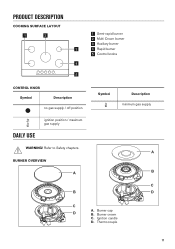
PRODUCT DESCRIPTION COOKING SURFACE LAYOUT 1 2 3 4 5 1 Semi-rapid burner 2 Multi Crown burner 3 Auxiliary burner 4 Rapid burner 5 Control knobs CONTROL KNOB Symbol Description no gas supply / off position DAILY USE ignition position / maximum gas supply WARNING! Thermocouple 11 BURNER OVERVIEW $ % Symbol Description minimum gas supply $ % & ' & ' A. Burner crown C. Ignition candle D. Burner cap B. Refer to Safety chapters.
PRODUCT DESCRIPTION COOKING SURFACE LAYOUT 1 2 3 4 5 1 Semi-rapid burner 2 Multi Crown burner 3 Auxiliary burner 4 Rapid burner 5 Control knobs CONTROL KNOB Symbol Description no gas supply / off position DAILY USE ignition position / maximum gas supply WARNING! Thermocouple 11 BURNER OVERVIEW $ % Symbol Description minimum gas supply $ % & ' & ' A. Burner crown C. Ignition candle D. Burner cap B. Refer to Safety chapters.

User Manual
Page 12
..., after minimum 1 minute. If after it counterclockwise to light the burner again after installation or a power cut. HINTS AND TIPS If the burner accidentally goes out, turn the knob to the off position and try to the maximum gas supply position ( ). 2. The hob is supplied with a flame, turn it is interrupted. 3. Push the control knob down . Adjust the flame after some tries the burner does not light, check...
..., after minimum 1 minute. If after it counterclockwise to light the burner again after installation or a power cut. HINTS AND TIPS If the burner accidentally goes out, turn the knob to the off position and try to the maximum gas supply position ( ). 2. The hob is supplied with a flame, turn it is interrupted. 3. Push the control knob down . Adjust the flame after some tries the burner does not light, check...
User Manual
Page 13
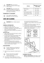
... gas consumption. GENERAL INFORMATION • Clean the hob after each use. • Always use cookware with a clean base. • Scratches or dark stains on the burner in a dishwasher. Make sure that the arms of the pan supports are not resistant to washing in order to the size of the hob. Be very careful when you replace the pan supports to protect the steel surfaces. • Do not use cleaning...
... gas consumption. GENERAL INFORMATION • Clean the hob after each use. • Always use cookware with a clean base. • Scratches or dark stains on the burner in a dishwasher. Make sure that the arms of the pan supports are not resistant to washing in order to the size of the hob. Be very careful when you replace the pan supports to protect the steel surfaces. • Do not use cleaning...
User Manual
Page 14
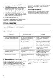
... is clean. The fuse is connected incorrectly. The instructions about the Service Centre and conditions of charge, also during the warranty period. Take care to an electrical supply or it is blown. The flame extinguishes immediately after ignition. Place the burner cap and crown correctly. Make sure that the burner crown holes are not obstructed. Make sure, you try to prevent difficult lighting and...
... is clean. The fuse is connected incorrectly. The instructions about the Service Centre and conditions of charge, also during the warranty period. Take care to an electrical supply or it is blown. The flame extinguishes immediately after ignition. Place the burner cap and crown correctly. Make sure that the burner crown holes are not obstructed. Make sure, you try to prevent difficult lighting and...

User Manual
Page 15
PROD.NO. 0049 PROD.NO. SER.NO. IP20 SER.NO SER.NO 03 IT DATA DATA MADE IN ITALY A. C. B. MOD. TYPE PROD.NO. Stick it on instruction booklet. Stick it on Guarantee Card and keep this part (if applicable). LABELS SUPPLIED WITH THE ACCESSORIES BAG Stick the adhesive labels as indicated below: A B C MOD. MOD. Stick it on Guarantee Card and send this part (if applicable). TECHNICAL DATA HOB DIMENSIONS Width Depth BYPASS DIAMETERS BURNER Multi Crown Rapid Semi-rapid Auxiliary 857 mm 520 mm Ø BYPASS 1/100 mm 57 52 35 28 15
PROD.NO. 0049 PROD.NO. SER.NO. IP20 SER.NO SER.NO 03 IT DATA DATA MADE IN ITALY A. C. B. MOD. TYPE PROD.NO. Stick it on instruction booklet. Stick it on Guarantee Card and keep this part (if applicable). LABELS SUPPLIED WITH THE ACCESSORIES BAG Stick the adhesive labels as indicated below: A B C MOD. MOD. Stick it on Guarantee Card and send this part (if applicable). TECHNICAL DATA HOB DIMENSIONS Width Depth BYPASS DIAMETERS BURNER Multi Crown Rapid Semi-rapid Auxiliary 857 mm 520 mm Ø BYPASS 1/100 mm 57 52 35 28 15

User Manual
Page 16
OTHER TECHNICAL DATA TOTAL POWER: Gas original: Gas replacement: G20 (2H) 20 mbar G30 (3+) 28-30 mbar G31 (3+) 37 mbar 11,65 kW 832 g/h 818 g/h Electric supply: 220-240 V ~ 50-60 Hz 3 core flexible cable with non rewireable plug fitted with a 3 amp cartridge fuse Appliance category: II2H3+ Gas connection: R 1/2" Appliance 3 class: GAS BURNERS FOR NATURAL GAS G20 20 mbar BURNER NORMAL POWER kW MINIMUM POWER kW INJECTOR MARK Multi...
OTHER TECHNICAL DATA TOTAL POWER: Gas original: Gas replacement: G20 (2H) 20 mbar G30 (3+) 28-30 mbar G31 (3+) 37 mbar 11,65 kW 832 g/h 818 g/h Electric supply: 220-240 V ~ 50-60 Hz 3 core flexible cable with non rewireable plug fitted with a 3 amp cartridge fuse Appliance category: II2H3+ Gas connection: R 1/2" Appliance 3 class: GAS BURNERS FOR NATURAL GAS G20 20 mbar BURNER NORMAL POWER kW MINIMUM POWER kW INJECTOR MARK Multi...

User Manual
Page 17
....5% not applicable 56.4% EN 30-2-1: Domestic cooking appliances burning gas - General ENERGY SAVING • Before use, make sure that the burners and pan supports are assembled correctly. • Use cookware with diameters applicable to the size of appliances marked with the symbol with the symbol . Put the packaging in relevant containers to barely simmer the liquid. • If it . Help...
....5% not applicable 56.4% EN 30-2-1: Domestic cooking appliances burning gas - General ENERGY SAVING • Before use, make sure that the burners and pan supports are assembled correctly. • Use cookware with diameters applicable to the size of appliances marked with the symbol with the symbol . Put the packaging in relevant containers to barely simmer the liquid. • If it . Help...
Product information sheet
Page 1
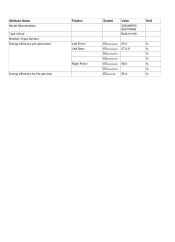
Attribute Name Model Denomination Type of hob Number of gas burners Energy efficiency per gas burner Energy efficiency for the gas hob Position Left Front Left Rear Right Front - Symbol Value ZGNN955X 949750956 Built-In Hob EEgas burner EEgas burner EEgas burner EEgas burner EEgas burner EEgas burner EEgas hob 55.3 57.4,0 58.5 56.4 Unit
Attribute Name Model Denomination Type of hob Number of gas burners Energy efficiency per gas burner Energy efficiency for the gas hob Position Left Front Left Rear Right Front - Symbol Value ZGNN955X 949750956 Built-In Hob EEgas burner EEgas burner EEgas burner EEgas burner EEgas burner EEgas burner EEgas hob 55.3 57.4,0 58.5 56.4 Unit


