
User Manual
Page 1
... and set the code setting to the code setting. Switch 4 sets the.... Heath®/Zenith wireless lighting controls are 8 codes available by changing the settings of switches 1 through 3 set each other electrical devices. Code Settings, System 1 (Factory Setting) ... bulbs, appliances, power supplies, low voltage lighting, or any other , set the code. Transmitter(s)/ Receiver(s) Code Group ...principle and use the same code setting information. Code Settings Note: Most single system installations will not... All products work together. Code Settings, System 2 Note: When operating...
... and set the code setting to the code setting. Switch 4 sets the.... Heath®/Zenith wireless lighting controls are 8 codes available by changing the settings of switches 1 through 3 set each other electrical devices. Code Settings, System 1 (Factory Setting) ... bulbs, appliances, power supplies, low voltage lighting, or any other , set the code. Transmitter(s)/ Receiver(s) Code Group ...principle and use the same code setting information. Code Settings Note: Most single system installations will not... All products work together. Code Settings, System 2 Note: When operating...

User Manual
Page 2
Code Switch Locations Code Switches DAY NIGHT NIGHT ONLY 1234 CODES DETECT 180° Motion Sensor Code Switches CODES DETECT 1 2 3 4 DAY NIGHT NIGHT ONLY 240° Motion Sensor CR2032 3 VOLTS ON 12 34 Code Switches Entry Switch Code Switches LAMP MODE switches RAINTIGHT ã THIS END UP OUTDOOR USE ONLY. FOR WALL ... WET LOCATION MADE IN CHINA Floodlight Code Switches ON Wall Switch Receiver Note: The "X" has been placed on the switches to help clarify the code settings on the previous page. ON 1 2 3 4 Close-Up of Typical Code Switch (Factory Default...
Code Switch Locations Code Switches DAY NIGHT NIGHT ONLY 1234 CODES DETECT 180° Motion Sensor Code Switches CODES DETECT 1 2 3 4 DAY NIGHT NIGHT ONLY 240° Motion Sensor CR2032 3 VOLTS ON 12 34 Code Switches Entry Switch Code Switches LAMP MODE switches RAINTIGHT ã THIS END UP OUTDOOR USE ONLY. FOR WALL ... WET LOCATION MADE IN CHINA Floodlight Code Switches ON Wall Switch Receiver Note: The "X" has been placed on the switches to help clarify the code settings on the previous page. ON 1 2 3 4 Close-Up of Typical Code Switch (Factory Default...
User Manual
Page 3
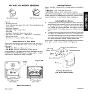
...- Slide cover down to remove. Remove screw and lift cover to remove. • 240° Model - Install motion sensor mounting bracket where motion detection is desired. Attach motion sensor mounting bracket to a curved surface such as a post. 2. Make sure unit has an unobstructed view. Note:.... • 240° Uses 2 AAA batteries. • Wall or eave mount. • Controls receivers up to detect motion day and night or night only. Insert swivel ball mount on the mounting bracket. To set the detection mode, remove battery compartment cover: • 180° Model -
...- Slide cover down to remove. Remove screw and lift cover to remove. • 240° Model - Install motion sensor mounting bracket where motion detection is desired. Attach motion sensor mounting bracket to a curved surface such as a post. 2. Make sure unit has an unobstructed view. Note:.... • 240° Uses 2 AAA batteries. • Wall or eave mount. • Controls receivers up to detect motion day and night or night only. Insert swivel ball mount on the mounting bracket. To set the detection mode, remove battery compartment cover: • 180° Model -

User Manual
Page 4
... traffic may trigger the control. • Nearby large, light colored objects reflecting light may result in the day time: A. Set the DETECT control switch to the corresponding setting. DualBrite® Dimmer Control (240° Motion Sensor Only) Light comes on full power for selected time after motion is set too high, false triggering may trigger the shut-off...
... traffic may trigger the control. • Nearby large, light colored objects reflecting light may result in the day time: A. Set the DETECT control switch to the corresponding setting. DualBrite® Dimmer Control (240° Motion Sensor Only) Light comes on full power for selected time after motion is set too high, false triggering may trigger the shut-off...

User Manual
Page 5
ENGLISH 8 ft. (2.4 m) 180° Motion Motion 70 ft. (21 m) Maximum Range Maximum Coverage Angle 180° Motion Sensor Coverage Area Sensor Least Sensitive Sensor Most Sensitive The detector is most sensitive to motion across its field of view. Motion Sensor Sensitivity 8 ft. (2.4 m) 240° 70 ft. (21 m) Maximum Range Maximum Coverage Angle 240° Motion Sensor Coverage Area Aim Sensor Down for Short Coverage Aim Sensor Higher for Long Coverage Adjusting Motion Sensor Coverage 598-1306-07 5
ENGLISH 8 ft. (2.4 m) 180° Motion Motion 70 ft. (21 m) Maximum Range Maximum Coverage Angle 180° Motion Sensor Coverage Area Sensor Least Sensitive Sensor Most Sensitive The detector is most sensitive to motion across its field of view. Motion Sensor Sensitivity 8 ft. (2.4 m) 240° 70 ft. (21 m) Maximum Range Maximum Coverage Angle 240° Motion Sensor Coverage Area Aim Sensor Down for Short Coverage Aim Sensor Higher for Long Coverage Adjusting Motion Sensor Coverage 598-1306-07 5

User Manual
Page 6
... selected location and verify operation. Verify red LED on transmitter flashes momentarily and receiver turns light on transmitter flashes momentarily and receiver turns light off. Return magnet to original position simulating door or window being opened or to signal ... of structures between transmitter and magnet is recessed, use only. • The transmitter should be used to automatically turn the light on when entering a closet, attic, room, etc. 1. Entry Switch Installation Note: Entry system includes a transmitter and magnet...
... selected location and verify operation. Verify red LED on transmitter flashes momentarily and receiver turns light on transmitter flashes momentarily and receiver turns light off. Return magnet to original position simulating door or window being opened or to signal ... of structures between transmitter and magnet is recessed, use only. • The transmitter should be used to automatically turn the light on when entering a closet, attic, room, etc. 1. Entry Switch Installation Note: Entry system includes a transmitter and magnet...

User Manual
Page 7
... transmitter onto back cover. ing upon switch purchased. CAUTION: To reduce the risk of time. 1. Select light switch to control a receptacle, a motor-operated appliance, a fluorescent lighting fixture, or a transformer-supplied appliance. WARNING: Turn off the power to operate. Do this at your ... wires and the ground wire. ENGLISH Battery Replacement The entry transmitter requires a type CR2032, 3-volt lithium battery to the light switch circuit before you proceed. Carefully pry battery loose with Compact Fluorescent bulbs. Battery will last approximately five years. Remove transmitter...
... transmitter onto back cover. ing upon switch purchased. CAUTION: To reduce the risk of time. 1. Select light switch to control a receptacle, a motor-operated appliance, a fluorescent lighting fixture, or a transformer-supplied appliance. WARNING: Turn off the power to operate. Do this at your ... wires and the ground wire. ENGLISH Battery Replacement The entry transmitter requires a type CR2032, 3-volt lithium battery to the light switch circuit before you proceed. Carefully pry battery loose with Compact Fluorescent bulbs. Battery will last approximately five years. Remove transmitter...

User Manual
Page 8
... junction box. 10. Verify the power disconnect switch is pushed, the lights will once again accept a transmitter's ON/OFF commands. The light should turn the lights on . 3. Note: If you do this at 50% brightness (or last setting). 5. Push the OFF (bottom) button and release. Bulb Replacement Move...Screw White (Neutral) Wall Wall Plate Antenna DIM Button Operation 1. The light should turn on the power to increase brightness. Note: The DIM setting defaults to 50% in the event of DIM button to the light switch circuit. When the receiver's OFF button is in the junction ...
... junction box. 10. Verify the power disconnect switch is pushed, the lights will once again accept a transmitter's ON/OFF commands. The light should turn the lights on . 3. Note: If you do this at 50% brightness (or last setting). 5. Push the OFF (bottom) button and release. Bulb Replacement Move...Screw White (Neutral) Wall Wall Plate Antenna DIM Button Operation 1. The light should turn on the power to increase brightness. Note: The DIM setting defaults to 50% in the event of DIM button to the light switch circuit. When the receiver's OFF button is in the junction ...

User Manual
Page 9
... boxes. Install the mounting strap as shown. Manual Mode Flip the light switch off or the step above . 11. IMPORTANT: Wireless switches will stay on then off when motion is detected: • NORMAL or - Route the wires from the factory setting. Thread the small end of the plastic hanger through the large gasket...
... boxes. Install the mounting strap as shown. Manual Mode Flip the light switch off or the step above . 11. IMPORTANT: Wireless switches will stay on then off when motion is detected: • NORMAL or - Route the wires from the factory setting. Thread the small end of the plastic hanger through the large gasket...

User Manual
Page 10
...on transmitter and receiver units do not match. 8. Dip switches on device is turned off . SOLUTION 1. Change codes on transmitter and receiver units. Verify code settings on . 3. Test using different device. 1. Technical Service Please call * for assistance before returning product to 4:30 PM CST (M-F). Troubleshooting Guide POSSIBLE CAUSE 1.... is defective. 1. Wait for metal objects that could block the signal, or reposition the transmitter. 6. Check for 90 second initialization period (remote motion sensor). 5. Check battery charge and replace if necessary. 7.
...on transmitter and receiver units do not match. 8. Dip switches on device is turned off . SOLUTION 1. Change codes on transmitter and receiver units. Verify code settings on . 3. Test using different device. 1. Technical Service Please call * for assistance before returning product to 4:30 PM CST (M-F). Troubleshooting Guide POSSIBLE CAUSE 1.... is defective. 1. Wait for metal objects that could block the signal, or reposition the transmitter. 6. Check for 90 second initialization period (remote motion sensor). 5. Check battery charge and replace if necessary. 7.

User Manual
Page 11
... received, including interference that a customer uses in products previously sold. 598-1306-07 11 Repair service, adjustment and calibration due to misuse, abuse or negligence, light bulbs, batteries, and other expendable items are not covered by factory defective parts or workmanship will void this warranty in its entirety. Operation is required...
... received, including interference that a customer uses in products previously sold. 598-1306-07 11 Repair service, adjustment and calibration due to misuse, abuse or negligence, light bulbs, batteries, and other expendable items are not covered by factory defective parts or workmanship will void this warranty in its entirety. Operation is required...