
Service Guide
Page 60
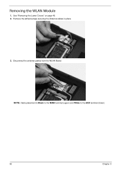
Disconnect the antenna cables from the WLAN Board. NOTE: Cable placement is Black to the MAIN terminal (upper) and White to the AUX terminal (lower). 50 Chapter 3 See "Removing the Lower Covers" on page 46. 2. Removing the WLAN Module 1. Remove the adhesive tape securing the Antenna cables in place. 3.
Disconnect the antenna cables from the WLAN Board. NOTE: Cable placement is Black to the MAIN terminal (upper) and White to the AUX terminal (lower). 50 Chapter 3 See "Removing the Lower Covers" on page 46. 2. Removing the WLAN Module 1. Remove the adhesive tape securing the Antenna cables in place. 3.

Service Guide
Page 69
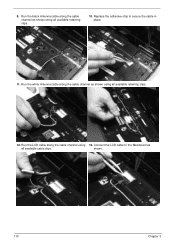
Remove the black Antenna cable from the chassis. 11. Chapter 3 59 Remove the adhesive tape securing the Antenna cable to expose the Hinge Covers. 10. Open the LCD Panel to the full extent to the Upper Cover. 8. Repeat the process for the right side Hinge Cover. Ensure that the cable is completely free of the retaining clips all the way to remove the cover from the cable channel as shown, and lift to the hinge well. 9. Press the left side Hinge Cover inward, as shown. 7.
Remove the black Antenna cable from the chassis. 11. Chapter 3 59 Remove the adhesive tape securing the Antenna cable to expose the Hinge Covers. 10. Open the LCD Panel to the full extent to the Upper Cover. 8. Repeat the process for the right side Hinge Cover. Ensure that the cable is completely free of the retaining clips all the way to remove the cover from the cable channel as shown, and lift to the hinge well. 9. Press the left side Hinge Cover inward, as shown. 7.
Service Guide
Page 120
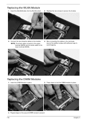
Replace the adhesive strip to the Mainboard as shown using 13. shown. 110 Chapter 3 Run the black Antenna cable along the cable channel as shown using all available cable clips. Run the LCD cable along the cable channel as all available retaining clips. 10. Connect the LCD cable to secure the cable in place. 11. 9. Run the white Antenna cable along the cable channel using all available retaining clips. 12.
Replace the adhesive strip to the Mainboard as shown using 13. shown. 110 Chapter 3 Run the black Antenna cable along the cable channel as shown using all available cable clips. Run the LCD cable along the cable channel as all available retaining clips. 10. Connect the LCD cable to secure the cable in place. 11. 9. Run the white Antenna cable along the cable channel using all available retaining clips. 12.
Service Guide
Page 126
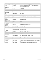
NOTE: The black cable connects to the upper terminal (MAIN) and the white cable to lock the DIMM module in place. 3. Insert the WLAN Module into the WLAN ...
NOTE: The black cable connects to the upper terminal (MAIN) and the white cable to lock the DIMM module in place. 3. Insert the WLAN Module into the WLAN ...
Service Guide
Page 186
Vendor PLDS VGA Chip None NB Chipset AMD SB Chipset ATI Keyboard eMACHINES LAN Atheros WiFi Antenna WNC Audio Codec Realtek A cover Quanta Wistron B cover Camera Suyin Chicony Card Reader Software Wireless LAN Foxconn Foxconn Type NSM8XS Description ...-Multi DRIVE 12.7mm Tray DL 8X DS8A3S LF W/O bezel SATA UMA UMA (AMD) AMDRS780MN AMDRS780MN AMDSB710 AMDSB710 EM-7T Keyboard eMACHINES EM-7T HM50/70 Internal 17 Standard Black AR8132L Atheros AR8132L PIFA PIFA ALC272X Realtek Audio Codec ALC272X Normal wi IMR Normal wi IMR Mirror w/Camera Mirror w/Camera 0.3M DV...
Vendor PLDS VGA Chip None NB Chipset AMD SB Chipset ATI Keyboard eMACHINES LAN Atheros WiFi Antenna WNC Audio Codec Realtek A cover Quanta Wistron B cover Camera Suyin Chicony Card Reader Software Wireless LAN Foxconn Foxconn Type NSM8XS Description ...-Multi DRIVE 12.7mm Tray DL 8X DS8A3S LF W/O bezel SATA UMA UMA (AMD) AMDRS780MN AMDRS780MN AMDSB710 AMDSB710 EM-7T Keyboard eMACHINES EM-7T HM50/70 Internal 17 Standard Black AR8132L Atheros AR8132L PIFA PIFA ALC272X Realtek Audio Codec ALC272X Normal wi IMR Normal wi IMR Mirror w/Camera Mirror w/Camera 0.3M DV...

