

Service Guide
Page 7
...16 Hardware Specifications and Configurations 17 System Utilities 25 BIOS Setup Utility 25 Navigating the BIOS Utility 25 eMachines E627 BIOS 26 Information 26 Main 27 Security 28 Boot 31 Exit 32 BIOS Flash Utilities 33 DOS Flash Utility 34 WinFlash Utility 35 Remove HDD/BIOS Password Utilities 36 Machine Disassembly and Replacement 41 Disassembly Requirements 41 Pre-disassembly Instructions 42 Disassembly Process 42 External Module Disassembly Process 43 External Modules Disassembly Flowchart 43 Removing the Battery Pack 44 Removing the SD Dummy Card 45 Removing the...
...16 Hardware Specifications and Configurations 17 System Utilities 25 BIOS Setup Utility 25 Navigating the BIOS Utility 25 eMachines E627 BIOS 26 Information 26 Main 27 Security 28 Boot 31 Exit 32 BIOS Flash Utilities 33 DOS Flash Utility 34 WinFlash Utility 35 Remove HDD/BIOS Password Utilities 36 Machine Disassembly and Replacement 41 Disassembly Requirements 41 Pre-disassembly Instructions 42 Disassembly Process 42 External Module Disassembly Process 43 External Modules Disassembly Flowchart 43 Removing the Battery Pack 44 Removing the SD Dummy Card 45 Removing the...

Service Guide
Page 8
... Replacing the Hard Disk Drive Module 114 Replacing the WLAN Module 116 Replacing the DIMM Modules 116 Replacing the ODD Module 117 Replacing the Lower Covers 117 Replacing the SD Dummy Card 118 Replacing the Battery 119 Troubleshooting 121 Common Problems 121 Power On Issue 122 No Display Issue 123 Random Loss of BIOS Settings 124 LCD Failure 125 Built-In Keyboard Failure 125 TouchPad Failure 126 Internal Speaker Failure 126 HDD Not Operating Correctly 128 ODD Failure 129 Wireless Function...
... Replacing the Hard Disk Drive Module 114 Replacing the WLAN Module 116 Replacing the DIMM Modules 116 Replacing the ODD Module 117 Replacing the Lower Covers 117 Replacing the SD Dummy Card 118 Replacing the Battery 119 Troubleshooting 121 Common Problems 121 Power On Issue 122 No Display Issue 123 Random Loss of BIOS Settings 124 LCD Failure 125 Built-In Keyboard Failure 125 TouchPad Failure 126 Internal Speaker Failure 126 HDD Not Operating Correctly 128 ODD Failure 129 Wireless Function...

Service Guide
Page 15
.... Turns the computer on and off . Indicates the status of wireless LAN communication. Enables/disables the wireless LAN function. Touch-sensitive pointing device which functions like a computer mouse. 5 Your Acer Notebook tour After knowing your computer features, let us show you around your computer. Front View 1 2 3 9 4 5 6 8 7 No. 1 2 3 4 5 6 Chapter 1 Icon Item Integrated webcam Display screen Touchpad toggle Power button Wireless LAN communication button/indicator Speaker Keyboard TouchPad Description Web camera for video communication (for selected models...
.... Turns the computer on and off . Indicates the status of wireless LAN communication. Enables/disables the wireless LAN function. Touch-sensitive pointing device which functions like a computer mouse. 5 Your Acer Notebook tour After knowing your computer features, let us show you around your computer. Front View 1 2 3 9 4 5 6 8 7 No. 1 2 3 4 5 6 Chapter 1 Icon Item Integrated webcam Display screen Touchpad toggle Power button Wireless LAN communication button/indicator Speaker Keyboard TouchPad Description Web camera for video communication (for selected models...
Service Guide
Page 16
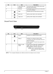
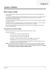
... remove/install the card. Lights up when Num Lock is closed 6 Chapter 1 Charging: The light shows amber when the battery is active. Indicates when the hard disk drive is charging. 2. Only one card can operate at any given time. NOTE: 1 The front panel indicators are visible even when the computer cover is activated. Fully charged: The light shows green when in AC mode. 2 Multi-in-1 card Accepts Secure Digital (SD), MultiMediaCard reader (MMC), Memory Stick (MS), Memory...
... remove/install the card. Lights up when Num Lock is closed 6 Chapter 1 Charging: The light shows amber when the battery is active. Indicates when the hard disk drive is charging. 2. Only one card can operate at any given time. NOTE: 1 The front panel indicators are visible even when the computer cover is activated. Fully charged: The light shows green when in AC mode. 2 Multi-in-1 card Accepts Secure Digital (SD), MultiMediaCard reader (MMC), Memory Stick (MS), Memory...

Service Guide
Page 24
... the hotkey combination. Turns the internal TouchPad on hotkeys. To activate hot keys, press and hold the key before pressing the other key in Sleep mode. Turns the display screen backlight off to access most of the computer's controls like screen brightness, volume output and the BIOS utility. Launches Acer ePower Management in Acer Empowering Technology. Switches display output between the display screen, external monitor (if connected) and both. Launches Acer eSettings Management in Acer Empowering Technology. Hot Keys The computer employs hotkeys or key...
... the hotkey combination. Turns the internal TouchPad on hotkeys. To activate hot keys, press and hold the key before pressing the other key in Sleep mode. Turns the display screen backlight off to access most of the computer's controls like screen brightness, volume output and the BIOS utility. Launches Acer ePower Management in Acer Empowering Technology. Switches display output between the display screen, external monitor (if connected) and both. Launches Acer eSettings Management in Acer Empowering Technology. Hot Keys The computer employs hotkeys or key...
Service Guide
Page 35
... not need to the Exit menu. • In any changes made and exit the BIOS Setup Utility. To activate the BIOS Utility, press F2 during POST to enter setup. Follow these instructions: • To choose a menu, use the left and right arrow keys. • To choose an item, use the up and down arrow keys. • To change boot device without entering BIOS Setup Utility, please set to Chapter 4 Troubleshooting when problem arises. If you can change boot device without entering BIOS SETUP Utility...
... not need to the Exit menu. • In any changes made and exit the BIOS Setup Utility. To activate the BIOS Utility, press F2 during POST to enter setup. Follow these instructions: • To choose a menu, use the left and right arrow keys. • To choose an item, use the up and down arrow keys. • To change boot device without entering BIOS Setup Utility, please set to Chapter 4 Troubleshooting when problem arises. If you can change boot device without entering BIOS SETUP Utility...

Service Guide
Page 36
... shows the CPU type and speed of the Optical device installed in software construction, standardized by the Open Software Foundation (OSF) as part of your reference only. This field shows the model name of the system. This field displays the asset tag number of the system. Information M a i n PhoenixBIOS Setup Utility Security Boot Exit CPU Type CPU Speed HDD Model Name: HDD Serial Number: ATAPI Model Name: System BIOS Version: VGA BIOS Version: Serial Number: Asset Tag Number: Product...
... shows the CPU type and speed of the Optical device installed in software construction, standardized by the Open Software Foundation (OSF) as part of your reference only. This field shows the model name of the system. This field displays the asset tag number of the system. Information M a i n PhoenixBIOS Setup Utility Security Boot Exit CPU Type CPU Speed HDD Model Name: HDD Serial Number: ATAPI Model Name: System BIOS Version: VGA BIOS Version: Serial Number: Asset Tag Number: Product...

Service Guide
Page 39
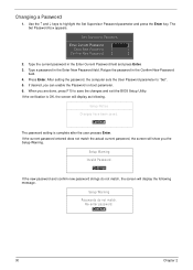
... the Enter key. Type a password in the Enter New Password and Confirm New Password fields. Type the current password in the "Confirm New Password" field. Chapter 2 29 Setting a Password Follow these steps: 1. Use the ↑ and ↓ keys to "Clear". 4. Use the ↑ and ↓ keys to "Set". 4. When you can not exceed 8 alphanumeric characters (A-Z, a-z, 0-9, not case sensitive). The password length can opt to save the changes and exit the BIOS Setup Utility. When you set the user...
... the Enter key. Type a password in the Enter New Password and Confirm New Password fields. Type the current password in the "Confirm New Password" field. Chapter 2 29 Setting a Password Follow these steps: 1. Use the ↑ and ↓ keys to "Clear". 4. Use the ↑ and ↓ keys to "Set". 4. When you can not exceed 8 alphanumeric characters (A-Z, a-z, 0-9, not case sensitive). The password length can opt to save the changes and exit the BIOS Setup Utility. When you set the user...
Service Guide
Page 40
... Setup Warning. Set Supervisor Password Enter Current Password [ ] Enter New Password [ ] Confirm New Password [ ] 2. When you can enable the Password on boot parameter. 6. The Set Password box appears. Changing a Password 1. Use the ↑ and ↓ keys to "Set". 5. After setting the password, the computer sets the User Password parameter to highlight the Set Supervisor Password parameter and press the Enter key. If desired, you are done, press F10 to save the changes and exit the BIOS Setup Utility. Setup Warning Invalid Password. [Continue] If the new password...
... Setup Warning. Set Supervisor Password Enter Current Password [ ] Enter New Password [ ] Confirm New Password [ ] 2. When you can enable the Password on boot parameter. 6. The Set Password box appears. Changing a Password 1. Use the ↑ and ↓ keys to "Set". 5. After setting the password, the computer sets the User Password parameter to highlight the Set Supervisor Password parameter and press the Enter key. If desired, you are done, press F10 to save the changes and exit the BIOS Setup Utility. Setup Warning Invalid Password. [Continue] If the new password...

Service Guide
Page 131
... Troubleshooting Chapter 4 Common Problems Use the following table with the verified symptom to determine which page to go to. Non-Acer products, prototype cards, or modified options can give false errors and invalid system responses. 1. Symptoms (Verified) Go To Power On Issue Page 122 No Display Issue Page 123 LCD Failure Page 125 Internal Keyboard Failure Page 125 TouchPad Failure Page 126 Internal...
... Troubleshooting Chapter 4 Common Problems Use the following table with the verified symptom to determine which page to go to. Non-Acer products, prototype cards, or modified options can give false errors and invalid system responses. 1. Symptoms (Verified) Go To Power On Issue Page 122 No Display Issue Page 123 LCD Failure Page 125 Internal Keyboard Failure Page 125 TouchPad Failure Page 126 Internal...

Service Guide
Page 133
...; Fans start up • Status LEDs light up If there is no power, see "Power On Issue" on this notebook model, switching between the internal display and the external display is still not resolved, see "Disassembly Process" on page 42). 8. Connect an external monitor to the computer and switch between the internal display and the external display is selected. Disconnect power and all external devices including port replicators or docking stations. Restart the computer. Remove the drives (see...
...; Fans start up • Status LEDs light up If there is no power, see "Power On Issue" on this notebook model, switching between the internal display and the external display is still not resolved, see "Disassembly Process" on page 42). 8. Connect an external monitor to the computer and switch between the internal display and the external display is selected. Disconnect power and all external devices including port replicators or docking stations. Restart the computer. Remove the drives (see...

Service Guide
Page 134
... lost, replace the cables. 4. NOTE: Ensure that : • The device is missing from the operating system DVD and follow the onscreen prompts. 11. Check the display resolution is listed under Other Devices. 9. b. Run a complete virus scan using up-to-date software to the previous version if updated. 7. Abnormal Video Display If video displays abnormally, perform the following actions one at the highest brightness setting, the LCD is still...
... lost, replace the cables. 4. NOTE: Ensure that : • The device is missing from the operating system DVD and follow the onscreen prompts. 11. Check the display resolution is listed under Other Devices. 9. b. Run a complete virus scan using up-to-date software to the previous version if updated. 7. Abnormal Video Display If video displays abnormally, perform the following actions one at the highest brightness setting, the LCD is still...

Service Guide
Page 138
... 4 The Install Windows screen displays. f. h. For more information see Windows Help and Support. 10. Remove any key to start to ensure the computer is set correctly. 7. For more information see Windows Help and Support. 9. b. c. Select the appropriate operating system, and click Next. Select Startup Repair. Run the Windows Memory Diagnostic Tool. Run Windows Check Disk by entering chkdsk /r from a known good date using up-to-date software to the operating system DVD. If the...
... 4 The Install Windows screen displays. f. h. For more information see Windows Help and Support. 10. Remove any key to start to ensure the computer is set correctly. 7. For more information see Windows Help and Support. 9. b. c. Select the appropriate operating system, and click Next. Select Startup Repair. Run the Windows Memory Diagnostic Tool. Run Windows Check Disk by entering chkdsk /r from a known good date using up-to-date software to the operating system DVD. If the...
Service Guide
Page 141
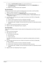
... the Enable DMA box is detected in "Hardware Specifications and Configurations" on the drive, motherboard, and cable connections. c. Turn off the power and remove the cover to inspect the connections to enter the BIOS Utility. 2. b. See "Disassembly Process" on page 42. Repeat for the other discs. Replace the ODD. Double-click IDE ATA/ATAPI controllers, then right-click ATA Device 0. c. See "Disassembly Process" on page 42. Reseat the drive ensuring and all cables are connected...
... the Enable DMA box is detected in "Hardware Specifications and Configurations" on the drive, motherboard, and cable connections. c. Turn off the power and remove the cover to inspect the connections to enter the BIOS Utility. 2. b. See "Disassembly Process" on page 42. Repeat for the other discs. Replace the ODD. Double-click IDE ATA/ATAPI controllers, then right-click ATA Device 0. c. See "Disassembly Process" on page 42. Reseat the drive ensuring and all cables are connected...

Service Guide
Page 143
... the mouse driver to verify mouse operation. Other Failures If the CRT Switch, Dock, LAN Port, external MIC or Speakers, PCI Express Card, 5-in-1 Card Reader or Volume Wheel fail, perform the following actions one at a time to correct the problem. 1. See the mouse user manual. 3. Remove any recently added software and reboot. 8. For more information see "Online Support Information" on page 177. Do not replace a non-defective FRUs: 1. Check Drive whether...
... the mouse driver to verify mouse operation. Other Failures If the CRT Switch, Dock, LAN Port, external MIC or Speakers, PCI Express Card, 5-in-1 Card Reader or Volume Wheel fail, perform the following actions one at a time to correct the problem. 1. See the mouse user manual. 3. Remove any recently added software and reboot. 8. For more information see "Online Support Information" on page 177. Do not replace a non-defective FRUs: 1. Check Drive whether...

Service Guide
Page 144
... to verify that all of the failure is detected, replace the FRU. If the problem does not recur, reconnect the removed devices one at the time of the following devices: • Non-Acer devices • Printer, mouse, and other external devices • Battery pack • Hard disk drive • DIMM • CD-ROM/Diskette drive Module • PC Cards 4. NOTE: Verify that have nothing to do not isolate...
... to verify that all of the failure is detected, replace the FRU. If the problem does not recur, reconnect the removed devices one at the time of the following devices: • Non-Acer devices • Printer, mouse, and other external devices • Battery pack • Hard disk drive • DIMM • CD-ROM/Diskette drive Module • PC Cards 4. NOTE: Verify that have nothing to do not isolate...

Service Guide
Page 146
... Description POST device initialization Check ROM copyright notice Check video configuration against CMOS Initialize PCI bus and devices Initialize all video adapters in system QuietBoot start (optional) Shadow video BIOS ROM Display BIOS copyright notice Display CPU type and speed Initialize EISA board Test keyboard Set key click if enabled Test for unexpected interrupts Initialize POST display service Display prompt "Press F2 to enter SETUP" Disable CPU cache Test RAM between 512 and 640 KB Test extended memory Test extended memory address lines...
... Description POST device initialization Check ROM copyright notice Check video configuration against CMOS Initialize PCI bus and devices Initialize all video adapters in system QuietBoot start (optional) Shadow video BIOS ROM Display BIOS copyright notice Display CPU type and speed Initialize EISA board Test keyboard Set key click if enabled Test for unexpected interrupts Initialize POST display service Display prompt "Press F2 to enter SETUP" Disable CPU cache Test RAM between 512 and 640 KB Test extended memory Test extended memory address lines...

Service Guide
Page 147
... Initialize Extended BIOS Data Area Test and initialize PS/2 mouse Initialize floppy controller Determine number of day Check key lock Initialize Typematic rate Erase F2 prompt Scan for F2 key stroke Enter SETUP Clear Boot flag Check for errors POST done - prepare to boot operating system One short beep before boot Terminate QuietBoot (optional) Check password (optional) Prepare Boot Initialize DMI parameters Initialize PnP Option ROMs Clear parity checkers Display MultiBoot menu Clear screen (optional) Check virus...
... Initialize Extended BIOS Data Area Test and initialize PS/2 mouse Initialize floppy controller Determine number of day Check key lock Initialize Typematic rate Erase F2 prompt Scan for F2 key stroke Enter SETUP Clear Boot flag Check for errors POST done - prepare to boot operating system One short beep before boot Terminate QuietBoot (optional) Check password (optional) Prepare Boot Initialize DMI parameters Initialize PnP Option ROMs Clear parity checkers Display MultiBoot menu Clear screen (optional) Check virus...

Service Guide
Page 189
... on indicator 6, 10 CPU Removing 78 Replacing 97 CPU Fan Removing 76 Replacing 98 D DIMM Modules Removing 49 Replacing 116 Display 4 display hotkeys 14 E EasyTouch Failure 132 Euro 15 External Module Disassembly Flowchart 43 F Features 1 Flash Utility 33 FPC Cable Removing 84 FRU (Field Replaceable Unit) List 145 H Hard Disk Drive Removing 52 Replacing 114 HDTV Switch Failure 133 Hibernation mode hotkey 14 Hot Keys 12 I Indicators 10 Intermittent Problems 134 Internal Speaker Failure 126 J Jumper and Connector Locations 139 K Keyboard Removing 56 Replacing 113 Keyboard Failure 125 L LCD Bezel...
... on indicator 6, 10 CPU Removing 78 Replacing 97 CPU Fan Removing 76 Replacing 98 D DIMM Modules Removing 49 Replacing 116 Display 4 display hotkeys 14 E EasyTouch Failure 132 Euro 15 External Module Disassembly Flowchart 43 F Features 1 Flash Utility 33 FPC Cable Removing 84 FRU (Field Replaceable Unit) List 145 H Hard Disk Drive Removing 52 Replacing 114 HDTV Switch Failure 133 Hibernation mode hotkey 14 Hot Keys 12 I Indicators 10 Intermittent Problems 134 Internal Speaker Failure 126 J Jumper and Connector Locations 139 K Keyboard Removing 56 Replacing 113 Keyboard Failure 125 L LCD Bezel...

Service Guide
Page 190
... Replacing 99 media access on indicator 6, 10 Memory Removing 49 Replacing 116 Memory Check 122 Model Definition 160 N No Display Issue 123 Notebook Manager hotkey 14 num lock on indicator 6, 10 O 180 ODD Failure 129 Online Support Information 177 Optical Disk Drive Replacing 117 Optical Drive Module Removing 47 P Panel 5 Bottom 8 PC Card 10 Power Board Removing 65 Replacing 104 Power On Failure 122 R Right Speaker Module Removing 68 Replacing 102 RTC Battery Removing 73 S SD Dummy Card Removing 45 Replacing 118 Speakers Removing 66, 68 speakers hotkey 14 Switch Cover Removing 55 Replacing...
... Replacing 99 media access on indicator 6, 10 Memory Removing 49 Replacing 116 Memory Check 122 Model Definition 160 N No Display Issue 123 Notebook Manager hotkey 14 num lock on indicator 6, 10 O 180 ODD Failure 129 Online Support Information 177 Optical Disk Drive Replacing 117 Optical Drive Module Removing 47 P Panel 5 Bottom 8 PC Card 10 Power Board Removing 65 Replacing 104 Power On Failure 122 R Right Speaker Module Removing 68 Replacing 102 RTC Battery Removing 73 S SD Dummy Card Removing 45 Replacing 118 Speakers Removing 66, 68 speakers hotkey 14 Switch Cover Removing 55 Replacing...


