

Service Guide
Page 7
Table of Contents System Specifications 1 Features 1 System Block Diagram 4 Your Acer Notebook tour 5 Front View 5 Closed Front View 6 Rear View 7 Left ...Specifications and Configurations 17 System Utilities 25 BIOS Setup Utility 25 Navigating the BIOS Utility 25 eMachines E627 BIOS 26 Information 26 Main 27 Security 28 Boot 31 Exit 32 BIOS Flash Utilities ...42 Disassembly Process 42 External Module Disassembly Process 43 External Modules Disassembly Flowchart 43 Removing the Battery Pack 44 Removing the SD Dummy Card 45 Removing the Lower Covers 46 Removing the Optical...
Table of Contents System Specifications 1 Features 1 System Block Diagram 4 Your Acer Notebook tour 5 Front View 5 Closed Front View 6 Rear View 7 Left ...Specifications and Configurations 17 System Utilities 25 BIOS Setup Utility 25 Navigating the BIOS Utility 25 eMachines E627 BIOS 26 Information 26 Main 27 Security 28 Boot 31 Exit 32 BIOS Flash Utilities ...42 Disassembly Process 42 External Module Disassembly Process 43 External Modules Disassembly Flowchart 43 Removing the Battery Pack 44 Removing the SD Dummy Card 45 Removing the Lower Covers 46 Removing the Optical...

Service Guide
Page 8
...Removing the Left Speaker Module 66 Removing the Right Speaker Module 68 Removing the TouchPad Bracket 70 Removing the Mainboard 72 Removing the RTC Battery 73 Removing the Thermal Module 74 Removing the CPU Fan 76 Removing the CPU 78 LCD Module Disassembly Process 79 LCD Module Disassembly ...116 Replacing the DIMM Modules 116 Replacing the ODD Module 117 Replacing the Lower Covers 117 Replacing the SD Dummy Card 118 Replacing the Battery 119 Troubleshooting 121 Common Problems 121 Power On Issue 122 No Display Issue 123 Random Loss of BIOS Settings 124 LCD Failure 125 ...
...Removing the Left Speaker Module 66 Removing the Right Speaker Module 68 Removing the TouchPad Bracket 70 Removing the Mainboard 72 Removing the RTC Battery 73 Removing the Thermal Module 74 Removing the CPU Fan 76 Removing the CPU 78 LCD Module Disassembly Process 79 LCD Module Disassembly ...116 Replacing the DIMM Modules 116 Replacing the ODD Module 117 Replacing the Lower Covers 117 Replacing the SD Dummy Card 118 Replacing the Battery 119 Troubleshooting 121 Common Problems 121 Power On Issue 122 No Display Issue 123 Random Loss of BIOS Settings 124 LCD Failure 125 ...

Service Guide
Page 12
...Dimensions and Weight • 372.3mm x 246.5mm x 26.8mm/40.6mm with ID • Weight < than 3100g (15.6" LCD/6-cell battery/super-multi ODD) Communication • Wireless • 802.11b/g/n WLAN/WiMax • Mini PCIE Wireless LAN module with with mini card slot • ... control • BIOS user, supervisor, HDD passwords • Kensington lock slot Power subsystem • 65W • Universal jack for adapter • Battery: 6-cell AS2009A Special keys and controls • 99-/100-/103-key keyboard • Supports Application keys for Windows XP/Linux version • Support ...
...Dimensions and Weight • 372.3mm x 246.5mm x 26.8mm/40.6mm with ID • Weight < than 3100g (15.6" LCD/6-cell battery/super-multi ODD) Communication • Wireless • 802.11b/g/n WLAN/WiMax • Mini PCIE Wireless LAN module with with mini card slot • ... control • BIOS user, supervisor, HDD passwords • Kensington lock slot Power subsystem • 65W • Universal jack for adapter • Battery: 6-cell AS2009A Special keys and controls • 99-/100-/103-key keyboard • Supports Application keys for Windows XP/Linux version • Support ...
Service Guide
Page 16
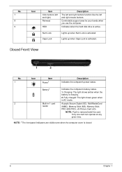
...Picture Card (xD). NOTE: Push to remove/install the card. Num Lock Caps Lock Lights up when Caps Lock is active. Battery1 Indicates the computer's battery status. 1. No. 7 8 9 Icon Item Click buttons (left and right) Palmrest HDD Description The left and right buttons function like the left and...the computer. Closed Front View 1 2 No. 1 Icon Item Power1 Description Indicates the computer's power status. Charging: The light shows amber when the battery is activated. NOTE: 1 The front panel indicators are visible even when the computer cover is closed 6 Chapter 1
...Picture Card (xD). NOTE: Push to remove/install the card. Num Lock Caps Lock Lights up when Caps Lock is active. Battery1 Indicates the computer's battery status. 1. No. 7 8 9 Icon Item Click buttons (left and right) Palmrest HDD Description The left and right buttons function like the left and...the computer. Closed Front View 1 2 No. 1 Icon Item Power1 Description Indicates the computer's power status. Charging: The light shows amber when the battery is activated. NOTE: 1 The front panel indicators are visible even when the computer cover is closed 6 Chapter 1
Service Guide
Page 18
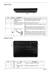
... security lock cable around an immovable object such as a table or handle of a locked drawer. Bottom View 1 2 6 3 5 4 No. 1 2 8 Icon Item Battery bay Battery release latch Description Houses the computer's battery pack. Releases the battery for removal. Right View 1 2 34 5 No. 1 2 3 4 5 Item Description Optical drive Optical disk access indicator Optical drive eject button Emergency eject...
... security lock cable around an immovable object such as a table or handle of a locked drawer. Bottom View 1 2 6 3 5 4 No. 1 2 8 Icon Item Battery bay Battery release latch Description Houses the computer's battery pack. Releases the battery for removal. Right View 1 2 34 5 No. 1 2 3 4 5 Item Description Optical drive Optical disk access indicator Optical drive eject button Emergency eject...

Service Guide
Page 19
No. 3 4 5 5 Icon Item Battery lock Hard disk bay Memory compartment Ventilation slots and cooling fan Description Locks the battery in position. Chapter 1 9 Note: Do not cover or obstruct the fan opening. Houses the computer's main memory. Enable the computer to stay cool, even after prolonged use. Houses the computer's hard disk (secured with screws).
No. 3 4 5 5 Icon Item Battery lock Hard disk bay Memory compartment Ventilation slots and cooling fan Description Locks the battery in position. Chapter 1 9 Note: Do not cover or obstruct the fan opening. Houses the computer's main memory. Enable the computer to stay cool, even after prolonged use. Houses the computer's hard disk (secured with screws).
Service Guide
Page 20
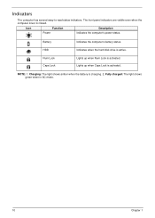
Charging: The light shows amber when the battery is active. Battery HDD Num Lock Caps Lock Indicates the computer's battery status. NOTE: 1. Icon Function Power Description Indicates the computer's power status. Indicates when the hard disk drive is charging. 2. Fully charged: The light shows green when in AC mode. 10 Chapter 1 Indicators The computer has several easy-to-read status indicators. Lights up when Caps Lock is activated. Lights up when Num Lock is activated. The front panel indicators are visible even when the computer cover is closed.
Charging: The light shows amber when the battery is active. Battery HDD Num Lock Caps Lock Indicates the computer's battery status. NOTE: 1. Icon Function Power Description Indicates the computer's power status. Indicates when the hard disk drive is charging. 2. Fully charged: The light shows green when in AC mode. 10 Chapter 1 Indicators The computer has several easy-to-read status indicators. Lights up when Caps Lock is activated. Lights up when Num Lock is activated. The front panel indicators are visible even when the computer cover is closed.

Service Guide
Page 32
... & model name Battery Type Pack capacity Normal Voltage Package configuration Specification 6 Cell SANYO/SONY/PANASONIC/SIMPLO AS2009A Li-ion 4400 mAh 2.2 Ah 3S2P LCD 15.6" Item Vendor/model ...
... & model name Battery Type Pack capacity Normal Voltage Package configuration Specification 6 Cell SANYO/SONY/PANASONIC/SIMPLO AS2009A Li-ion 4400 mAh 2.2 Ah 3S2P LCD 15.6" Item Vendor/model ...

Service Guide
Page 43
...: Do not install memory-related drivers (XMS, EMS, DPMI) when you use the AC adaptor power supply when you use the Phlash utility. If the battery pack does not contain enough power to run the Phlash utility. Copy the flash utilities to update the system BIOS flash ROM. Prepare a bootable diskette...
...: Do not install memory-related drivers (XMS, EMS, DPMI) when you use the AC adaptor power supply when you use the Phlash utility. If the battery pack does not contain enough power to run the Phlash utility. Copy the flash utilities to update the system BIOS flash ROM. Prepare a bootable diskette...

Service Guide
Page 52
...; LCD module disassembly The flowcharts provided in the succeeding disassembly sections illustrate the entire disassembly sequence. Unplug the AC adapter and all peripherals. 2. Remove the battery pack. Disassembly Process IMPORTANT: The LCD Module cannot be replaced.
...; LCD module disassembly The flowcharts provided in the succeeding disassembly sections illustrate the entire disassembly sequence. Unplug the AC adapter and all peripherals. 2. Remove the battery pack. Disassembly Process IMPORTANT: The LCD Module cannot be replaced.
Service Guide
Page 53
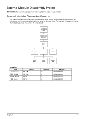
... the components that need to be removed during servicing. External Module Disassembly Process IMPORTANT: The outside housing and color may vary from system Rem ove Battery Rem ove Dummy Card Rem ove Lower Covers Rem ove ODD Rem ove DIMMs Screw List Step Lower Covers ODD Module WLAN Module HDD Carrier...
... the components that need to be removed during servicing. External Module Disassembly Process IMPORTANT: The outside housing and color may vary from system Rem ove Battery Rem ove Dummy Card Rem ove Lower Covers Rem ove ODD Rem ove DIMMs Screw List Step Lower Covers ODD Module WLAN Module HDD Carrier...
Service Guide
Page 54
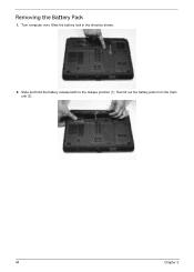
Slide and hold the battery release latch to the release position (1), then lift out the battery pack from the main unit (2). 2 1 44 Chapter 3 Turn computer over. Removing the Battery Pack 1. Slide the battery lock in the direction shown. 2.
Slide and hold the battery release latch to the release position (1), then lift out the battery pack from the main unit (2). 2 1 44 Chapter 3 Turn computer over. Removing the Battery Pack 1. Slide the battery lock in the direction shown. 2.
Service Guide
Page 56
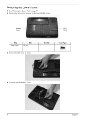
Remove the HDD cover as shown. See "Removing the Battery Pack" on page 44. 2. Memory Cover HDD Cover Step Lower Covers Size M2.5*8 3. Remove the three screws securing the Memory and HDD Covers. Quantity 3 Screw Type 4. Carefully open the Memory Cover. 46 Chapter 3 Removing the Lower Covers 1.
Remove the HDD cover as shown. See "Removing the Battery Pack" on page 44. 2. Memory Cover HDD Cover Step Lower Covers Size M2.5*8 3. Remove the three screws securing the Memory and HDD Covers. Quantity 3 Screw Type 4. Carefully open the Memory Cover. 46 Chapter 3 Removing the Lower Covers 1.
Service Guide
Page 57
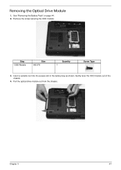
Insert a suitable tool into the access slot in the battery bay as shown. Removing the Optical Drive Module 1. See "Removing the Battery Pack" on page 44. 2. Step ODD Module Size M2.5*8 Quantity 1 Screw Type 3. Remove the screw securing the ODD module. Chapter 3 47 Pull the optical drive module out from the chassis. Gently lever the ODD module out of the chassis. 4.
Insert a suitable tool into the access slot in the battery bay as shown. Removing the Optical Drive Module 1. See "Removing the Battery Pack" on page 44. 2. Step ODD Module Size M2.5*8 Quantity 1 Screw Type 3. Remove the screw securing the ODD module. Chapter 3 47 Pull the optical drive module out from the chassis. Gently lever the ODD module out of the chassis. 4.

Service Guide
Page 64
... ove Power Board Rem ove Left Speaker Module Rem ove Right Speaker Module Rem ove TouchPad Bracket Lower Cover Rem ove Mainboard Rem ove RTC Battery Rem ove Thermal Module Rem ove CPU Fan Rem ove CPU Screw List Step LCD Module LCD Module Upper Cover Upper Cover Power Board Left...
... ove Power Board Rem ove Left Speaker Module Rem ove Right Speaker Module Rem ove TouchPad Bracket Lower Cover Rem ove Mainboard Rem ove RTC Battery Rem ove Thermal Module Rem ove CPU Fan Rem ove CPU Screw List Step LCD Module LCD Module Upper Cover Upper Cover Power Board Left...
Service Guide
Page 65
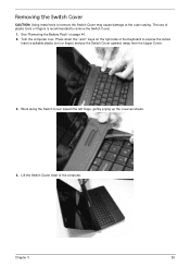
... the / and * keys on page 44. 2. Work along the Switch Cover toward the left hinge, gently prying up the cover as shown. 4. See "Removing the Battery Pack" on the right side of the computer. Insert a suitable plastic tool (or finger) and pry the Switch Cover upward, away from the Upper Cover...
... the / and * keys on page 44. 2. Work along the Switch Cover toward the left hinge, gently prying up the cover as shown. 4. See "Removing the Battery Pack" on the right side of the computer. Insert a suitable plastic tool (or finger) and pry the Switch Cover upward, away from the Upper Cover...
Service Guide
Page 83
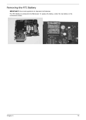
Removing the RTC Battery IMPORTANT:Follow local regulations for disposal of all batteries. The RTC Battery is soldered to the connections shown. Chapter 3 73 To replace the battery, solder the new battery to the Mainboard.
Removing the RTC Battery IMPORTANT:Follow local regulations for disposal of all batteries. The RTC Battery is soldered to the connections shown. Chapter 3 73 To replace the battery, solder the new battery to the Mainboard.
Service Guide
Page 129
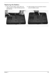
Slide and hold the battery release latch to secure the battery in the direction shown to the release position (1), insert the battery pack and press down (2). 2. Slide the battery lock in place. 2 1 Chapter 3 119 Replacing the Battery 1.
Slide and hold the battery release latch to secure the battery in the direction shown to the release position (1), insert the battery pack and press down (2). 2. Slide the battery lock in place. 2 1 Chapter 3 119 Replacing the Battery 1.

Service Guide
Page 133
...actions one at a time to the computer and switch between the internal display and the external display is by pressing Fn+F5 (on this notebook model, switching between the internal display and the external display is done by checking at least one until the failure point is no power, see... 42). 8. Drain any memory cards and CD/DVD discs. If the computer boots correctly, add the devices one by removing the power cable and battery and holding down the power button for specific model procedures. 2. Make sure that the internal display is still not resolved, see "Disassembly Process" on...
...actions one at a time to the computer and switch between the internal display and the external display is by pressing Fn+F5 (on this notebook model, switching between the internal display and the external display is done by checking at least one until the failure point is no power, see... 42). 8. Drain any memory cards and CD/DVD discs. If the computer boots correctly, add the devices one by removing the power cable and battery and holding down the power button for specific model procedures. 2. Make sure that the internal display is still not resolved, see "Disassembly Process" on...

Service Guide
Page 134
...right-click on page 177. 10. Readjust if necessary. 6. Random Loss of BIOS information, perform the following actions one year old, replace the CMOS battery. 2. See "Disassembly Process" on page 42. 4. c. If HDD information is virus free. 3. Run a complete virus scan using up-to-date ...the Issue is more than one at the highest brightness setting, the LCD is still not resolved, see "Online Support Information" on battery alone as this may be defective and should be replaced. 5. Click and drag the Resolution slider to the desired resolution. There are...
...right-click on page 177. 10. Readjust if necessary. 6. Random Loss of BIOS information, perform the following actions one year old, replace the CMOS battery. 2. See "Disassembly Process" on page 42. 4. c. If HDD information is virus free. 3. Run a complete virus scan using up-to-date ...the Issue is more than one at the highest brightness setting, the LCD is still not resolved, see "Online Support Information" on battery alone as this may be defective and should be replaced. 5. Click and drag the Resolution slider to the desired resolution. There are...


