Dell Latitude CPX Support Question
Dell Latitude CPX Support Question
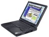
Find answers below for this question about Dell Latitude CPX - Notebook.Need a Dell Latitude CPX manual? We have 1 online manual for this item!
Question posted by aketuk on May 7th, 2013
My Display Window
My display window goes blank each time I use chrome
Current Answers
Related Dell Latitude CPX Manual Pages
Service Manual - Page 8

... angle of computer
support.dell.com
Dell Latitude CPt V/CPt S Series and CPx H/CPx J Series Service Manual
1
Unless otherwise ...display assembly when it is open nearly 180 degrees. Also, when performing the procedures in this manual assumes that you use a book or something similar to the bottom case should never be replaced by performing the removal procedure in your Dell Latitude...
Service Manual - Page 11

... each)
12.1-Inch Display Assembly Inverter:
M3.0 x 3 (3 each)
Palmrest Assembly: M2.5 x 20 (5 each)
System Board Assembly:
M2.5 x 4 (2 each) (w/o modem assembly)
M2.5 x 4 (1 each) M2.5 x 10 (1 each) (w/ modem assembly)
Microprocessor Shield Assembly:
3 captive and 2 removable screws
M2.0 x 3 (2 each)
M2.5 x 4 (1 each )
4
Dell Latitude CPt V/CPt S Series and CPx H/CPx J Series Service Manual...
Service Manual - Page 14

..., 12.1
12.1-inch display bezel
ASSY, BZL, LCD, 12.1
Display assembly screws SCR, M2.5x4, PHH, LP, ZPS
14.1-inch flex cable
ASSY, CBL, FLX, TFT
12.1-inch flex cable
ASSY, CBL, FLX, W/EXTN,12.1
14 14 16 16
14 16, 17
support.dell.com
Dell Latitude CPt V/CPt S Series and CPx H/CPx J Series Service...
Service Manual - Page 15

...ZPS
LCD hinge screw
SCR, M2.5X4, PHH, LP, ZPS
LCD bezel screw
SCR, M2.5X4, PHH, LP, ZPS
16, 18
Display latch assembly
ASSY, LATCH, SPR, DIS
14, 16
Bottom assembly
ASSY, CVR, BTM, BASE, PLSTC, CH-ST 22
Internal Modem (installed...
CUS, 192MB, DIMM, SDRAM
Customer kit, memory module, 256-MB
CUS, 256MB, DIMM, SDRAM
8
Dell Latitude CPt V/CPt S Series and CPx H/CPx J Series Service Manual
Service Manual - Page 17

display assembly
keyboard
palmrest assembly
hard-disk drive
internal modem (may not apply to your system)
system board
main battery
case plug for modem
bottom case assembly modular bay device
The following subsections provide instructions for removing and replacing field-replaceable parts and assemblies.
10 Dell Latitude CPt V/CPt S Series and CPx H/CPx J Series Service Manual
Service Manual - Page 19

... memory module cover. Insert a flat-blade screwdriver under the indentation in the bottom case assembly and lift the cover.
12 Dell Latitude CPt V/CPt S Series and CPx H/CPx J Series Service Manual Close the display, and turn the computer upside down on a flat work surface.
2.
Push the module latch toward the unlock icon. Keep holding...
Service Manual - Page 21

...the memory module socket. Remove the main battery and secondary battery (if present). 2. Close the display assembly, and turn the computer upside down until it .
4. Align the memory module's edge... down on a flat
work surface.
10-mm screws (7)
M2.5x10
14 Dell Latitude CPt V/CPt S Series and CPx H/CPx J Series Service Manual 2. With the module at a 45-degree angle, press the memory module...
Service Manual - Page 22

... a small flat-blade screwdriver under the edge of the blank key (see Figure 10), and lift the right edge of blank key
palmrest
6. Rotate the keyboard over the left side of...computer right-side up and open the display.
5. Rest the key face of the keyboard on the left edge of the palmrest. 7. support.dell.com
Dell Latitude CPt V/CPt S Series and CPx H/CPx J Series Service Manual 15 Remove ...
Service Manual - Page 27

... M2.5x4
1. NOTE: Always remove and replace the LCD panel as a complete assembly.
20 Dell Latitude CPt V/CPt S Series and CPx H/CPx J Series Service Manual Lift the display assembly from the connector on the bottom assembly (see Figure 13). 4. Open the display and disconnect the LCD flex cable from the bottom case assembly. Close the...
Service Manual - Page 28

Use a scribe to carefully pry the four rubber screw covers out of the four screw holes located at the top of the bezel on the front of the display assembly (see Figure 14). support.dell.com
Dell Latitude CPt V/CPt S Series and CPx H/CPx J Series Service Manual 21 rubber screw covers (4) 4-mm screws (6)
plastic screw covers...
Service Manual - Page 29

...Latitude CPt V/CPt S Series and CPx H/CPx J Series Service Manual 3. Remove the flex-cable retaining clip from the display...display-assembly hinge cover. 6. Remove the flex cable out from the display-assembly top cover. Remove the display assembly bezel. 2. Remove the LCD panel. 2. Separate the bezel from under the plastic strain relief retainer
located on a flat work surface. 3. Use...
Service Manual - Page 30

... retainer located on the back of the display-assembly hinge cover.
8. If your replacement...display assembly, allowing just enough space for the flex cable to the bottom of the hinge cover located at the bottom of the display-assembly top cover. display assembly bezel
bezel slot hinge tab
bezel clip bezel hinge
3. support.dell.com
Dell Latitude CPt V/CPt S Series and CPx H/CPx...
Service Manual - Page 31

...LCD panel in the display. Do not force the LCD flex cable into the connector. If you have trouble, check to the top cover.
24 Dell Latitude CPt V/CPt S Series and CPx H/CPx J Series Service Manual... Place the bottom edge of the LCD panel in the bottom of the top cover and
elevate the top of
the LCD panel. NOTE: Use ...
Service Manual - Page 32

... covers (4)
4-mm screws (6)
plastic screw covers (2)
display assembly bezel
5-mm screws (4) LCD panel
LCD flex cable
display-assembly top cover
back-light plug
latch inverter
ZIF connector...the connector on the left edge of the LCD panel. 4. support.dell.com
Dell Latitude CPt V/CPt S Series and CPx H/CPx J Series Service Manual 25 Disconnect the two-wire back-light plug from the top ...
Service Manual - Page 33

... opening .
5. Pry the hinge-cover assembly apart from the ZIF connector on the back of the display-assembly hinge cover.
3. Reinstall the 4-mm screw that is to be
installed.
26 Dell Latitude CPt V/CPt S Series and CPx H/CPx J Series Service Manual Find the manufacturer's name on the inverter. 2. Disconnect the LCD flex cable from...
Service Manual - Page 34

...cable (see Figure 18). The words Torisan and Sharp are used .
If you are installing a Sharp LCD panel, both ...be installed.
2.
support.dell.com
Dell Latitude CPt V/CPt S Series and CPx H/CPx J Series Service Manual 27 7.
The LCD flex cable...identical on top)
crease (underneath)
To replace the 12.1-inch display LCD panel inverter, perform the following steps:
1. Fold for more...
Service Manual - Page 36

... LCD panel. 5. If you can see Figure 14 and Figure 16). Remove the display assembly bezel latch by unsnapping the latch and
captive spring from the modular bay (if present). 3. 7. support.dell.com
Dell Latitude CPt V/CPt S Series and CPx H/CPx J Series Service Manual 29 Remove the main battery and secondary battery (if present...
Service Manual - Page 37

Remove the display assembly.
30 Dell Latitude CPt V/CPt S Series and CPx H/CPx J Series Service Manual Remove the keyboard.
4. Remove the main battery and secondary battery (if present). 2. The palmrest assembly consists of the touch pad and the palmrest.
20-mm screws (5)
M2.5x20
1. Remove the device from the modular bay (if present). 3.
Service Manual - Page 39

... (if present). 2. Carefully reposition the reserve battery EMI spring clip before securing the two 4-mm palmrest bracket screws.
32 Dell Latitude CPt V/CPt S Series and CPx H/CPx J Series Service Manual Remove the display assembly. 5. Remove the two 4-mm screws securing the palmrest bracket. Disconnect the reserve battery cable from the palmrest bracket as follows...
Service Manual - Page 40

Remove the display assembly. 4. Press the RJ11 connector of the modem assembly into the system board connector.
3.... connector for the modem
case plug for modem
M2.5x10
1. Remove the keyboard assembly. 3.
support.dell.com
Dell Latitude CPt V/CPt S Series and CPx H/CPx J Series Service Manual 33 Remove the main battery and secondary battery (if present). 2. The modem (if present)...
Similar Questions

On My Dell Laptop Latitude Cpx It Will Not Recognize The Primary Hard Disk Driv
(Posted by wright346 11 years ago)

My Dell Inspiron N5130 Can Not Turn On What Is The Problom
I installed the drivers and restart 32 bytes restart computer I saw that GrailI took out the battery...
I installed the drivers and restart 32 bytes restart computer I saw that GrailI took out the battery...
(Posted by Ralizada 11 years ago)

How Could I Fix The Alert Of Low C Drive Space?
Don't what program to delete to get more free space
Don't what program to delete to get more free space
(Posted by fbozasr 11 years ago)


My Notebook Laptop Dell Latitude H500gt Can' Type Word.
Hi , webmaster ,i can't type some character on keyboard Dell Latitude CPx H500GT, what do for resolv...
Hi , webmaster ,i can't type some character on keyboard Dell Latitude CPx H500GT, what do for resolv...
(Posted by vucaomai 12 years ago)