Icom IC-PW1 Support Question
Icom IC-PW1 Support Question
Find answers below for this question about Icom IC-PW1.Need a Icom IC-PW1 manual? We have 1 online manual for this item!
Question posted by setcomcast on August 26th, 2023
Band Switching Failed
PW1 is on160m. I switch (per hand) to 80m. After pusching PPT, PW1 goes to failure. Switching now to 40m or other Bands and back to 80m, it works. Switching from160m to 40m or other Bands and back to 80m, it works too.Is there any help, on the world ?73 dj4mt
Current Answers
Answer #1: Posted by SonuKumar on August 26th, 2023 10:37 AM
SonuKumar

Member since:
May 9th, 2021 Points: 16,604,000

Member since:
May 9th, 2021 Points: 16,604,000
I understand that you are having a problem with your Icom IC-PW1. When you switch from 160m to 80m and press the PPT button, the radio goes into failure mode. However, if you switch to another band and then back to 80m, the radio works fine.
This sounds like a problem with the radio's 160m band. It is possible that there is a short circuit or other problem with the band's circuitry.
Here are a few things you can try to fix the problem:
Check the connections to the 160m band. Make sure that all of the connectors are properly seated and that there is no corrosion or damage.
Try cleaning the 160m band's contacts. Use a soft cloth and some rubbing alcohol to clean the contacts.
If the problem persists, you may need to have the radio serviced by a qualified technician.
I hope this helps!
Please respond to my effort to provide you with the best possible solution by using the "Acceptable Solution" and/or the "Helpful" buttons when the answer has proven to be helpful.
Regards,
Sonu
Your search handyman for all e-support needs!!
Answer #2: Posted by Hanna0809 on August 26th, 2023 3:33 AM
Hanna0809

Member since:
July 22nd, 2023 Points: 21,130
Member since:
July 22nd, 2023 Points: 21,130
It sounds like you're experiencing a specific issue with your Icom IC-PW1 amplifier's band switching. The behavior you described might be due to a technical glitch or a connection problem. Try checking the connections, cables, and connectors involved in the band switching process. If the issue persists, you might want to reach out to Icom's customer support or consult online forums for assistance from fellow radio enthusiasts who might have encountered similar problems.
Related Icom IC-PW1 Manual Pages
Instruction Manual - Page 1
INSTRUCTION MANUAL
HF/50 MHz ALL BAND 1 kW LINEAR AMPLIFIER
iPW1
Instruction Manual - Page 2
...cords may result in an electrical shock. This will obstruct heat dissipation. DO NOT operate the IC-PW1 before attempting to operate the lin- AVOID using or placing the linear amplifier or...dusty environments or in areas with the linear ampli-
fier or remote controller. The IC-PW1 cannot be damaged.
Touching the linear amplifier may cause fire or electrical shock....
Instruction Manual - Page 3
... 12 s Operation 13 s Antenna tuner operation 14 s Protection circuit 14
4 MAINTENANCE 15 s Troubleshooting 15
5 SPECIFICATIONS 16
UNPACKING
q
w
e r t yu
i
o
!0
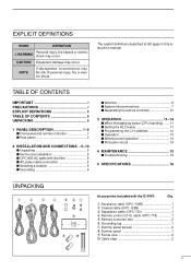
Accessories included with the IC-PW1:
Qty.
q Accessory cable (OPC-104B 1 w Coaxial cable (OPC-125B 1 e Separation cable (OPC-730 1 r Remote control (CI-V) cable (OPC-718 1 t Remote controller feet 2 y Grounding...
Instruction Manual - Page 4
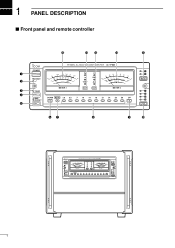
1 PANEL DESCRIPTION
s Front panel and remote controller
!5
!4 !3
!2
!1
HF/50MHz ALL BAND 1kW LINEAR AMPLIFIER
q w
POWER TRANSMIT
,
1P
8
*%
)05
"
5&.1
Po ID TEMP
VD SWR ALC
7%
483
"-$BE K
"-$
7
ʿ
1 2
INPUT
METER-1
METER-2
e
TUNER
1
r
2
AMP/ PROTECT
DOWN AUTO 1.8 3.5
7
10 ...
Instruction Manual - Page 5
...connectors or the IC-PW1's antenna tuner. t LINEAR AMPLIFIER SWITCH [AMP/PROTECT] Turns the linear amplifier ON and OFF. - o UPPER BAND SELECTOR [UP] (p. 13) Selects the higher operating band when pushed....transmission, a humming may sound depending on the 50 MHz band. • Goes out after 20 sec. While operating in the 50 MHz band, the antenna tuner does not start automatically. The [...
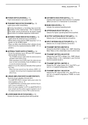
Instruction Manual - Page 6
...-
control level: 5.0 V DC/0.1 A -
DO NOT operate the IC-PW1 be used for transmit control.
These sockets can be separated by default ... is connected in parallel with [ACC-1] by the [EXCITER] switch. (!0)
e REMOTE CONTROLLER CABLE HOLE [CONTROLLER] (p. 10) Used for ...y CI-V REMOTE CONTROL JACKS [REMOTE] (pgs. 7-9) Used for band control with a PL-259 connector. This may damage the fi...
Instruction Manual - Page 7
...
4
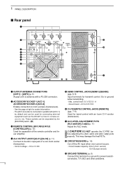
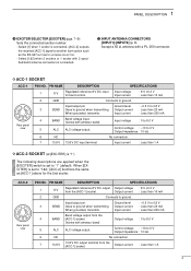
BAND
Band voltage input. (Varies with amateur band)
Output voltage : 0 to ground. Input current
: Less than 20 mA
When grounded, transmits.
Ground level
: -0.5 V to 0.8 V
3
SEND Goes to...[ACC-1] above for band control.
Output current : Less than 1 A
D ACC-2 SOCKET (w/[EXCITER] is "1")
The following descriptions are applied when the [EXCITER] switch is connected. [ACC...
Instruction Manual - Page 8
... line (200-240 V AC) q The green wire from TV sets, TV antenna elements, radios and other electro-magnetic sources. See p. 10 for the linear amplifier that enough length...CONNECTIONS
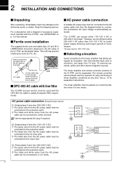
s Unpacking
After unpacking, immediately report any time.
For a description and a diagram of the IC-PW1 can be
connected to the AC cable as TVI, etc. s Ferrite core installation
The supplied ferrite...
Instruction Manual - Page 9
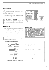
...the GROUND terminal and ground as short as shown at left.
s Antenna
For radio communications, the antenna is of critical importance, along with more than approx. ... of Voltage Standing Wave Ratio (VSWR) is tuned for a desired band. Strip the cable jacket and soft solder.
When using a lightning arrestor. The IC-PW1 has an SWR meter to monitor the antenna SWR continuously.
Low SWR ...
Instruction Manual - Page 10
...)
INPUT1
ANT1
ACC (13 pins)
REMOTE
Coaxial cable (supplied)
EXCITER
1
1&2
GND IC-706 series
GND
IC-PW1
AC outlet
(Non-Europe versions : 100-120/220-240 V
Europe version
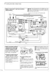
: 230 ...sure to connect the cable to the IC-PW1. 2 INSTALLATION AND CONNECTIONS
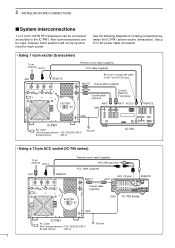
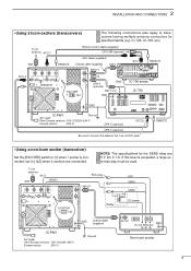
s System interconnections
1 or 2 Icom 100 W HF transceivers can be used, however, band selection will not be connected as exciters...
Instruction Manual - Page 11
...
SEND
EXCITER
1
1&2
Relay
DC power
GND
Coaxial cable (supplied)
IC-PW1
AC outlet
(Non-Europe versions : 100-120/220-240 V
Europe version
: 230 V)
Ground
RF OUT
GND DC OUT SEND ALC
Non-Icom exciter
8
REMOTE
• Using a non-Icom exciter (transceiver)
Set the [EXCITER] switch to [1&2] when 2 exciters are 5 V DC 0.1 A. set to [1] when...
Instruction Manual - Page 12
... must be used. nected to the 7-pin ACC(2) jack. When the jumper is set the jumper on the IC-PW1 controller to '2' to '2,' the CI-V control does not function even if an Icom exciter is con- 2 ...selector power to the ACC-1 socket
Supply the 13.8 V DC, 0.5 A to pin 7 of the IC-PW1 when the IC-PW1 power is OFF
In addition set to turn the controller's LEDs OFF as shown at right. nected to ...
Instruction Manual - Page 14
... in the same manner when a 2nd exciter is set incorrectly.
counterclockwise. (default)
[ALC adj2] [ALC adj1]
y Push the transmit meter-2 switch one or more times to select an operating band except 50 MHz band. - u Push [TUNER] to turn power ON.
-
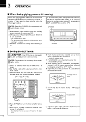
NOTE: Re-adjustment is complete. 3 OPERATION
s When first applying power (CPU resetting...
Instruction Manual - Page 15
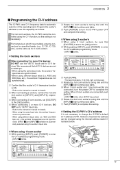
... transceivers which have multiple antenna connectors for specified bands (e.g. IC-726, IC-729, etc.), set the same as follows:
For non-Icom exciters, the IC-PW1 cannot be controlled using 1 Icom exciter
q While... address switch illustrated below. When using different baud rates (i.e. 4800 and 9600 bps, etc.), the exciters' frequencies are connected, turn the power OFF to turn the IC-PW1 power...
Instruction Manual - Page 16
...updated while scanning. NOTE: The band information is activated. 3 OPERATION
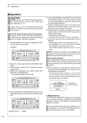
s Operation
CAUTION:
DO NOT operate the IC-PW1 before turning the IC-PW1 and other Icom CI-V transceivers: Turn the IC-781 power ON before adjusting the... the [INPUT1] connector. Temperature protection range
METER-1
D Band memory
The IC-PW1 stores ON/OFF settings for the antenna tuner and linear amplifier according ...
Instruction Manual - Page 17
...Europe version)
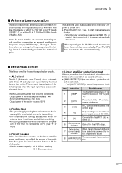
D Linear amplifier protection circuit
When a protection circuit is activated, a band indicator blinks to start automatically. Push [AMP/PROTECT] to tune the antenna manually.
to cancel... automatically after 20 sec.
Selected and When transmitting with different 7 current band's band selections between the lin-
D ALC circuit
The ALC (Automatic Level Control...
Instruction Manual - Page 18
...address.
p. 11
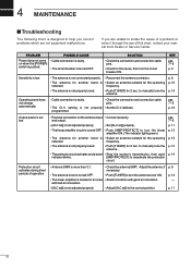
15 to manually tune the antenna.
• The protector circuit activates and a band • Stop the exciter's transmission, then push
indicator blinks.
[AMP/PROTECT] to manually tune... 7-9
p. 12
Output power is too low.
• Reverse connection on when the [POWER] switch is pushed.
• Cable connection is faulty. • The circuit breaker is not adjusted properly...
Instruction Manual - Page 19
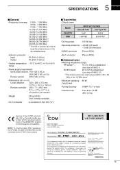
...ETS300 684 (EMC product standard for Commercially Available Amateur Radio Equipment). version can only be tuned within 1.80-1.95
MHz of the 1.8 MHz band.
• Minimum operating : 60 W input power
.../336/EEC directive for electrical safety.
Dec. 1998 Place and date of the IC-PW1 which display "CE" on the
24-28 MHz bands.
• Antenna connector :
Input
PL-239 × 2 (50 Ω...
Similar Questions

How Can I Open The Ic 7200 For Transmission On Marine Channels?
I have been adviced that it is possible to modify so that I for safety reasons only, can trx on mari...
I have been adviced that it is possible to modify so that I for safety reasons only, can trx on mari...
(Posted by Runeedamm 5 months ago)

My Icom Ic-2300h Can't Change Frequency,it's Only In 144mhz
(Posted by knightofthecentury 9 months ago)


Ic-pw1 Swr Meter Fault
My IC-PW1 fails to indicate SWR. The output power is OK on all bands and tuner works properly. All r...
My IC-PW1 fails to indicate SWR. The output power is OK on all bands and tuner works properly. All r...
(Posted by rw3xw 4 years ago)

Icom Ic-718 Switches Frequencies When Keying In Cw Mode
I was attempting to tune my 12 meter antenna and was using the built-in SWR meter. I set the frequen...
I was attempting to tune my 12 meter antenna and was using the built-in SWR meter. I set the frequen...
(Posted by ddennisberger 8 years ago)