User Manual
Page 3
... Customer Support and Service Unpacking Parts List Exploded View Remote Control Remote Control Battery Installation Description Features Power Installing the Monitor Ventilation Mounting the Monitor Desktop Installation Wall Mount Installation Connecting the Composite Video Signal to the Monitor Connecting the Y/C (S-Video) Signal to the Monitor Connecting the PC Signal to the Monitor Single / Multiple Monitor Configuration Navigating the Monitor Navigating the Front Panel Navigating the Monitor On-screen Display (OSD) On-screen Display Menus Custom Menu Picture / Sound Menu Setup Menu Table...
... Customer Support and Service Unpacking Parts List Exploded View Remote Control Remote Control Battery Installation Description Features Power Installing the Monitor Ventilation Mounting the Monitor Desktop Installation Wall Mount Installation Connecting the Composite Video Signal to the Monitor Connecting the Y/C (S-Video) Signal to the Monitor Connecting the PC Signal to the Monitor Single / Multiple Monitor Configuration Navigating the Monitor Navigating the Front Panel Navigating the Monitor On-screen Display (OSD) On-screen Display Menus Custom Menu Picture / Sound Menu Setup Menu Table...

User Manual
Page 5
... instructions. Use of controls or adjustments, or performance of IEC Publication 227 or IEC Publication 245. 10. Cleaning - Object and liquid entry - Power cord and plug protection - Heat Sources - For units intended to the unit from the wall outlet and disconnect the cable system. Bosch Security Systems, Inc. This will prevent damage to operate with 230 VAC, 50 Hz, the input and output power cord...
... instructions. Use of controls or adjustments, or performance of IEC Publication 227 or IEC Publication 245. 10. Cleaning - Object and liquid entry - Power cord and plug protection - Heat Sources - For units intended to the unit from the wall outlet and disconnect the cable system. Bosch Security Systems, Inc. This will prevent damage to operate with 230 VAC, 50 Hz, the input and output power cord...

User Manual
Page 8
... a third pin for any outdoor device connected to a ground source. - The installation for outdoor signals, especially regarding proper grounding of the mount and supporting structure, grounding of the coax to a discharge unit, size of grounding conductors, location of their working life, must be secured with one way. Disconnect the unit's input connectors from power and lightning conductors and transient protection, must...
... a third pin for any outdoor device connected to a ground source. - The installation for outdoor signals, especially regarding proper grounding of the mount and supporting structure, grounding of the coax to a discharge unit, size of grounding conductors, location of their working life, must be secured with one way. Disconnect the unit's input connectors from power and lightning conductors and transient protection, must...
User Manual
Page 9
... tested and found to take adequate measures. Units have power supplied whenever the power cord is inherent to other SELV circuits. General Purpose LCD Monitors Safety | en 5 PoE - Operation of the FCC Rules. and Canadian Models Only) This device complies with the limits for compliance, shall not be connected to digital video recording; If necessary, the user should only be made.
... tested and found to take adequate measures. Units have power supplied whenever the power cord is inherent to other SELV circuits. General Purpose LCD Monitors Safety | en 5 PoE - Operation of the FCC Rules. and Canadian Models Only) This device complies with the limits for compliance, shall not be connected to digital video recording; If necessary, the user should only be made.
User Manual
Page 12
....com More information For additional information, please contact your Bosch Security Systems representative or visit our web site at www.boschsecurity.com F.01U.127.338 | 2.0 | 2009.05 User's Manual Bosch Security Systems, Inc. 8 en | Safety 1.4 General Purpose LCD Monitors Customer Support and Service If this unit needs service, contact the nearest Bosch Security Systems Service Center for authorization to return and shipping instructions.
....com More information For additional information, please contact your Bosch Security Systems representative or visit our web site at www.boschsecurity.com F.01U.127.338 | 2.0 | 2009.05 User's Manual Bosch Security Systems, Inc. 8 en | Safety 1.4 General Purpose LCD Monitors Customer Support and Service If this unit needs service, contact the nearest Bosch Security Systems Service Center for authorization to return and shipping instructions.
User Manual
Page 13
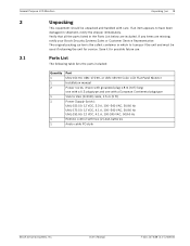
... 1 1 2 1 1 1 1 Part UML-151-90, UML-171-90, or UML-191-90 Color LCD Flat Panel Monitor Installation manual Power Cords, 3-wire with grounded plug 1.8 m (6 ft) long: one with a U.S plug type and one with a European Continental plug type VGA to VGA (D-SUB) cable, 1.5 m (5 ft) Power Supply (brick): UML-151-50: 12 VDC, 3.3 A, 100-240 VAC, 50/60 Hz UML-171-50: 12 VDC, 4.1 A, 100-240 VAC, 50/60 Hz UML-191-90: 12 VDC, 4.1 A, 100-240 VAC, 50/60 Hz Remote control with...
... 1 1 2 1 1 1 1 Part UML-151-90, UML-171-90, or UML-191-90 Color LCD Flat Panel Monitor Installation manual Power Cords, 3-wire with grounded plug 1.8 m (6 ft) long: one with a U.S plug type and one with a European Continental plug type VGA to VGA (D-SUB) cable, 1.5 m (5 ft) Power Supply (brick): UML-151-50: 12 VDC, 3.3 A, 100-240 VAC, 50/60 Hz UML-171-50: 12 VDC, 4.1 A, 100-240 VAC, 50/60 Hz UML-191-90: 12 VDC, 4.1 A, 100-240 VAC, 50/60 Hz Remote control with...

User Manual
Page 16
... 4.1 Remote Control Battery Placement 3. F.01U.127.338 | 2.0 | 2009.05 User's Manual Bosch Security Systems, Inc. Note: Replace batteries when required or at least once a year. Press this button to display AV1. MENU Displays the OSD. DOWN Moves the cursor down on the cover and slide it again. 4.1 Remote Control Battery Installation 1. AV2 Selects the AV2 mode. PC Selects the PC mode. APC (Auto Selects the Picture mode. Dispose of the Bosch remote control.
... 4.1 Remote Control Battery Placement 3. F.01U.127.338 | 2.0 | 2009.05 User's Manual Bosch Security Systems, Inc. Note: Replace batteries when required or at least once a year. Press this button to display AV1. MENU Displays the OSD. DOWN Moves the cursor down on the cover and slide it again. 4.1 Remote Control Battery Installation 1. AV2 Selects the AV2 mode. PC Selects the PC mode. APC (Auto Selects the Picture mode. Dispose of the Bosch remote control.
User Manual
Page 17
... openings on the rear of LCD monitors display PAL or NTSC standard color pictures in CCTV systems. Two (2) looping Composite Video BNC connector inputs and one (1) looping Y/C (S-Video) input using a 4-pin mini-DIN are not covered. General Purpose LCD Monitors Description | en 13 5 5.1 5.2 Description The Bosch General Purpose Family of the monitor are included with each works with Multiple Languages Power 6 6.1 Model No. VGA Input - A qualified service person should install the monitor and adhere to install the UML-151-90, UML...
... openings on the rear of LCD monitors display PAL or NTSC standard color pictures in CCTV systems. Two (2) looping Composite Video BNC connector inputs and one (1) looping Y/C (S-Video) input using a 4-pin mini-DIN are not covered. General Purpose LCD Monitors Description | en 13 5 5.1 5.2 Description The Bosch General Purpose Family of the monitor are included with each works with Multiple Languages Power 6 6.1 Model No. VGA Input - A qualified service person should install the monitor and adhere to install the UML-151-90, UML...
User Manual
Page 18
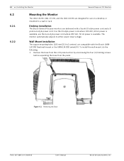
use on a desktop or mounted to either power input voltage. Wall Mount Installation The square mounting holes (100 mm [3.9 in.] centers) are delivered with the Bosch UMMLW-20B fixed wall mount or the UMM-LW-30B swivel/tilt. Remove the base from the LCD panel section by unscrewing the four (4) holding screws before separating the base from the panel. 14 en | Installing the Monitor General Purpose LCD Monitors 6.2 6.2.1 6.2.2 Mounting the Monitor The UML-151-90, UML-171-90, and the UML-191-90 are...
use on a desktop or mounted to either power input voltage. Wall Mount Installation The square mounting holes (100 mm [3.9 in.] centers) are delivered with the Bosch UMMLW-20B fixed wall mount or the UMM-LW-30B swivel/tilt. Remove the base from the LCD panel section by unscrewing the four (4) holding screws before separating the base from the panel. 14 en | Installing the Monitor General Purpose LCD Monitors 6.2 6.2.1 6.2.2 Mounting the Monitor The UML-151-90, UML-171-90, and the UML-191-90 are...
User Manual
Page 21
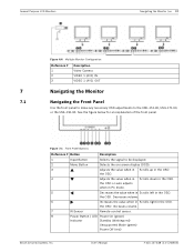
... OSD. the OSD. the OSD or auto adjusts when in PC mode. 5 Decreases the value when in Scrolls left in the OSD. See the figure below for an explanation of the front panel. Increases volume. 7 IR Sensor Remote control sensor. 8 Power Button / LED Power On (green) Indicator Standby (blinking red) Unsupported Mode (green) Power Off (red) Bosch Security Systems, Inc. Figure 7.1 Front Panel Buttons Reference # Button Description 1 Input Button Selects the signal to the UML-151-90, UML-171-90, or the UML-191-90...
... OSD. the OSD. the OSD or auto adjusts when in PC mode. 5 Decreases the value when in Scrolls left in the OSD. See the figure below for an explanation of the front panel. Increases volume. 7 IR Sensor Remote control sensor. 8 Power Button / LED Power On (green) Indicator Standby (blinking red) Unsupported Mode (green) Power Off (red) Bosch Security Systems, Inc. Figure 7.1 Front Panel Buttons Reference # Button Description 1 Input Button Selects the signal to the UML-151-90, UML-171-90, or the UML-191-90...
User Manual
Page 22
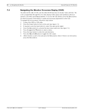
... the Monitor On-screen Display (OSD) The UML-151-90, UML-171-90, and the UML-191-90 have two (2) modes: Video and VGA. Press the Input button to select the appropriate signal. 4. To access the OSD menus, press the Menu button. Press the Power button to the OSD. Use the front panel of the monitor to make any necessary adjustments to turn on -screen display (OSD) menus and submenus where an operator can select operating parameters. F.01U.127.338 | 2.0 | 2009.05 User's Manual Bosch...
... the Monitor On-screen Display (OSD) The UML-151-90, UML-171-90, and the UML-191-90 have two (2) modes: Video and VGA. Press the Input button to select the appropriate signal. 4. To access the OSD menus, press the Menu button. Press the Power button to the OSD. Use the front panel of the monitor to make any necessary adjustments to turn on -screen display (OSD) menus and submenus where an operator can select operating parameters. F.01U.127.338 | 2.0 | 2009.05 User's Manual Bosch...

User Manual
Page 23
... Brightness, Contrast, Color, Tint, and the Sharpness level for video performance of the monitor. Set Up Enables user to Reset the factory default settings and to exit the OSD. When finished, press the Menu button to save any changes, then press the Menu button again to adjust the Language, OSD Tone, Blue Screen and Key Lock. Press the Menu button to increase or decrease the values. Press the left and right arrow buttons to access the OSD menu. Custom Brightness Contrast Color...
... Brightness, Contrast, Color, Tint, and the Sharpness level for video performance of the monitor. Set Up Enables user to Reset the factory default settings and to exit the OSD. When finished, press the Menu button to save any changes, then press the Menu button again to adjust the Language, OSD Tone, Blue Screen and Key Lock. Press the Menu button to increase or decrease the values. Press the left and right arrow buttons to access the OSD menu. Custom Brightness Contrast Color...

User Manual
Page 25
...50, Contrast = 60. Size (Video Mode) Selects the Aspect Ratio Control mode. Setup Reset Language OSD Tone Blue Screen Key Lock Firmware Version English Blue Off Off X.XX :Move :Input Table 7.5 Setup Menu :Menu Bosch Security Systems, Inc. Dynamic: Automatically adjusts the Brightness, Contrast, and Sharpness, maximizing the video quality in speaker output volume (range 0-100). Color Tone Selects the color temperature. Choices are applied. Volume Controls built-in the picture. Mode) Setup Menu To access the Setup menu, press the Menu button on the front panel of...
...50, Contrast = 60. Size (Video Mode) Selects the Aspect Ratio Control mode. Setup Reset Language OSD Tone Blue Screen Key Lock Firmware Version English Blue Off Off X.XX :Move :Input Table 7.5 Setup Menu :Menu Bosch Security Systems, Inc. Dynamic: Automatically adjusts the Brightness, Contrast, and Sharpness, maximizing the video quality in speaker output volume (range 0-100). Color Tone Selects the color temperature. Choices are applied. Volume Controls built-in the picture. Mode) Setup Menu To access the Setup menu, press the Menu button on the front panel of...

User Manual
Page 26
... of the monitor firmware. Power Management These monitors feature a power management system to "power down" upon receipt of the OSD. Adjusts the language of the display power management signaling (DPMS) from green to disable the key lock command. Enables or disables video loss indication. When key lock is detected. The power saving mode is active when the LED on the control button panel switches from a DPMS video card. 22 en | Power Management General Purpose LCD Monitors i 8 8.1 8.2 Submenu Reset Language Definition Restores default settings. The monitor enters...
... of the monitor firmware. Power Management These monitors feature a power management system to "power down" upon receipt of the OSD. Adjusts the language of the display power management signaling (DPMS) from green to disable the key lock command. Enables or disables video loss indication. When key lock is detected. The power saving mode is active when the LED on the control button panel switches from a DPMS video card. 22 en | Power Management General Purpose LCD Monitors i 8 8.1 8.2 Submenu Reset Language Definition Restores default settings. The monitor enters...
User Manual
Page 27
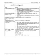
... either a resolution or timing mode that the Brightness and/or Contrast adjustments of the display have not been turned down key to select the Utility menu. "Check Input Signal" message is Adjust the Clock and Phase in its slot and the computer switched ON. General Purpose LCD Monitors Trouble Shooting Guide | en 23 9 Trouble Shooting Guide Problem Solution No image is displayed on the front panel of the monitor is securely connected into the wall outlet...
... either a resolution or timing mode that the Brightness and/or Contrast adjustments of the display have not been turned down key to select the Utility menu. "Check Input Signal" message is Adjust the Clock and Phase in its slot and the computer switched ON. General Purpose LCD Monitors Trouble Shooting Guide | en 23 9 Trouble Shooting Guide Problem Solution No image is displayed on the front panel of the monitor is securely connected into the wall outlet...
User Manual
Page 29
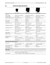
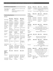
User's Manual F.01U.127.338 | 2.0 | 2009.05 General Purpose LCD Monitors 11 Technical Specifications Technical Specifications | en 25 Electrical Rated Voltage Voltage Range Power at Rated Voltage Sync Format LCD Panel Screen Size (H x V) Viewable Picture Area Pixel Pitch (H x V) Resolution Aspect Ratio Display Colors Response Time Backlight UML-151-90 UML-171-90 UML-191-90 120/230 VAC, 50/60 Hz 120/230 VAC, 50/60 Hz 120/230 VAC, 50/60 Hz 100-240 VAC 100-240 VAC...
User's Manual F.01U.127.338 | 2.0 | 2009.05 General Purpose LCD Monitors 11 Technical Specifications Technical Specifications | en 25 Electrical Rated Voltage Voltage Range Power at Rated Voltage Sync Format LCD Panel Screen Size (H x V) Viewable Picture Area Pixel Pitch (H x V) Resolution Aspect Ratio Display Colors Response Time Backlight UML-151-90 UML-171-90 UML-191-90 120/230 VAC, 50/60 Hz 120/230 VAC, 50/60 Hz 120/230 VAC, 50/60 Hz 100-240 VAC 100-240 VAC...

User Manual
Page 30
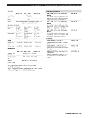
...button combination On-screen Display Video Mode PC Mode Input Source, Screen, OSD, Utility Input Screen, OSD, Color, Utility Indicators LED On-screen Power On (green) Standby (blinking red) Unsupported Mode (green) Power Off (red) VGA: Check input signal Video: Blue or black screen indicates video loss on AV1, AV2, or S-VIDEO. Connectors Video 1 (AV1) Composite video: two (2) BNC (1 in, 1 out) Video 2 (AV2) Composite video: two (2) BNC (1 in, 1 out) Y/C (S-video) Two (2) mini-DIN, 4-pin (1 in, 1 out) RGB One (1) VGA cable included Power Input 5.5 mm DC input jack Power Adapter Input...
...button combination On-screen Display Video Mode PC Mode Input Source, Screen, OSD, Utility Input Screen, OSD, Color, Utility Indicators LED On-screen Power On (green) Standby (blinking red) Unsupported Mode (green) Power Off (red) VGA: Check input signal Video: Blue or black screen indicates video loss on AV1, AV2, or S-VIDEO. Connectors Video 1 (AV1) Composite video: two (2) BNC (1 in, 1 out) Video 2 (AV2) Composite video: two (2) BNC (1 in, 1 out) Y/C (S-video) Two (2) mini-DIN, 4-pin (1 in, 1 out) RGB One (1) VGA cable included Power Input 5.5 mm DC input jack Power Adapter Input...
Brochure
Page 1
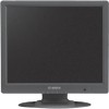
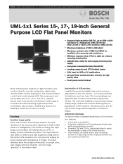
... display (LCD) flat-screen panel and are high-resolution color monitors ideal for use with analog video, digital video recorder (DVR), and PC applications. Each monitor also features a wide range of horizontal and vertical viewing angles that become progressively dimmer. The monitors' analog VGA input easily accommodates the widespread use the LCD monitor longer without the constant flickering that you get crisp, clear images with 15-in., 17-in., and 19-in CRT monitors. Key benefits of LCD monitors Long-life fluorescent backlights help...
... display (LCD) flat-screen panel and are high-resolution color monitors ideal for use with analog video, digital video recorder (DVR), and PC applications. Each monitor also features a wide range of horizontal and vertical viewing angles that become progressively dimmer. The monitors' analog VGA input easily accommodates the widespread use the LCD monitor longer without the constant flickering that you get crisp, clear images with 15-in., 17-in., and 19-in CRT monitors. Key benefits of LCD monitors Long-life fluorescent backlights help...
Brochure
Page 2
..., S-video, VGA Selects on-screen display (OSD), up cursor, down cursor/auto adjust, left cursor, right cursor On/Off Multiple push-button combination On-screen Display Video Mode PC Mode UML-151-90 UML-171-90 UML-191-90 Input Source, Screen, OSD, Utility Input Screen, OSD, Color, Utility Indicators LED On-screen UML-151-90 UML-171-90 UML-191-90 Power On (green) Standby (blinking red) Unsupported Mode (green) Power Off (red) VGA: Check input signal Video: Flashes "AV1" or "AV2" when there is a black screen Connectors UML-151-90 UML-171-90 UML-191-90 Video 1 (AV1) Composite video...
..., S-video, VGA Selects on-screen display (OSD), up cursor, down cursor/auto adjust, left cursor, right cursor On/Off Multiple push-button combination On-screen Display Video Mode PC Mode UML-151-90 UML-171-90 UML-191-90 Input Source, Screen, OSD, Utility Input Screen, OSD, Color, Utility Indicators LED On-screen UML-151-90 UML-171-90 UML-191-90 Power On (green) Standby (blinking red) Unsupported Mode (green) Power Off (red) VGA: Check input signal Video: Flashes "AV1" or "AV2" when there is a black screen Connectors UML-151-90 UML-171-90 UML-191-90 Video 1 (AV1) Composite video...
Brochure
Page 3
... x 1024 resolution, VGA, CVBS, audio, 120/230 VAC, 50/60 HZ UML-191-90 19-inch Color LCD Display Monitor 19-inch (483 mm) color LCD monitor, 3D image, 500 TVL, 1280 x 1024 resolution, VGA, CVBS, audio, 120/230 VAC, 50/60 HZ Accessories UMM-LW-20B Fixed Wall Mount Fixed wall mount for flat panel LCD monitors, black UMM-LW-30B Swivel/Tilt Wall Mount Swivel/Tilt wall mount for flat panel LCD monitors, black UMM-LCDUB-RM Rack Mount Bracket for LCD Monitors Supports dual 8.4-in a standard VESA rack cabinet UML-151-90 UML-171-90 UML-191-90 UMM...
... x 1024 resolution, VGA, CVBS, audio, 120/230 VAC, 50/60 HZ UML-191-90 19-inch Color LCD Display Monitor 19-inch (483 mm) color LCD monitor, 3D image, 500 TVL, 1280 x 1024 resolution, VGA, CVBS, audio, 120/230 VAC, 50/60 HZ Accessories UMM-LW-20B Fixed Wall Mount Fixed wall mount for flat panel LCD monitors, black UMM-LW-30B Swivel/Tilt Wall Mount Swivel/Tilt wall mount for flat panel LCD monitors, black UMM-LCDUB-RM Rack Mount Bracket for LCD Monitors Supports dual 8.4-in a standard VESA rack cabinet UML-151-90 UML-171-90 UML-191-90 UMM...


