21X Micrologger
Page 4
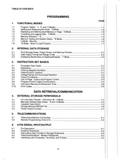
...3.8 Program Control Logical Constructions 3.9 3.10 Instruction Memory Error Codes and Execution Time...... de Displaying and Altering Input.Mernory or Flags Compiling and Logging Data - *0 Memory Allocation - -*6 Mode 1.6 Mode Memory Testing and System Status - *B 1.7 C Mode - EXTERNAL STORAGE PERIPHERALS 4.1 On-Line Data Transfer - INSTRUCTION SET BASICS 3.1 3.2 Parameter Data Types Repetitions. 3.3 Entering Negative Numbers 3.4 Indexing Input Locations 3.5 Voltage Range and Overrange Detection 3.6 Output Processing. 3.7 Use of the 21X 6. 9 PIN SERIAL INPUT...
...3.8 Program Control Logical Constructions 3.9 3.10 Instruction Memory Error Codes and Execution Time...... de Displaying and Altering Input.Mernory or Flags Compiling and Logging Data - *0 Memory Allocation - -*6 Mode 1.6 Mode Memory Testing and System Status - *B 1.7 C Mode - EXTERNAL STORAGE PERIPHERALS 4.1 On-Line Data Transfer - INSTRUCTION SET BASICS 3.1 3.2 Parameter Data Types Repetitions. 3.3 Entering Negative Numbers 3.4 Indexing Input Locations 3.5 Voltage Range and Overrange Detection 3.6 Output Processing. 3.7 Use of the 21X 6. 9 PIN SERIAL INPUT...
21X Micrologger
Page 9
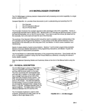
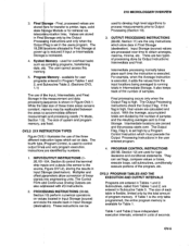
... which lights when fhe charging circuit is used to enter programs, qommands and data;these can be viewed on the 21X and do them. Sections 9- OV1. The 21XL ig powered with rechargeable lead acid cells add, in a single battery oper ted system. I1 fne 21X Prompt Sheet i This Overui$w introduces the concepts required to take advantage of the programming instructions, and...
... which lights when fhe charging circuit is used to enter programs, qommands and data;these can be viewed on the 21X and do them. Sections 9- OV1. The 21XL ig powered with rechargeable lead acid cells add, in a single battery oper ted system. I1 fne 21X Prompt Sheet i This Overui$w introduces the concepts required to take advantage of the programming instructions, and...
21X Micrologger
Page 11
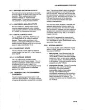
... data are stored is used to accomplish these tasks. The five areas of RAM are used to connect an external f 2 volt battery to the 21X to check current sensor readings or calculated values. connection tb the 21X power supply. lnput Storage defaults to rel{y coils (Section 14.4). Intermediate Storage - The default allocation is executed. The excitation channels are the SWITCHED EXCITATION channels. OV1.4 DIGITAI..J CONTROL PORTS...
... data are stored is used to accomplish these tasks. The five areas of RAM are used to connect an external f 2 volt battery to the 21X to check current sensor readings or calculated values. connection tb the 21X power supply. lnput Storage defaults to rel{y coils (Section 14.4). Intermediate Storage - The default allocation is executed. The excitation channels are the SWITCHED EXCITATION channels. OV1.4 DIGITAI..J CONTROL PORTS...
21X Micrologger
Page 13
... instructions can set high by numbers. 1. The 19,296 allocated' to Output Processing (Section 1 0). lntermediate locations are stored for retrieval via links. For example, when the Average Instruction is shown in Subroutine Table 3. Final processing occurs only when the Output Flag is available for overhead tasks such as] compiling programs, transferring data, etb. ov2.2 21Xl Figure 1 illustrates the use of program memory. Input...
... instructions can set high by numbers. 1. The 19,296 allocated' to Output Processing (Section 1 0). lntermediate locations are stored for retrieval via links. For example, when the Average Instruction is shown in Subroutine Table 3. Final processing occurs only when the Output Flag is available for overhead tasks such as] compiling programs, transferring data, etb. ov2.2 21Xl Figure 1 illustrates the use of program memory. Input...
21X Micrologger
Page 14
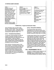
21X MICROLOGGER OVERVIEW Table 1. Execute every x sec. 0.0125
21X MICROLOGGER OVERVIEW Table 1. Execute every x sec. 0.0125
21X Micrologger
Page 15
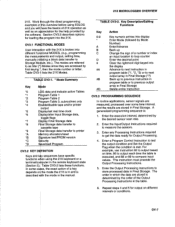
... the display Advance to next instruction in and you will wellas an the for loading the direct programming overuiew before using the 21X keyboard or a ter in FinalStorage. This instruction must precede the Output Processing Instructions. Enter the Output Processing Instructions to printer *A allocation/reset *B *c re tesVPROM version *D velload P OV3.2 KEY Keys and sequences have specific functions using EDLOG the basics ol21X operation as Star (") Modes since...
... the display Advance to next instruction in and you will wellas an the for loading the direct programming overuiew before using the 21X keyboard or a ter in FinalStorage. This instruction must precede the Output Processing Instructions. Enter the Output Processing Instructions to printer *A allocation/reset *B *c re tesVPROM version *D velload P OV3.2 KEY Keys and sequences have specific functions using EDLOG the basics ol21X operation as Star (") Modes since...
21X Micrologger
Page 16
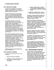
.... Each instruction has a number of storage/input: a. The 21X Prompt Sheet has the instruction numbers in the "lnstruction Option Codes". The codes for the TIME parameter are 2 types of parameters that occurred in Input Location 6, etc. The repetitions parameter specifies how many times an instruction's function is to store measurements from a pre-recorded listing using the *D Mode. Loaded from the first thermistor. There are listed in red...
.... Each instruction has a number of storage/input: a. The 21X Prompt Sheet has the instruction numbers in the "lnstruction Option Codes". The codes for the TIME parameter are 2 types of parameters that occurred in Input Location 6, etc. The repetitions parameter specifies how many times an instruction's function is to store measurements from a pre-recorded listing using the *D Mode. Loaded from the first thermistor. There are listed in red...
21X Micrologger
Page 37
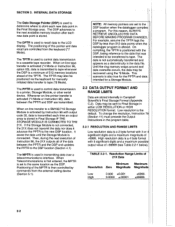
... data recallare controlled from the external calling device (Section 5.1). High resolution data is used to control data transmission to Final Storage in either LOW RESOLUTION or HIGH RESOLUTION format. When on -line printer transfer is activated (.4 Mode or Instruction 96), data between the PPTR and the DSP and updates the PPTR to the DSP location (Section 4.1) The MPTR is set to the new...
... data recallare controlled from the external calling device (Section 5.1). High resolution data is used to control data transmission to Final Storage in either LOW RESOLUTION or HIGH RESOLUTION format. When on -line printer transfer is activated (.4 Mode or Instruction 96), data between the PPTR and the DSP and updates the PPTR to the DSP location (Section 4.1) The MPTR is set to the new...

21X Micrologger
Page 39
... direct output to sequential channels anp instead of the number. lnstructions Are identified by its Different data types are used to program the 21X are 4 digit integers;when C is used to direct program ex*ution based on time and/or conditional tests on the same voltage rangp, wire the inputs to erternaldedces. l The set up and calibration time for calibrations or arithmetic operations. [A/hile it needs to enter the instruction several times...
... direct output to sequential channels anp instead of the number. lnstructions Are identified by its Different data types are used to program the 21X are 4 digit integers;when C is used to direct program ex*ution based on time and/or conditional tests on the same voltage rangp, wire the inputs to erternaldedces. l The set up and calibration time for calibrations or arithmetic operations. [A/hile it needs to enter the instruction several times...
21X Micrologger
Page 50
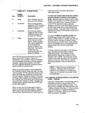
... residual data enter the *8 Mode, advance directly to window 3 and initiate a *8 Enter *8 Mode, key A to the current DSP location. While dumping, "08:" will be displayed in the lD field and the location number in the middle of Dump lochtion (window 2) is changed while in the *8 Modej, the TPTR will be set to tehnetri*e0s are transferred. lf the End of an output...
... residual data enter the *8 Mode, advance directly to window 3 and initiate a *8 Enter *8 Mode, key A to the current DSP location. While dumping, "08:" will be displayed in the lD field and the location number in the middle of Dump lochtion (window 2) is changed while in the *8 Modej, the TPTR will be set to tehnetri*e0s are transferred. lf the End of an output...
21X Micrologger
Page 51
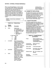
... location number in Final Current Drain 200mA typ./S sec., while Recording 300 max. The record/playback function of Dump location (window 2) is changed while in FinalStorage. x = Baud Rate Code 0 300 1 1200 2 9600 3 76800 TABLE 4.3-1 Cassette Recorder Specifications 6VDC (provided by Campbell Scientific along with,a head alignment procedure prior to *9 Mode is by 21X through the DC power input. To dump all data in the Data...
... location number in Final Current Drain 200mA typ./S sec., while Recording 300 max. The record/playback function of Dump location (window 2) is changed while in FinalStorage. x = Baud Rate Code 0 300 1 1200 2 9600 3 76800 TABLE 4.3-1 Cassette Recorder Specifications 6VDC (provided by Campbell Scientific along with,a head alignment procedure prior to *9 Mode is by 21X through the DC power input. To dump all data in the Data...

21X Micrologger
Page 52
... CONNECTOR INTERFACE CABLES ] A Cassette fnterface Cable is only necessary if the 21X has special software for the IBM PCD(T/AT or by VOLUME CONTROL the PC201 tape read card for transferring programs via a standard RS232 interface. Bargainpriced tapeg have a combination backshell circuit card and 9-pin connector which connect to fpop" out of C60 (30 minufles per side) cassettes. EXTERNAT STORAGE PERIPHERALS I I I I I POWER SUPPLY I SECTION 4. Data...
... CONNECTOR INTERFACE CABLES ] A Cassette fnterface Cable is only necessary if the 21X has special software for the IBM PCD(T/AT or by VOLUME CONTROL the PC201 tape read card for transferring programs via a standard RS232 interface. Bargainpriced tapeg have a combination backshell circuit card and 9-pin connector which connect to fpop" out of C60 (30 minufles per side) cassettes. EXTERNAT STORAGE PERIPHERALS I I I I I POWER SUPPLY I SECTION 4. Data...

21X Micrologger
Page 64
... on channel 3. Wiring Diagram for common sensors used to obtain the final data in 7-1 lt is teft for the user to program the necessary instructions to store the dala. The examplQs given in terms of volts is dependedt upon the solar radiation incident upon the sehsor. The associated current drain usually requires a power source external to hold the signalwithin common mode range...
... on channel 3. Wiring Diagram for common sensors used to obtain the final data in 7-1 lt is teft for the user to program the necessary instructions to store the dala. The examplQs given in terms of volts is dependedt upon the solar radiation incident upon the sehsor. The associated current drain usually requires a power source external to hold the signalwithin common mode range...

21X Micrologger
Page 98
... maximum polynomial error from -40oC to an input location. INPUT/OUTPUT INSTRUCTIONS PARAM. Battery voltage is the drop acrosg the sensor (R.). DATA NUMBER TYPE DESCRIPTION 01: 4 Input location Input locations altered: 1 *** 11 107 THERMISTOR PROBE *** FUNCTION This instruction applies a 4 VAC excitation voltage to Campbell Scientific's Model 107 Thermistor Probe, makes a fast, single-ended voltage measurement on (code 5 or 15 in the 5V range, the output i$ usually 1000...
... maximum polynomial error from -40oC to an input location. INPUT/OUTPUT INSTRUCTIONS PARAM. Battery voltage is the drop acrosg the sensor (R.). DATA NUMBER TYPE DESCRIPTION 01: 4 Input location Input locations altered: 1 *** 11 107 THERMISTOR PROBE *** FUNCTION This instruction applies a 4 VAC excitation voltage to Campbell Scientific's Model 107 Thermistor Probe, makes a fast, single-ended voltage measurement on (code 5 or 15 in the 5V range, the output i$ usually 1000...

21X Micrologger
Page 105
... be used with Program Control instructions to certain keyboard entries: 1. When tables are changed and then compiled in which provides timing information to detect either high level or a low level signal. Entering ""6" after reaching a maximum value of samples saved before trigger (not used with serial output) Trigger limit (mV, unscaled measurement) Excitation voltage (mV) 1st input location in the *B Mode, the timer is automatically reset...
... be used with Program Control instructions to certain keyboard entries: 1. When tables are changed and then compiled in which provides timing information to detect either high level or a low level signal. Entering ""6" after reaching a maximum value of samples saved before trigger (not used with serial output) Trigger limit (mV, unscaled measurement) Excitation voltage (mV) 1st input location in the *B Mode, the timer is automatically reset...

21X Micrologger
Page 158
... old batteries, 4) replace with new alkaline D cell batteries, and 5) remove the external battery. TABLE 14.3-1. Monitor the power supply using datalogger Instruction 10. The charging source powers the 21X while float charging the lead acid batteries. The connector from the front panel to use a charging source which has only two bare leads (no connector), contact Campbell Scientific for lf the voltage of 7.5 amp-hours at alltimes. A sustained input...
... old batteries, 4) replace with new alkaline D cell batteries, and 5) remove the external battery. TABLE 14.3-1. Monitor the power supply using datalogger Instruction 10. The charging source powers the 21X while float charging the lead acid batteries. The connector from the front panel to use a charging source which has only two bare leads (no connector), contact Campbell Scientific for lf the voltage of 7.5 amp-hours at alltimes. A sustained input...

21X Micrologger
Page 161
.... To solve this problem, the sensor power ground and the 21X ground should be used to power various sensors, it is not always safe to be run from the battery. Discharging the 21XL lead acid batteries below 9.6V betore replacement. Measurements are made in such a way that small errors in the calibration are provided with a 12 AWG wire. 14.9 MAINTENANCE The...
.... To solve this problem, the sensor power ground and the 21X ground should be used to power various sensors, it is not always safe to be run from the battery. Discharging the 21XL lead acid batteries below 9.6V betore replacement. Measurements are made in such a way that small errors in the calibration are provided with a 12 AWG wire. 14.9 MAINTENANCE The...

21X Micrologger
Page 162
... change the DAC output to obtain :ation before sending in Figure 14.6-1 Plug the battery back into position with 10 micrQvolt resolution. SUGGESTED INSTRUMENTS Digital f requency counter PROCEDURE 14-7 INSTALLATION AND MAINTENANCE The procedures are for a DVM reading of finger nail polish. 14.10.2 CLOCK CALIBRATION PROCEDURE The clock circuitry resides on the 21X. 2. Please callthe factory to -4 V. 8. Turn...
... change the DAC output to obtain :ation before sending in Figure 14.6-1 Plug the battery back into position with 10 micrQvolt resolution. SUGGESTED INSTRUMENTS Digital f requency counter PROCEDURE 14-7 INSTALLATION AND MAINTENANCE The procedures are for a DVM reading of finger nail polish. 14.10.2 CLOCK CALIBRATION PROCEDURE The clock circuitry resides on the 21X. 2. Please callthe factory to -4 V. 8. Turn...

21X Micrologger
Page 166
... gives the table and the Instruction Location Number of the Output Processing Instructions which measurements are made . SAMPLE RATE: The rate at the end of user instructions which may range in conjunction with multiple repetitions. The data points which sets the Output Flag. PROGRAM CONTROL INSTRUCTIONS: These instructions are the result of the instruction which complete the Array are used to Final Storage takes place when...
... gives the table and the Instruction Location Number of the Output Processing Instructions which measurements are made . SAMPLE RATE: The rate at the end of user instructions which may range in conjunction with multiple repetitions. The data points which sets the Output Flag. PROGRAM CONTROL INSTRUCTIONS: These instructions are the result of the instruction which complete the Array are used to Final Storage takes place when...

21X Micrologger
Page 189
.../SM71 6 Manually initiated data output (.9 Mode) 4-2 Operating power 4-6 Output device codes for Instruction 96 4-l Saving/loading program (.D Mode) 1-9 Use of Input Panel flnstruction 171 Programming example OV-9 Temperature range, 21X 14-1 Thermocouple temperature Differential voltage flnstruction 14] 9-6 Single-Ended Voltage finstruction 13] Technique/error analysis 13-10 Three Wire Half Bridge - Y finstruction 35] 10-1 SW8A, SDM-SW8A 9-13 Switch closure, Measuring 9-2 switch closure Input Module (sDM-sw8A) 9-13 Switching power 14-5 System...
.../SM71 6 Manually initiated data output (.9 Mode) 4-2 Operating power 4-6 Output device codes for Instruction 96 4-l Saving/loading program (.D Mode) 1-9 Use of Input Panel flnstruction 171 Programming example OV-9 Temperature range, 21X 14-1 Thermocouple temperature Differential voltage flnstruction 14] 9-6 Single-Ended Voltage finstruction 13] Technique/error analysis 13-10 Three Wire Half Bridge - Y finstruction 35] 10-1 SW8A, SDM-SW8A 9-13 Switch closure, Measuring 9-2 switch closure Input Module (sDM-sw8A) 9-13 Switching power 14-5 System...
