
AM16/32B Relay Multiplexer
Page 6
AM16/32B Relay Multiplexer 3 3-1. Diagram showing advancement of Contents 6.6 Thermocouple Measurement 30 6.6.1 Measurement Considerations 30 6.6.2 Single-ended Thermocouple Measurement 32 6.6.3 Differential Thermocouple Measurement ...program loops for external power supply 10 4-4. Wiring diagram for Windows program builder 12 5-2. Potentiometer hookup and measurement (using CABLE4CBL cable 11 5-1. AM16/32B aluminum cover plate 32 ii General Measurement Considerations 37 8. SCWin (Short Cut for strain gages and potentiometers (uses two CABLE4CBL cables 22 6-1....
AM16/32B Relay Multiplexer 3 3-1. Diagram showing advancement of Contents 6.6 Thermocouple Measurement 30 6.6.1 Measurement Considerations 30 6.6.2 Single-ended Thermocouple Measurement 32 6.6.3 Differential Thermocouple Measurement ...program loops for external power supply 10 4-4. Wiring diagram for Windows program builder 12 5-2. Potentiometer hookup and measurement (using CABLE4CBL cable 11 5-1. AM16/32B aluminum cover plate 32 ii General Measurement Considerations 37 8. SCWin (Short Cut for strain gages and potentiometers (uses two CABLE4CBL cables 22 6-1....
AM16/32B Relay Multiplexer
Page 9
... are directed to switch low level analog signals. v After wiring AM16/32B, exercise due care to multiplex power. Changing the setting of 30 mA will degrade the relay contacts involved, rendering that channel unsuitable for further low level analog measurement. Cautionary Notes The AM16/32B is to Campbell Scientific's SDM-CD16AC, A6REL-12, or A21REL-12 relays.
... are directed to switch low level analog signals. v After wiring AM16/32B, exercise due care to multiplex power. Changing the setting of 30 mA will degrade the relay contacts involved, rendering that channel unsuitable for further low level analog measurement. Cautionary Notes The AM16/32B is to Campbell Scientific's SDM-CD16AC, A6REL-12, or A21REL-12 relays.

AM16/32B Relay Multiplexer
Page 11
...differential analog sensors that can be measured by an AM16/32B depends primarily on the AM16/32B's top panel selects one of two modes of the sensor channels in the AM16/32B connect each with a second AM16/32B, up to multiplex sensors of sensors to 32 single-ended sensors that... The AM16/32B is to 16 single-ended or differential sensors that require only intermittent sampling). Most commonly, the AM16/32B is also possible to 16 six-wire full bridges (Section 6.5, Full Bridges with four lines a piece. It is used to a common output destined for Campbell Scientific's AM16/32A ...
...differential analog sensors that can be measured by an AM16/32B depends primarily on the AM16/32B's top panel selects one of two modes of the sensor channels in the AM16/32B connect each with a second AM16/32B, up to multiplex sensors of sensors to 32 single-ended sensors that... The AM16/32B is to 16 single-ended or differential sensors that require only intermittent sampling). Most commonly, the AM16/32B is also possible to 16 six-wire full bridges (Section 6.5, Full Bridges with four lines a piece. It is used to a common output destined for Campbell Scientific's AM16/32A ...
AM16/32B Relay Multiplexer
Page 12
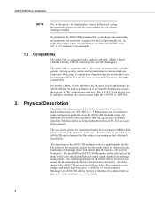
.../cleaning by sensor-datalogger compatibility. As long as nine individually insulated wires with Campbell's CR5000, CR800, CR850, CR3000, CR1000, CR23X, CR10(X), 21X, and CR7 dataloggers. The AM16/32B can also be used to multiplex up to the AM16/32B are provided so the AM16/32B can be fastened to 16 Geokon vibrating wire sensors through one or two...
.../cleaning by sensor-datalogger compatibility. As long as nine individually insulated wires with Campbell's CR5000, CR800, CR850, CR3000, CR1000, CR23X, CR10(X), 21X, and CR7 dataloggers. The AM16/32B can also be used to multiplex up to the AM16/32B are provided so the AM16/32B can be fastened to 16 Geokon vibrating wire sensors through one or two...
AM16/32B Relay Multiplexer
Page 13
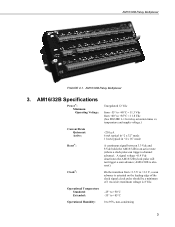
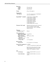
AM16/32B Relay Multiplexer FIGURE 2-1. AM16/32B Specifications Power*: Minimum Operating Voltage: Unregulated 12 Vdc from -55° to +40°C = 11.3 Vdc from +40° to +85°C = 11.8 Vdc (See FIGURE 3-1 for relay actuation times vs. AM16/32B Relay Multiplexer 3. temperature and supply voltage.) Current Drain Quiescent: Active: Reset*: Clock*:
AM16/32B Relay Multiplexer FIGURE 2-1. AM16/32B Specifications Power*: Minimum Operating Voltage: Unregulated 12 Vdc from -55° to +40°C = 11.3 Vdc from +40° to +85°C = 11.8 Vdc (See FIGURE 3-1 for relay actuation times vs. AM16/32B Relay Multiplexer 3. temperature and supply voltage.) Current Drain Quiescent: Active: Reset*: Clock*:
AM16/32B Relay Multiplexer
Page 14
.... AM16/32B Relay Multiplexer Dimensions Length: Width: Depth: 23.9 cm (9.4 in) 10.2 cm (4.0 in) 4.6 cm (1.8 in) Weight: 693 g (1.5 lb) (approx.) Mounting Tab Hole Spacing: 1 x 3 x 9 in or 3 mm diameter screws (see FIGURE 8-1). Refer to 1/8 in . Maximum Switching Current***: 500 mA Contact Specifications Initial contact resistance: Expandability** (nominal): 2 AM16/32Bs per CR800/CR850 4 AM16/32Bs per CR3000 4 AM16/32Bs per CR5000 4 AM16/32Bs...
.... AM16/32B Relay Multiplexer Dimensions Length: Width: Depth: 23.9 cm (9.4 in) 10.2 cm (4.0 in) 4.6 cm (1.8 in) Weight: 693 g (1.5 lb) (approx.) Mounting Tab Hole Spacing: 1 x 3 x 9 in or 3 mm diameter screws (see FIGURE 8-1). Refer to 1/8 in . Maximum Switching Current***: 500 mA Contact Specifications Initial contact resistance: Expandability** (nominal): 2 AM16/32Bs per CR800/CR850 4 AM16/32Bs per CR3000 4 AM16/32Bs per CR5000 4 AM16/32Bs...
AM16/32B Relay Multiplexer
Page 15
... channel is acceptable) will adversely affect the suitability of these relays to connect the control terminals. If your application requires additional multiplexing capability, please consult Campbell Scientific for switching currents in FIGURE 2-1. AM16/32B Relay Multiplexer Surge: Complies with IEC61000-4-5, test level 3 (±2 kV, 2 ohms coupling impedance) * Reset and clock protected by 8V varistors; +12V input...
... channel is acceptable) will adversely affect the suitability of these relays to connect the control terminals. If your application requires additional multiplexing capability, please consult Campbell Scientific for switching currents in FIGURE 2-1. AM16/32B Relay Multiplexer Surge: Complies with IEC61000-4-5, test level 3 (±2 kV, 2 ohms coupling impedance) * Reset and clock protected by 8V varistors; +12V input...

AM16/32B Relay Multiplexer
Page 16
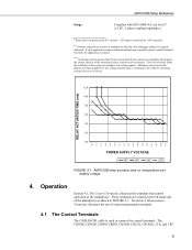
... GND 12V 4.1.1 Reset FIGURE 4-1. When this line drops lower than +0.9 Vdc, the multiplexer enters a quiescent, lowcurrent-drain state. AM16/32B Relay Multiplexer dataloggers connect to the AM16/32B as illustrated in FIGURE 4-1. AM16/32B to the 12 Vdc and " " terminals for power. A signal in Section 6, ...) is not available, an additional control port can be used to activate/deactivate the multiplexer when using CABLE4CBL cable With the 21X or CR7, the AM16/32B connects to datalogger power/control hookup using an Edlog datalogger; Measurement connections are connected to...
... GND 12V 4.1.1 Reset FIGURE 4-1. When this line drops lower than +0.9 Vdc, the multiplexer enters a quiescent, lowcurrent-drain state. AM16/32B Relay Multiplexer dataloggers connect to the AM16/32B as illustrated in FIGURE 4-1. AM16/32B to the 12 Vdc and " " terminals for power. A signal in Section 6, ...) is not available, an additional control port can be used to activate/deactivate the multiplexer when using CABLE4CBL cable With the 21X or CR7, the AM16/32B connects to datalogger power/control hookup using an Edlog datalogger; Measurement connections are connected to...
AM16/32B Relay Multiplexer
Page 17
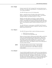
...COM terminals are switched to relay contacts. 4.1.2.2 Mode B To go directly to clock the multiplexer. A delay (typically 10 to 20 ms) is HI, relays are connected to the AM16/32B, Mode B allows one of two clocking modes: Mode A-sequentially advances through each relay ... • A CLK pulse occurs while RESET is HI. The AM16/32B operates in Mode A under the following circumstances: • RESET HI for 5 ms (±1 ms) without any clocking; AM16/32B Relay Multiplexer 4.1.2 Clock 4.1.2.1 Mode A NOTE Pulsing the AM16/32B "CLK" line high ("RES" line already high) advances the ...
...COM terminals are switched to relay contacts. 4.1.2.2 Mode B To go directly to clock the multiplexer. A delay (typically 10 to 20 ms) is HI, relays are connected to the AM16/32B, Mode B allows one of two clocking modes: Mode A-sequentially advances through each relay ... • A CLK pulse occurs while RESET is HI. The AM16/32B operates in Mode A under the following circumstances: • RESET HI for 5 ms (±1 ms) without any clocking; AM16/32B Relay Multiplexer 4.1.2 Clock 4.1.2.1 Mode A NOTE Pulsing the AM16/32B "CLK" line high ("RES" line already high) advances the ...
AM16/32B Relay Multiplexer
Page 18
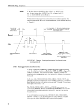
...Do (P86) with Delay (P22) configured for details. If several multiplexers are required, a CR5000, CR3000, CR800, CR850, CR1000, CR10(X), or CR23X control port can source sufficient current to drive up to six AM16/32B CLK or RES inputs wired in Section 5.3, General Programming Considerations). ...See Section 5.1, CRBasic Programming, for 5000 mV excitation). AM16/32B Relay Multiplexer NOTE If the time between the falling edge of the 5 ms...
...Do (P86) with Delay (P22) configured for details. If several multiplexers are required, a CR5000, CR3000, CR800, CR850, CR1000, CR10(X), or CR23X control port can source sufficient current to drive up to six AM16/32B CLK or RES inputs wired in Section 5.3, General Programming Considerations). ...See Section 5.1, CRBasic Programming, for 5000 mV excitation). AM16/32B Relay Multiplexer NOTE If the time between the falling edge of the 5 ms...
AM16/32B Relay Multiplexer
Page 19
...well being "topped off" by one of your datalogger operator's manual. 4.1.4 Power Supply The AM16/32B requires a continuous 12 Vdc power supply for example, datalogger, multiplexer, other peripherals, and sensors) at 12 Vdc when active (see current drain spec). An ...8-V, bi-polar transzorb connects shield ground to the multiplexer terminals labeled "12V" (+) and "GND". An AM16/32B COM terminal should also connect to datalogger power ground (see FIGURE 4-1). AM16/32B Relay Multiplexer ' ***** ' "Jump" AM16/32B directly to a datalogger ground terminal (" " or "G") via the...
...well being "topped off" by one of your datalogger operator's manual. 4.1.4 Power Supply The AM16/32B requires a continuous 12 Vdc power supply for example, datalogger, multiplexer, other peripherals, and sensors) at 12 Vdc when active (see current drain spec). An ...8-V, bi-polar transzorb connects shield ground to the multiplexer terminals labeled "12V" (+) and "GND". An AM16/32B COM terminal should also connect to datalogger power ground (see FIGURE 4-1). AM16/32B Relay Multiplexer ' ***** ' "Jump" AM16/32B directly to a datalogger ground terminal (" " or "G") via the...

AM16/32B Relay Multiplexer
Page 20
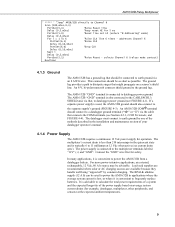
... 32 chan)/ 60 s) x 6 mA = 0.1 mA. For example, if a CR10X makes differential measurements on the AM16/32B are dedicated to the connection of sensors to the multiplexer (FIGURE 2-1). If a 21X power supply is started, the result will be inaccurate or overranged values. 4.2 Measurement Terminals ... to close before a measurement is used to power peripherals. Power and ground connections for the AM16/32B (FIGURE 4-3). AM16/32B Relay Multiplexer The average power required to operate an AM16/32B depends on the panel switch selection ("4x16" or "2x32" mode), the sensor input terminals are...
... 32 chan)/ 60 s) x 6 mA = 0.1 mA. For example, if a CR10X makes differential measurements on the AM16/32B are dedicated to the connection of sensors to the multiplexer (FIGURE 2-1). If a 21X power supply is started, the result will be inaccurate or overranged values. 4.2 Measurement Terminals ... to close before a measurement is used to power peripherals. Power and ground connections for the AM16/32B (FIGURE 4-3). AM16/32B Relay Multiplexer The average power required to operate an AM16/32B depends on the panel switch selection ("4x16" or "2x32" mode), the sensor input terminals are...
AM16/32B Relay Multiplexer
Page 21
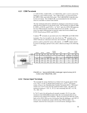
... the first clock pulse is received from one another. In "2x32" mode, the AM16/32B maintains an internal connection between ODD H and EVEN H and between ODD L and EVEN L. AM16/32B Relay Multiplexer 4.2.1 COM Terminals A CABLE3CBL, CABLE4CBL, or CABLE5CBL cable is used for the 4x16 mode.... The CABLE4CBL is typically used to connect the datalogger to the following table. In "4x16" mode the AM16/32B maintains the four COM terminals ...
... the first clock pulse is received from one another. In "2x32" mode, the AM16/32B maintains an internal connection between ODD H and EVEN H and between ODD L and EVEN L. AM16/32B Relay Multiplexer 4.2.1 COM Terminals A CABLE3CBL, CABLE4CBL, or CABLE5CBL cable is used for the 4x16 mode.... The CABLE4CBL is typically used to connect the datalogger to the following table. In "4x16" mode the AM16/32B maintains the four COM terminals ...
AM16/32B Relay Multiplexer
Page 22
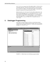
In "2x32" mode when the AM16/32B selects a given channel, the "H" sensor terminal is relay connected to both COM "H" terminals and the "L" sensor terminal is connected to both COM "L" terminals (COM ODD H ... the common terminals for Windows can be downloaded free of charge (www.campbellsci.com). SCWin can build many program configurations for Windows program builder) 12 AM16/32B Relay Multiplexer (1H, 1L, 2H, 2L) are connected with 32H, 32L. When the second clock pulse is received, the first SET is in "2x32" mode...
In "2x32" mode when the AM16/32B selects a given channel, the "H" sensor terminal is relay connected to both COM "H" terminals and the "L" sensor terminal is connected to both COM "L" terminals (COM ODD H ... the common terminals for Windows can be downloaded free of charge (www.campbellsci.com). SCWin can build many program configurations for Windows program builder) 12 AM16/32B Relay Multiplexer (1H, 1L, 2H, 2L) are connected with 32H, 32L. When the second clock pulse is received, the first SET is in "2x32" mode...
AM16/32B Relay Multiplexer
Page 23
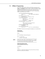
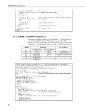
... is stored. NOTE PortSet must NOT be placed inside a conditional statement when running in Variable(I) END MEASUREMENT LOOP NextSubScan DEACTIVATE MULTIPLEXER Portset (1 ,0) 'Set C1 Low to disable Multiplexer The CRBasic instructions used . AM16/32B Relay Multiplexer 5.1 CRBasic Programming The CR5000, CR800, CR850, CR3000, and CR1000 are described below. Non-zero = Set port high. SubScan/NextSubScan...
... is stored. NOTE PortSet must NOT be placed inside a conditional statement when running in Variable(I) END MEASUREMENT LOOP NextSubScan DEACTIVATE MULTIPLEXER Portset (1 ,0) 'Set C1 Low to disable Multiplexer The CRBasic instructions used . AM16/32B Relay Multiplexer 5.1 CRBasic Programming The CR5000, CR800, CR850, CR3000, and CR1000 are described below. Non-zero = Set port high. SubScan/NextSubScan...
AM16/32B Relay Multiplexer
Page 24
... : SubScan(1,μSec,7) VoltDiff (Dest,2,mV5000,1,True,0,250,1.0,0) NextSubScan You will be measuring two differential sensors per instruction that are between SubScan() and NextSubScan. AM16/32B Relay Multiplexer Units: the unit of time to be used for the CR800 or CR850. A total of seven differential sensors are in the 4x16 configuration. The program...
... : SubScan(1,μSec,7) VoltDiff (Dest,2,mV5000,1,True,0,250,1.0,0) NextSubScan You will be measuring two differential sensors per instruction that are between SubScan() and NextSubScan. AM16/32B Relay Multiplexer Units: the unit of time to be used for the CR800 or CR850. A total of seven differential sensors are in the 4x16 configuration. The program...

AM16/32B Relay Multiplexer
Page 25
...) If IfTime (0,30,min)Then flag (1)=high If Flag(1)=high Then 'measure 48ea CS616 probes on AM16/32B in (4x16) mode PortSet (4,1) 'Set Mux Reset line High ' I=1 'set of AM16/32B terminals. AM16/32B Relay Multiplexer Wiring for CR1000 Program Example CR1000 AM16/32B (4x16) CS616* Control/Common Sensor Terminals C4 RES Odd H CS616#1_Green C5 CLK Odd L CS616...
...) If IfTime (0,30,min)Then flag (1)=high If Flag(1)=high Then 'measure 48ea CS616 probes on AM16/32B in (4x16) mode PortSet (4,1) 'Set Mux Reset line High ' I=1 'set of AM16/32B terminals. AM16/32B Relay Multiplexer Wiring for CR1000 Program Example CR1000 AM16/32B (4x16) CS616* Control/Common Sensor Terminals C4 RES Odd H CS616#1_Green C5 CLK Odd L CS616...
AM16/32B Relay Multiplexer
Page 26
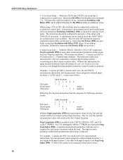
... side Sense wire return side 'CR5000 Example Program to measure 16 100 ohm Platinum Resistance Thermometers 'connected to an AM16/32B multiplexer used for 15 minute averages: DataTable (Avg15Min,1,-1) DataInterval (0,5,Min,10) Average (1,TRef,IEEE4,0) Average (6,TCTemp(),IEEE4,0)... CR5000 program, a similar program can be used in the 4x16 configuration. The program also measures 6 copper constantan thermocouples. AM16/32B Relay Multiplexer PulsePort (5,10000) 'Clock Mux CS616 (Period(I),3,1,6,3,1.0,0) 'measure 3ea CS616 probes I=I+3 NextSubScan ' For I=1 to 48 'convert CS616...
... side Sense wire return side 'CR5000 Example Program to measure 16 100 ohm Platinum Resistance Thermometers 'connected to an AM16/32B multiplexer used for 15 minute averages: DataTable (Avg15Min,1,-1) DataInterval (0,5,Min,10) Average (1,TRef,IEEE4,0) Average (6,TCTemp(),IEEE4,0)... CR5000 program, a similar program can be used in the 4x16 configuration. The program also measures 6 copper constantan thermocouples. AM16/32B Relay Multiplexer PulsePort (5,10000) 'Clock Mux CS616 (Period(I),3,1,6,3,1.0,0) 'measure 3ea CS616 probes I=I+3 NextSubScan ' For I=1 to 48 'convert CS616...

AM16/32B Relay Multiplexer
Page 27
...port low to measure the sensors are placed within the loop are executed before the program exits the loop. 17 AM16/32B Relay Multiplexer I=I+1 'The Resistance measurement measures the PRT resistance: Resistance (PRTResist(I),1,mV50,7,Ix1,1,500,True ,True ,0,250,0.01,0)...Loop Instruction Sequence When a number of similar sensors are multiplexed and measured, the Instructions to clock the AM16/32B and to deactivate AM16/32B #1, #9 Activate/Deactivate the AM16/32B - NextSubScan Portset (1 ,0) 'Set C1 Low to disable Multiplexer 'Calculate the Temperature from R/Ro: PRT (PRTTemp(1),...
...port low to measure the sensors are placed within the loop are executed before the program exits the loop. 17 AM16/32B Relay Multiplexer I=I+1 'The Resistance measurement measures the PRT resistance: Resistance (PRTResist(I),1,mV50,7,Ix1,1,500,True ,True ,0,250,0.01,0)...Loop Instruction Sequence When a number of similar sensors are multiplexed and measured, the Instructions to clock the AM16/32B and to deactivate AM16/32B #1, #9 Activate/Deactivate the AM16/32B - NextSubScan Portset (1 ,0) 'Set C1 Low to disable Multiplexer 'Calculate the Temperature from R/Ro: PRT (PRTTemp(1),...
AM16/32B Relay Multiplexer
Page 28
... 2 - 4 analog input channels. With the CR23X, CR10(X), 21X or CR7, instruction Step Loop Index (P90) is used to clock the AM16/32B if an excitation port is required to a sequentially assigned input location without overwriting any other with 3rd PROM). Example: 2 sensors per SET; P90...P22) can be measured by only one rep in their input locations. Loop count of 2. For example: 2 sensors per SET, 6 sensors total; AM16/32B Relay Multiplexer # 3 Clock and Delay - With the CR23X and CR10(X) the clock line is indexed. Instruction Do (P86) with Delay (P22) is not ...
... 2 - 4 analog input channels. With the CR23X, CR10(X), 21X or CR7, instruction Step Loop Index (P90) is used to clock the AM16/32B if an excitation port is required to a sequentially assigned input location without overwriting any other with 3rd PROM). Example: 2 sensors per SET; P90...P22) can be measured by only one rep in their input locations. Loop count of 2. For example: 2 sensors per SET, 6 sensors total; AM16/32B Relay Multiplexer # 3 Clock and Delay - With the CR23X and CR10(X) the clock line is indexed. Instruction Do (P86) with Delay (P22) is not ...