
CR200/CR200X-series Dataloggers
Page 5
... Pulse Sensors 7 2.1.10 Digital I/O Ports 8 2.1.11 RS-232 Sensors 9 2.2 Hands-on Exercise - Quickstart Tutorial 3 2.1 Primer - CR200(X) Data Acquisition 3 2.1.1 Components of Contents Section 1. Overview 23 3.1 CR200(X) Overview 23 3.1.1 Programmed Instructions Are Evaluated Sequentially 24 3.1.2 Sensor Support 25 3.1.3 Input / Output Interface: The Wiring Panel 25 3.1.4 Power ... 40 4.2.5 Self-Calibration 41 4.3 Bridge Resistance Measurements 41 4.3.1 Measurements Requiring AC Excitation 42 i Introduction 1 1.1 CR200(X) series Datalogger Models 1 Section 2.
... Pulse Sensors 7 2.1.10 Digital I/O Ports 8 2.1.11 RS-232 Sensors 9 2.2 Hands-on Exercise - Quickstart Tutorial 3 2.1 Primer - CR200(X) Data Acquisition 3 2.1.1 Components of Contents Section 1. Overview 23 3.1 CR200(X) Overview 23 3.1.1 Programmed Instructions Are Evaluated Sequentially 24 3.1.2 Sensor Support 25 3.1.3 Input / Output Interface: The Wiring Panel 25 3.1.4 Power ... 40 4.2.5 Self-Calibration 41 4.3 Bridge Resistance Measurements 41 4.3.1 Measurements Requiring AC Excitation 42 i Introduction 1 1.1 CR200(X) series Datalogger Models 1 Section 2.

CR200/CR200X-series Dataloggers
Page 6
... Measurement and Control Peripherals..49 5.1 Control Output ...49 5.1.1 Binary Control 49 5.2 Other Peripherals 51 5.2.1 TIMs...51 Section 6. CR200(X) Power Supply 53 6.1 Power Requirement 53 6.2 Calculating Power Consumption 53 6.3 Power Supplies...53 6.3.1 Battery Connection 53 Section 7. ...Measurement Reference 57 Section 8. Single-line Declarations 73 9.6.1 Variables 73 9.6.2 Constants 76 9.6.3 Alias and Unit Declarations 77 ii CR200(X) Configuration 59 8.1 DevConfig ...59 8.2 Sending the Operating System 60 8.2.1 Sending OS with DevConfig 60 8.3 Settings...62 8.3.1...
... Measurement and Control Peripherals..49 5.1 Control Output ...49 5.1.1 Binary Control 49 5.2 Other Peripherals 51 5.2.1 TIMs...51 Section 6. CR200(X) Power Supply 53 6.1 Power Requirement 53 6.2 Calculating Power Consumption 53 6.3 Power Supplies...53 6.3.1 Battery Connection 53 Section 7. ...Measurement Reference 57 Section 8. Single-line Declarations 73 9.6.1 Variables 73 9.6.2 Constants 76 9.6.3 Alias and Unit Declarations 77 ii CR200(X) Configuration 59 8.1 DevConfig ...59 8.2 Sending the Operating System 60 8.2.1 Sending OS with DevConfig 60 8.3 Settings...62 8.3.1...
CR200/CR200X-series Dataloggers
Page 9
... Battery 148 Section 18. Troubleshooting 151 18.1 Programming ...151 18.1.2 NAN and ±INF 153 18.2 Communications 154 18.2.1 RS-232 154 18.2.2 Communicating with CR200(X 27 E.2 Part 15 FCC Compliance Warning 27 E.2.1 Use of Contents Section 16. Serial Port Pin Outs 21 C.1 RS-232 Communications Port 21 C.1.1 Pin-Out...21...
... Battery 148 Section 18. Troubleshooting 151 18.1 Programming ...151 18.1.2 NAN and ±INF 153 18.2 Communications 154 18.2.1 RS-232 154 18.2.2 Communicating with CR200(X 27 E.2 Part 15 FCC Compliance Warning 27 E.2.1 Use of Contents Section 16. Serial Port Pin Outs 21 C.1 RS-232 Communications Port 21 C.1.1 Pin-Out...21...
CR200/CR200X-series Dataloggers
Page 10
... 48: Data from TrigVar Program 126 vi Table of Contents Index 29 List of Figures Figure 1: Data Acquisition System Components 3 Figure 2: CR200(X) Wiring Panel 5 Figure 3: Analog Sensor Wired to 40° C 40 Figure 28: Voltage Excitation Bridge Circuit 41 Figure 29: Switch...117 Figure 45: Input Sample Vectors 121 Figure 46: Mean Wind Vector 123 Figure 47: Standard Deviation of a Data Acquisition System 24 Figure 26: CR200(X) Wiring Panel 31 Figure 27: Voltage Measurement Accuracy (0° to Single-Ended Channel #1 6 Figure 4: Half Bridge Wiring -- Wind Vane Potentiometer 7...
... 48: Data from TrigVar Program 126 vi Table of Contents Index 29 List of Figures Figure 1: Data Acquisition System Components 3 Figure 2: CR200(X) Wiring Panel 5 Figure 3: Analog Sensor Wired to 40° C 40 Figure 28: Voltage Excitation Bridge Circuit 41 Figure 29: Switch...117 Figure 45: Input Sample Vectors 121 Figure 46: Mean Wind Vector 123 Figure 47: Standard Deviation of a Data Acquisition System 24 Figure 26: CR200(X) Wiring Panel 31 Figure 27: Voltage Measurement Accuracy (0° to Single-Ended Channel #1 6 Figure 4: Half Bridge Wiring -- Wind Vane Potentiometer 7...
CR200/CR200X-series Dataloggers
Page 11
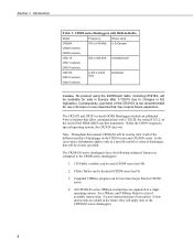
.... PakBus Link Performance Gage 137 Table 19. Measurement Instruction Syntax 84 CRBASIC EXAMPLE 13. CRBASIC Program Structure 72 Table 7. CR200(X) Telecommunications Options 131 Table 18. Load binary information into a single variable 71 CRBASIC EXAMPLE 3. Alias and Unit Declaration 77... 11. PC200W EZSetup Wizard Example Selections 12 Table 3. Current Sourcing Limits 38 Table 5. CR200 series Dataloggers with Built-In Radio 2 Table 2. Use of Variable Arrays to Campbell Scientific Equivalents 139 Table 20. Flag Declaration and Use 76 CRBASIC EXAMPLE 6.
.... PakBus Link Performance Gage 137 Table 19. Measurement Instruction Syntax 84 CRBASIC EXAMPLE 13. CRBASIC Program Structure 72 Table 7. CR200(X) Telecommunications Options 131 Table 18. Load binary information into a single variable 71 CRBASIC EXAMPLE 3. Alias and Unit Declaration 77... 11. PC200W EZSetup Wizard Example Selections 12 Table 3. Current Sourcing Limits 38 Table 5. CR200 series Dataloggers with Built-In Radio 2 Table 2. Use of Variable Arrays to Campbell Scientific Equivalents 139 Table 20. Flag Declaration and Use 76 CRBASIC EXAMPLE 6.

CR200/CR200X-series Dataloggers
Page 12
Programming for two data intervals in Expressions 153 viii Radio Power Minimization Program Examples 111 CRBASIC EXAMPLE 18. CRBASIC EXAMPLE. CRBASIC EXAMPLE. Two Rain Gages on a CR200(X) ...112 CRBASIC EXAMPLE 19. Using NAN in one data table 127 CRBASIC EXAMPLE 21. Using TrigVar to Trigger Data Storage 126 CRBASIC EXAMPLE 20. CRBASIC EXAMPLE. Table of Contents CRBASIC EXAMPLE 17.
Programming for two data intervals in Expressions 153 viii Radio Power Minimization Program Examples 111 CRBASIC EXAMPLE 18. CRBASIC EXAMPLE. CRBASIC EXAMPLE. Two Rain Gages on a CR200(X) ...112 CRBASIC EXAMPLE 19. Using NAN in one data table 127 CRBASIC EXAMPLE 21. Using TrigVar to Trigger Data Storage 126 CRBASIC EXAMPLE 20. CRBASIC EXAMPLE. Table of Contents CRBASIC EXAMPLE 17.

CR200/CR200X-series Dataloggers
Page 13
... beyond the Quickstart Tutorial (p. 3) or Overview (p. 23) sections. Section 1. You can email us at [email protected]. 1.1 CR200(X) series Datalogger Models Models CR200X and CR200 Dataloggers do not have a built-in -depth study requires other Campbell Scientific publications are unable to the tools you are available on-line at data acquisition. If you progressively deeper...
... beyond the Quickstart Tutorial (p. 3) or Overview (p. 23) sections. Section 1. You can email us at [email protected]. 1.1 CR200(X) series Datalogger Models Models CR200X and CR200 Dataloggers do not have a built-in -depth study requires other Campbell Scientific publications are unable to the tools you are available on-line at data acquisition. If you progressively deeper...
CR200/CR200X-series Dataloggers
Page 14
... (retired) 2.450 to 2.482 GHz Worldwide CR215 (retired) Caution No product using the 24XStream radio, including CR216X, will apply only to changes in the CR200-series and CR200X-series. See CRBasic and CRBasic Help for CR200series. 4. Section 1. In the cases where information applies only to a specific model or series of datalogger, that...
... (retired) 2.450 to 2.482 GHz Worldwide CR215 (retired) Caution No product using the 24XStream radio, including CR216X, will apply only to changes in the CR200-series and CR200X-series. See CRBasic and CRBasic Help for CR200series. 4. Section 1. In the cases where information applies only to a specific model or series of datalogger, that...

CR200/CR200X-series Dataloggers
Page 15
... part of the system can lead to "bad" data or no data. 2.1.1.1 How Programmed Instructions Are Evaluated The CR200(X) evaluates programmed instructions sequentially. A failure in FIGURE. APPENDIX. To acquire good data, suitable sensors and a reliable data... retrieval method are required. Quickstart Tutorial Quickstart tutorial gives a cursory look at CR200(X) data acquisition. 2.1 Primer - Figure 1: Data Acquisition System Components 2.1.1.2 Sensors Suitable sensors accurately and precisely transduce environmental change into...
... part of the system can lead to "bad" data or no data. 2.1.1.1 How Programmed Instructions Are Evaluated The CR200(X) evaluates programmed instructions sequentially. A failure in FIGURE. APPENDIX. To acquire good data, suitable sensors and a reliable data... retrieval method are required. Quickstart Tutorial Quickstart tutorial gives a cursory look at CR200(X) data acquisition. 2.1 Primer - Figure 1: Data Acquisition System Components 2.1.1.2 Sensors Suitable sensors accurately and precisely transduce environmental change into...

CR200/CR200X-series Dataloggers
Page 16
...facilitate data collection. Typically a base station radio that is near the PC, and the PC can measure most demanding applications. 2.1.2 CR200(X) Mounting The CR200(X) module integrates electronics within a compact housing, making it economical, small, and very rugged. 2.1.3 Wiring Panel As shown in ... laptop or PDA. Opening a terminal by prying the end may be stored. The CR200(X) uses spring-loaded terminal blocks for connecting sensors, power and communications devices. The CR200(X) will be the preferred method of devices, such as direct serial connection or infrared link...
...facilitate data collection. Typically a base station radio that is near the PC, and the PC can measure most demanding applications. 2.1.2 CR200(X) Mounting The CR200(X) module integrates electronics within a compact housing, making it economical, small, and very rugged. 2.1.3 Wiring Panel As shown in ... laptop or PDA. Opening a terminal by prying the end may be stored. The CR200(X) uses spring-loaded terminal blocks for connecting sensors, power and communications devices. The CR200(X) will be the preferred method of devices, such as direct serial connection or infrared link...

CR200/CR200X-series Dataloggers
Page 17
...powered by a nominal 12 volt DC source. Quickstart Tutorial Figure 2: CR200(X) Wiring Panel 2.1.4 Battery Backup A lithium battery backs up the CR200(X) clock, program, and memory if it loses power. 2.1.5 Power Supply The CR200(X) is a required component. Charging power can come from an external ...Section 2. Antennas are either 900 MHz or 2.4 GHz depending on the CR200(X) wiring panel for charging a 12 V lead-acid battery from a 16-22 VDC input such as a solar panel. 2.1.6 Antenna For CR200(X) models with a built-in charging regulator for antenna connection. Acceptable power...
...powered by a nominal 12 volt DC source. Quickstart Tutorial Figure 2: CR200(X) Wiring Panel 2.1.4 Battery Backup A lithium battery backs up the CR200(X) clock, program, and memory if it loses power. 2.1.5 Power Supply The CR200(X) is a required component. Charging power can come from an external ...Section 2. Antennas are either 900 MHz or 2.4 GHz depending on the CR200(X) wiring panel for charging a 12 V lead-acid battery from a 16-22 VDC input such as a solar panel. 2.1.6 Antenna For CR200(X) models with a built-in charging regulator for antenna connection. Acceptable power...

CR200/CR200X-series Dataloggers
Page 18
... Return voltage is illustrated in FIGURE. Resistance is determined by the CR200(X) returning from the bridge. 2.1.8.1 Voltage Excitation The CR200(X) supplies a precise excitation voltage via excitation terminals. The CR200(X) cannot perform differential voltage measurements. Half Bridge Wiring Wind Vane Potentiometer ...outputs are measured with respect to environmental change. Section 2. Analog sensors connect to ground (FIGURE. Because the CR200(X) cannot make the differential voltage readings used with the phenomena measured. Figure 3: Analog Sensor Wired to Single-Ended...
... Return voltage is illustrated in FIGURE. Resistance is determined by the CR200(X) returning from the bridge. 2.1.8.1 Voltage Excitation The CR200(X) supplies a precise excitation voltage via excitation terminals. The CR200(X) cannot perform differential voltage measurements. Half Bridge Wiring Wind Vane Potentiometer ...outputs are measured with respect to environmental change. Section 2. Analog sensors connect to ground (FIGURE. Because the CR200(X) cannot make the differential voltage readings used with the phenomena measured. Figure 3: Analog Sensor Wired to Single-Ended...

CR200/CR200X-series Dataloggers
Page 19
Figure 5: Pulse Input Types 7 A pulse input wiring example is shown in FIGURE. Note Period averaging sensors are illustrated in FIGURE. Quickstart Tutorial Figure 4: Half Bridge Wiring -- Anemometer Switch (p. 8). Wind Vane Potentiometer 2.1.9 Pulse Sensors The CR200(X) can measure switch closures, low-level AC signals (waveform breaks zero volts), or voltage pulses. Pulse Input Types (p. 7). Pulse Input Wiring -- Section 2. Compatible signal types are connected to analog channels.
Figure 5: Pulse Input Types 7 A pulse input wiring example is shown in FIGURE. Note Period averaging sensors are illustrated in FIGURE. Quickstart Tutorial Figure 4: Half Bridge Wiring -- Anemometer Switch (p. 8). Wind Vane Potentiometer 2.1.9 Pulse Sensors The CR200(X) can measure switch closures, low-level AC signals (waveform breaks zero volts), or voltage pulses. Pulse Input Types (p. 7). Pulse Input Wiring -- Section 2. Compatible signal types are connected to analog channels.

CR200/CR200X-series Dataloggers
Page 20
Anemometer Switch 2.1.10 Digital I/O Ports The CR200(X) has 2 digital I /O (p. 9), illustrates a simple application wherein a port is used to control a device while a second port monitors the state of the device. 8 Control and Monitoring with Digital I /O ports selectable, under program control, as binary inputs or control outputs. FIGURE. These are multi-function ports including: device driven interrupts, switch closure pulse counting, high frequency pulse counting, and SDI-12 communications. Quickstart Tutorial Figure 6: Pulse Input Wiring -- Section 2.
Anemometer Switch 2.1.10 Digital I/O Ports The CR200(X) has 2 digital I /O (p. 9), illustrates a simple application wherein a port is used to control a device while a second port monitors the state of the device. 8 Control and Monitoring with Digital I /O ports selectable, under program control, as binary inputs or control outputs. FIGURE. These are multi-function ports including: device driven interrupts, switch closure pulse counting, high frequency pulse counting, and SDI-12 communications. Quickstart Tutorial Figure 6: Pulse Input Wiring -- Section 2.

CR200/CR200X-series Dataloggers
Page 21
Use of RS-232 Port p. 10. Section 2. The port can be set up with Digital I/O 2.1.11 RS-232 Sensors The CR200(X) has an RS-232 input as defined in FIGURE. As indicated in the special S operating system. 9 Note: For the CR200, SerialInput () is a special instruction, which is available only in FIGURE. Location of RS-232 when Reading RS-232 Devices, p. 10 RS-232 sensors can be connected to the RS-232 port. Quickstart Tutorial Figure 7: Control and Monitoring with various baud rates, parity options, stop bit options, and so forth as shown in CRBASIC Help.
Use of RS-232 Port p. 10. Section 2. The port can be set up with Digital I/O 2.1.11 RS-232 Sensors The CR200(X) has an RS-232 input as defined in FIGURE. As indicated in the special S operating system. 9 Note: For the CR200, SerialInput () is a special instruction, which is available only in FIGURE. Location of RS-232 when Reading RS-232 Devices, p. 10 RS-232 sensors can be connected to the RS-232 port. Quickstart Tutorial Figure 7: Control and Monitoring with various baud rates, parity options, stop bit options, and so forth as shown in CRBASIC Help.

CR200/CR200X-series Dataloggers
Page 22
During the exercise, the following items will be described. • Attaching a temperature probe to analog differential terminals • Creating a program for the CR200(X) • Making a simple temperature measurement • Sending data from the CR200(X) to illustrate the function of RS-232 when Reading RS-232 Devices 2.2 Hands-on Exercise - Measuring Temperature This tutorial is designed to a PC • Viewing the data from the CR200(X) 10 Section 2. Quickstart Tutorial Figure 8: Location of RS-232 Port Figure 9: Use of the CR200(X).
During the exercise, the following items will be described. • Attaching a temperature probe to analog differential terminals • Creating a program for the CR200(X) • Making a simple temperature measurement • Sending data from the CR200(X) to illustrate the function of RS-232 when Reading RS-232 Devices 2.2 Hands-on Exercise - Measuring Temperature This tutorial is designed to a PC • Viewing the data from the CR200(X) 10 Section 2. Quickstart Tutorial Figure 8: Location of RS-232 Port Figure 9: Use of the CR200(X).
CR200/CR200X-series Dataloggers
Page 23
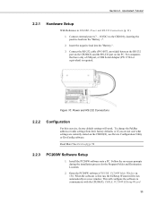
...for the Program Folder and Destination Location. 2. When the software is required. Follow the on the CR200(X), use Device Configuration Utility or DevConfig software. This will configure the software to the CR200 by inserting the positive lead into the "Battery-". 3. Connect external power (7 - 16VDC) to... the negative lead into the "Battery +". 2. Connect the RS-232 cable (PN 10873, provided) between the RS-232 port on the CR200(X) and the RS-232 port on the PC. Figure 10: Power and RS-232 Connections 2.2.2 Configuration For this exercise, factory default settings will...
...for the Program Folder and Destination Location. 2. When the software is required. Follow the on the CR200(X), use Device Configuration Utility or DevConfig software. This will configure the software to the CR200 by inserting the positive lead into the "Battery-". 3. Connect external power (7 - 16VDC) to... the negative lead into the "Battery +". 2. Connect the RS-232 cable (PN 10873, provided) between the RS-232 port on the CR200(X) and the RS-232 port on the PC. Figure 10: Power and RS-232 Connections 2.2.2 Configuration For this exercise, factory default settings will...
CR200/CR200X-series Dataloggers
Page 24
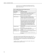
...tab is moved to the user. 12 Should this tutorial, accept the default settings. Communications Test A communications test between the software and CR200(X). This tab displays information on the currently selected datalogger along with clock and program functions. These access additional functions available to a different ... and introduction to the original port. The Monitor Data or Collect Data tabs may change the COM port to configure how the CR200(X) communicates through the wizard. Click on how to the next screen. This will be entered on "Edit Datalogger Setup" and ...
...tab is moved to the user. 12 Should this tutorial, accept the default settings. Communications Test A communications test between the software and CR200(X). This tab displays information on the currently selected datalogger along with clock and program functions. These access additional functions available to a different ... and introduction to the original port. The Monitor Data or Collect Data tabs may change the COM port to configure how the CR200(X) communicates through the wizard. Click on how to the next screen. This will be entered on "Edit Datalogger Setup" and ...

CR200/CR200X-series Dataloggers
Page 25
... touch and then allow them to create a program that measures air temperature (°C) with a 109 Temperature Probe, and rainfall (mm) with a TE525WS rain gage. The CR200(X) will use Short Cut to spring apart. 2.2.3.1.2 Procedure (Short Cut Steps 1-6) 1. Section 2. Quickstart Tutorial Figure 11: PC200W Main Window 2.2.3.1 Programming With Short Cut 2.2.3.1.1 Short Cut...
... touch and then allow them to create a program that measures air temperature (°C) with a 109 Temperature Probe, and rainfall (mm) with a TE525WS rain gage. The CR200(X) will use Short Cut to spring apart. 2.2.3.1.2 Procedure (Short Cut Steps 1-6) 1. Section 2. Quickstart Tutorial Figure 11: PC200W Main Window 2.2.3.1 Programming With Short Cut 2.2.3.1.1 Short Cut...
CR200/CR200X-series Dataloggers
Page 26
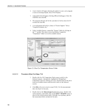
... to create a new program or open an existing program. A drop-down list will appear showing the option to the Selected sensors. 2. Select the CR200(X) and click OK. 4. Select "Campbell Scientific, Inc." 6. This shows several sub-folders. Expand the "Temperature" folder to 10 seconds and click OK. 5. A new window will appear showing different dataloggers...
... to create a new program or open an existing program. A drop-down list will appear showing the option to the Selected sensors. 2. Select the CR200(X) and click OK. 4. Select "Campbell Scientific, Inc." 6. This shows several sub-folders. Expand the "Temperature" folder to 10 seconds and click OK. 5. A new window will appear showing different dataloggers...