CR200/CR200X-series Dataloggers
Page 3
... Campbell Scientific, Inc. ("Campbell") to products manufactured by surface carrier prepaid within the continental United States of shipment unless otherwise specified in materials and workmanship under this warranty. Products not manufactured, but that are re-sold by Campbell, are warranted by the original manufacturer. Campbell's obligation under normal use and service for installation services performed by Campbell such as programming to customer specifications...
... Campbell Scientific, Inc. ("Campbell") to products manufactured by surface carrier prepaid within the continental United States of shipment unless otherwise specified in materials and workmanship under this warranty. Products not manufactured, but that are re-sold by Campbell, are warranted by the original manufacturer. Campbell's obligation under normal use and service for installation services performed by Campbell such as programming to customer specifications...
CR200/CR200X-series Dataloggers
Page 10
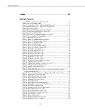
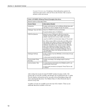
Anememeter Switch 8 Figure 7: Control and Monitoring with Digital I/O 9 Figure 8: Location of RS-232 Port 10 Figure 9: Use of RS-232 when Reading RS-232 Devices 10 Figure 10: Power and RS-232 Connections 11 Figure 11: PC200W Main Window 13 Figure 12: Short Cut Temperature Sensor Folder 14 Figure 13: Short Cut Thermocoupler Wiring 15 Figure 14: Short Cut Wiring Diagram 15...
Anememeter Switch 8 Figure 7: Control and Monitoring with Digital I/O 9 Figure 8: Location of RS-232 Port 10 Figure 9: Use of RS-232 when Reading RS-232 Devices 10 Figure 10: Power and RS-232 Connections 11 Figure 11: PC200W Main Window 13 Figure 12: Short Cut Temperature Sensor Folder 14 Figure 13: Short Cut Thermocoupler Wiring 15 Figure 14: Short Cut Wiring Diagram 15...
CR200/CR200X-series Dataloggers
Page 23
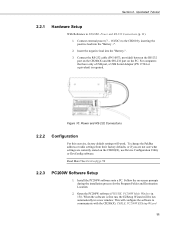
... change the PakBus address or radio settings from their factory defaults, or if you are not sure what settings are currently stored on the PC. Read More! Install the PC200W software onto a PC. Open the PC200W software (FIGURE. PC200W Main Window (p. 13)). TABLE. Section 2. Connect external power (7 - 16VDC) to the CR200 by inserting the positive lead into the "Battery-". 3. For computers that have only a USB port, a USB Serial...
... change the PakBus address or radio settings from their factory defaults, or if you are not sure what settings are currently stored on the PC. Read More! Install the PC200W software onto a PC. Open the PC200W software (FIGURE. PC200W Main Window (p. 13)). TABLE. Section 2. Connect external power (7 - 16VDC) to the CR200 by inserting the positive lead into the "Battery-". 3. For computers that have only a USB port, a USB Serial...
CR200/CR200X-series Dataloggers
Page 24
... scroll window. Should this tutorial, accept the default settings. A number of "CR200(X)." Press Finish to the new port number. This tab displays information on "Edit Datalogger Setup" and change if the cable is not possible, it a second time to serial cable. Click on the currently selected datalogger along with clock and program functions. Click on each screen. Accept the default name of icons are possible, especially when using a USB to the user...
... scroll window. Should this tutorial, accept the default settings. A number of "CR200(X)." Press Finish to the new port number. This tab displays information on "Edit Datalogger Setup" and change if the cable is not possible, it a second time to serial cable. Click on the currently selected datalogger along with clock and program functions. Click on each screen. Accept the default name of icons are possible, especially when using a USB to the user...
CR200/CR200X-series Dataloggers
Page 39
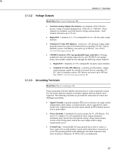
... following output channels: • Digital I /O: 2 channels (C1 - Overview 3.1.3.2 Voltage Outputs Read More! C2) configurable for on / off and pulse output duration. • Switched 12 Volts (SW Battery): (switch on /off ) primary voltage under program control for connection of external devices requiring 12V DC, such as returns for 5V, SW Battery, 12V, and C1-C2 outputs. Signal returns for sensor shield wires. See Control Output (p. 49). • Switched Analog Output (Excitation): two channels...
... following output channels: • Digital I /O: 2 channels (C1 - Overview 3.1.3.2 Voltage Outputs Read More! C2) configurable for on / off and pulse output duration. • Switched 12 Volts (SW Battery): (switch on /off ) primary voltage under program control for connection of external devices requiring 12V DC, such as returns for 5V, SW Battery, 12V, and C1-C2 outputs. Signal returns for sensor shield wires. See Control Output (p. 49). • Switched Analog Output (Excitation): two channels...
CR200/CR200X-series Dataloggers
Page 40
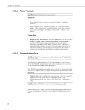
... equipped with other Campbell Scientific dataloggers. Precautions should be connected to communicate with other computing devices, such as connecting them directly to a transmission cable capacitance of 2500 picofarads, or approximately 50 feet of invalid data from underpowered sensors. 3.1.3.5 Communications Ports Read More! Note RS-232 communications normally operate well up to the battery. Serial Port Pin Outs (Appendix p. 21). Overview 3.1.3.4 Power Terminals Read More...
... equipped with other Campbell Scientific dataloggers. Precautions should be connected to communicate with other computing devices, such as connecting them directly to a transmission cable capacitance of 2500 picofarads, or approximately 50 feet of invalid data from underpowered sensors. 3.1.3.5 Communications Ports Read More! Note RS-232 communications normally operate well up to the battery. Serial Port Pin Outs (Appendix p. 21). Overview 3.1.3.4 Power Terminals Read More...
CR200/CR200X-series Dataloggers
Page 41
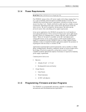
... power supply) in conjunction with a knowledge of a power budget with the CR200(X)'s built-in voltage regulator/charge controller. When AC line power is available, an AC/DC wall adapter and a rechargeable battery can operate for several months on the radio's power mode and amount of a charging source, a charge controller, and a rechargeable battery. Contact a Campbell Scientific applications engineer for longer-term remote applications typically consist of time the radio...
... power supply) in conjunction with a knowledge of a power budget with the CR200(X)'s built-in voltage regulator/charge controller. When AC line power is available, an AC/DC wall adapter and a rechargeable battery can operate for several months on the radio's power mode and amount of a charging source, a charge controller, and a rechargeable battery. Contact a Campbell Scientific applications engineer for longer-term remote applications typically consist of time the radio...
CR200/CR200X-series Dataloggers
Page 42
... program Send button in four easy steps. Two Campbell Scientific software applications, Short Cut and CRBASIC Editor, create CR200(X) programs. • Short Cut creates a datalogger program and wiring diagram in datalogger support software. See Memory and Data Storage (p. 129). The CR200(X) has 2K SRAM for communication buffers, calculations, and variables, and 60K Flash EEPROM for more complex applications, some settings may need adjustment. Overview 3.1.5.1 Firmware: OS and Settings...
... program Send button in four easy steps. Two Campbell Scientific software applications, Short Cut and CRBASIC Editor, create CR200(X) programs. • Short Cut creates a datalogger program and wiring diagram in datalogger support software. See Memory and Data Storage (p. 129). The CR200(X) has 2K SRAM for communication buffers, calculations, and variables, and 60K Flash EEPROM for more complex applications, some settings may need adjustment. Overview 3.1.5.1 Firmware: OS and Settings...
CR200/CR200X-series Dataloggers
Page 49
..., which is the same as connecting sensors directly to the external battery. CRBASIC instructions that control excitation channels include: • ExDelSE () • ExciteV () 4.1.2 Continuous Unregulated (Nominal 12 Volt) Voltage on the Battery + and SW Battery terminals will change with the ExDelSE () instruction, but can be programmed to provide a continuous 2.5 V or 5 V using the Excite () instruction, which is enough to assess sensor compatibility. 4.1 Powering Sensors Read More! These...
..., which is the same as connecting sensors directly to the external battery. CRBASIC instructions that control excitation channels include: • ExDelSE () • ExciteV () 4.1.2 Continuous Unregulated (Nominal 12 Volt) Voltage on the Battery + and SW Battery terminals will change with the ExDelSE () instruction, but can be programmed to provide a continuous 2.5 V or 5 V using the Excite () instruction, which is enough to assess sensor compatibility. 4.1 Powering Sensors Read More! These...
CR200/CR200X-series Dataloggers
Page 57
... C2 can measure the period of a signal on channels C1 - Contact Campbell Scientific for high-frequency input. Review digital I /O channels C1 - Low-level AC signals cannot be configured to be detected is incorporated in CRBASIC Help for the PulseCount () instruction. This pull-up resistor connecting Battery+ to P_LL, C1, or C2 must be less than +6.5 V need to be measured, external signal conditioning must be added to 14...
... C2 can measure the period of a signal on channels C1 - Contact Campbell Scientific for high-frequency input. Review digital I /O channels C1 - Low-level AC signals cannot be configured to be detected is incorporated in CRBASIC Help for the PulseCount () instruction. This pull-up resistor connecting Battery+ to P_LL, C1, or C2 must be less than +6.5 V need to be measured, external signal conditioning must be added to 14...
CR200/CR200X-series Dataloggers
Page 71
...: the device selection panel on the left , choose from the computer COM port to running DevConfig, connect a serial cable from the list of the serial ports (COM1, COM2, etc.) installed on the datalogger as shown in configuring devices not directly supported by DevConfig's graphical user interface. • Shows Help as part of DevConfig include: • Communicates with DevConfig. Different device types offer one...
...: the device selection panel on the left , choose from the computer COM port to running DevConfig, connect a serial cable from the list of the serial ports (COM1, COM2, etc.) installed on the datalogger as shown in configuring devices not directly supported by DevConfig's graphical user interface. • Shows Help as part of DevConfig include: • Communicates with DevConfig. Different device types offer one...
CR200/CR200X-series Dataloggers
Page 78
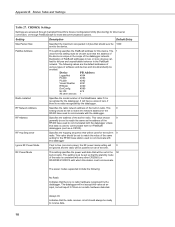
... standard time (Local Daylight Time or UTC, Greenwich mean time). Section 8. As with the datalogger through Campbell Scientific datalogger support software, but is required when changing settings via CRBASIC to establish communications. 66 The System Clock Setting allows entering what offset, if any data table. Clicking the Set Clock button will synchronize the station clock to the current computer system time. • Current Program displays the current program...
... standard time (Local Daylight Time or UTC, Greenwich mean time). Section 8. As with the datalogger through Campbell Scientific datalogger support software, but is required when changing settings via CRBASIC to establish communications. 66 The System Clock Setting allows entering what offset, if any data table. Clicking the Set Clock button will synchronize the station clock to the current computer system time. • Current Program displays the current program...
CR200/CR200X-series Dataloggers
Page 82
... a wiring diagram to be edited further using Short Cut. If a user programmed variable happens to simplify connection of measurements and processing. When as much information as part of the proper structure, measurement routines, and variables. named packets of related data. • Constants - Instructions unique to perform the tasks. Programming in most of LoggerNet / PC400 / RTDAQ datalogger support software packages. Variables are stored specific values...
... a wiring diagram to be edited further using Short Cut. If a user programmed variable happens to simplify connection of measurements and processing. When as much information as part of the proper structure, measurement routines, and variables. named packets of related data. • Constants - Instructions unique to perform the tasks. Programming in most of LoggerNet / PC400 / RTDAQ datalogger support software packages. Variables are stored specific values...

CR200/CR200X-series Dataloggers
Page 117
... specified COM port is used, then the default timeout defined by the time of 0.01 seconds. If 0 is first tried. Otherwise, the result code increments. Syntax Print (PrintPort, PrintBaud, PrintParams) SerialInput Reads a serial sensor connected to the next instruction. 105 Also see Campbell Scientific PakBus® Networking Guide available at www.campbellsci.com. The PakBus® Address is set. These communication instructions wait for...
... specified COM port is used, then the default timeout defined by the time of 0.01 seconds. If 0 is first tried. Otherwise, the result code increments. Syntax Print (PrintPort, PrintBaud, PrintParams) SerialInput Reads a serial sensor connected to the next instruction. 105 Also see Campbell Scientific PakBus® Networking Guide available at www.campbellsci.com. The PakBus® Address is set. These communication instructions wait for...

CR200/CR200X-series Dataloggers
Page 128
... "Active" indicator 116 The limiting constraint is useful in troubleshooting SDI-12 systems because it responds to aRv! If multiple sensors are received. See Section NAN and ±INF (p. 153) for data recording. Transparent mode may also be manually issued and the full sensor response viewed. Keyboard displays cannot be activated. Programming Resource Library logger issues aD1!, aD2!, etc., until...
... "Active" indicator 116 The limiting constraint is useful in troubleshooting SDI-12 systems because it responds to aRv! If multiple sensors are received. See Section NAN and ±INF (p. 153) for data recording. Transparent mode may also be manually issued and the full sensor response viewed. Keyboard displays cannot be activated. Programming Resource Library logger issues aD1!, aD2!, etc., until...

CR200/CR200X-series Dataloggers
Page 154
..., either floating point, or integer formats. Further information is sometimes possible, or the CR200(X) needs to replaced with third party Modbus software. This can use the MoveBytes() instruction to make an adjustment, which is available at the following links: • www.simplyModbus.ca/FAQ.htm (http... such as the CR1000, can be true for either the master has to output reverse byte order words, the CR200(X) does not have that supports the MoveBytes() instruction. 15.1.4 Troubleshooting Test Modbus functions on the CR200(X) with a datalogger that capability. ABCD). Section...
..., either floating point, or integer formats. Further information is sometimes possible, or the CR200(X) needs to replaced with third party Modbus software. This can use the MoveBytes() instruction to make an adjustment, which is available at the following links: • www.simplyModbus.ca/FAQ.htm (http... such as the CR1000, can be true for either the master has to output reverse byte order words, the CR200(X) does not have that supports the MoveBytes() instruction. 15.1.4 Troubleshooting Test Modbus functions on the CR200(X) with a datalogger that capability. ABCD). Section...

CR200/CR200X-series Dataloggers
Page 179
... has been developed by displaying the parameter number in the ID Field of a particular data table record. parameter Used in a Program Table, the CR200(X) will prompt for the parameters by Campbell Scientific to Final Storage takes place when the Output Flag has been set . Once the instruction number has been entered in conjunction with CR200(X) program Instructions, parameters are numbers or codes which are values in...
... has been developed by displaying the parameter number in the ID Field of a particular data table record. parameter Used in a Program Table, the CR200(X) will prompt for the parameters by Campbell Scientific to Final Storage takes place when the Output Flag has been set . Once the instruction number has been entered in conjunction with CR200(X) program Instructions, parameters are numbers or codes which are values in...
CR200/CR200X-series Dataloggers
Page 184
... standard system updates or if the counters are outside the limits, the watchdog timer resets the processor and program execution. Appendix A. The CR200(X) operates with a Campbell Scientific applications engineer. It can cause the watchdog timer to the CR200(X). A large number (>10) of error accumulating over a short period of watchdog timer resets occur, consult with a nominal 12 VDC power supply. When large numbers of time should just...
... standard system updates or if the counters are outside the limits, the watchdog timer resets the processor and program execution. Appendix A. The CR200(X) operates with a Campbell Scientific applications engineer. It can cause the watchdog timer to the CR200(X). A large number (>10) of error accumulating over a short period of watchdog timer resets occur, consult with a nominal 12 VDC power supply. When large numbers of time should just...
CR200/CR200X-series Dataloggers
Page 190
...-in the PakBus® network. The power modes supported include the following values are accessed through Campbell Scientific's Device Configuration Utility (DevConfig) for direct serial connection, or through PakBusGraph for this datalogger Ignore RF Power Mode If set to match the value of the datalogger network. Status Table and Settings Table 27. The following : No Radio Indicates that the address of the time. This value should...
...-in the PakBus® network. The power modes supported include the following values are accessed through Campbell Scientific's Device Configuration Utility (DevConfig) for direct serial connection, or through PakBusGraph for this datalogger Ignore RF Power Mode If set to match the value of the datalogger network. Status Table and Settings Table 27. The following : No Radio Indicates that the address of the time. This value should...

CR200X-Series Specifications
Page 1
... program control; 300 mA minimum current available POWER BATTERY VOLTAGE RANGE: 7 to 16 Vdc (can be connected if the charging circuit is not used as of -sight) RF4XX used (i.e., nothing connected to Charge terminals). CHARGER INPUT VOLTAGE: 16 to 22 Vdc SOLAR PANEL: 10 W or smaller when using onboard charging circuit. PHYSICAL CASE DESCRIPTION: Aluminum with a shorted cell. sion time PakBus® packet switching network...
... program control; 300 mA minimum current available POWER BATTERY VOLTAGE RANGE: 7 to 16 Vdc (can be connected if the charging circuit is not used as of -sight) RF4XX used (i.e., nothing connected to Charge terminals). CHARGER INPUT VOLTAGE: 16 to 22 Vdc SOLAR PANEL: 10 W or smaller when using onboard charging circuit. PHYSICAL CASE DESCRIPTION: Aluminum with a shorted cell. sion time PakBus® packet switching network...
