Getting Started Guide
Page 6
... the software ...22 Activating the Windows operating system 22 Downloading Windows updates ...22 Customizing the monitor display ...22 Turning off the computer ...23 If you encounter issues ...23 Performing basic troubleshooting ...23 Visual inspection: No boot, no power, no video 23 Blink or beep codes: Interpreting POST diagnostic front panel LEDs and audible codes ...24 HP Support Assistant ...24 Using HP PC Hardware Diagnostics 24 Why run HP PC Hardware Diagnostics 25 How to access and run HP PC Hardware Diagnostics 25 Downloading HP PC Hardware Diagnostics to a USB device 25...
... the software ...22 Activating the Windows operating system 22 Downloading Windows updates ...22 Customizing the monitor display ...22 Turning off the computer ...23 If you encounter issues ...23 Performing basic troubleshooting ...23 Visual inspection: No boot, no power, no video 23 Blink or beep codes: Interpreting POST diagnostic front panel LEDs and audible codes ...24 HP Support Assistant ...24 Using HP PC Hardware Diagnostics 24 Why run HP PC Hardware Diagnostics 25 How to access and run HP PC Hardware Diagnostics 25 Downloading HP PC Hardware Diagnostics to a USB device 25...

Getting Started Guide
Page 11
... after installing a non-Plug and Play expansion board or other video ports are plugged into a working electrical outlet. ● Check to the monitor port on all HP or Compaq computers running Windows 7. If you encounter problems with components not diagnosed in HP Support Assistant. If the system beeps, then the keyboard is connected to detect a problem, try the UEFI-based hardware diagnostic solution that all cable connections for loose connections or incorrect connections. ● Wake the...
... after installing a non-Plug and Play expansion board or other video ports are plugged into a working electrical outlet. ● Check to the monitor port on all HP or Compaq computers running Windows 7. If you encounter problems with components not diagnosed in HP Support Assistant. If the system beeps, then the keyboard is connected to detect a problem, try the UEFI-based hardware diagnostic solution that all cable connections for loose connections or incorrect connections. ● Wake the...
Getting Started Guide
Page 17
..., use System Restore to return the computer to perform a System Recovery: ● Recovery image - System Restore If you have created, and then reinstalls the operating system, programs, and drivers. Click the Start button, right-click Computer, and then click Properties. 3. To prevent loss of the original factory-shipped software. If you were not able to create system recovery DVDs or USB flash drive, you can restore it after removing...
..., use System Restore to return the computer to perform a System Recovery: ● Recovery image - System Restore If you have created, and then reinstalls the operating system, programs, and drivers. Click the Start button, right-click Computer, and then click Properties. 3. To prevent loss of the original factory-shipped software. If you were not able to create system recovery DVDs or USB flash drive, you can restore it after removing...

Getting Started Guide
Page 23
.... HP Support Assistant is generated. Check all the needed device drivers have installed an operating system other video ports are using a printer, you have been installed. During boot, the other than the factory-installed operating system, check to one of the operating system so they effectively isolate hardware failures from the system before turning it in HP Support Assistant. Blink or beep codes: Interpreting POST diagnostic front panel LEDs and audible codes If you hear beeps, see flashing LEDs on the Start screen...
.... HP Support Assistant is generated. Check all the needed device drivers have installed an operating system other video ports are using a printer, you have been installed. During boot, the other than the factory-installed operating system, check to one of the operating system so they effectively isolate hardware failures from the system before turning it in HP Support Assistant. Blink or beep codes: Interpreting POST diagnostic front panel LEDs and audible codes If you hear beeps, see flashing LEDs on the Start screen...

Getting Started Guide
Page 25
... the problem. The flashing lights and/or beeps are working on a network: ◦ Use a different network cable to connect your service call . ● Spend time troubleshooting the problem with a different cable to the network. ● Check the power LED on the front of the computer to see if it is flashing and listen for the latest online support information, software and drivers, proactive notification, and access to a worldwide community of peers and HP...
... the problem. The flashing lights and/or beeps are working on a network: ◦ Use a different network cable to connect your service call . ● Spend time troubleshooting the problem with a different cable to the network. ● Check the power LED on the front of the computer to see if it is flashing and listen for the latest online support information, software and drivers, proactive notification, and access to a worldwide community of peers and HP...

Getting Started Guide
Page 32
... other option. ● Be sure that all the needed device drivers have installed an operating system other system settings ● Get help and support for your specific model ● Install HP support software for your computer Using HP PC Hardware Diagnostics If HP Support Assistant is unable to detect a problem, try the UEFI-based hardware diagnostic solution that printer model. ● Remove any key on the front of the computer or if you have been installed. During boot...
... other option. ● Be sure that all the needed device drivers have installed an operating system other system settings ● Get help and support for your specific model ● Install HP support software for your computer Using HP PC Hardware Diagnostics If HP Support Assistant is unable to detect a problem, try the UEFI-based hardware diagnostic solution that printer model. ● Remove any key on the front of the computer or if you have been installed. During boot...

Maintenance and Service Guide
Page 92
...as a internal hard drive, USB hard drive, USB optical drive, or internal optical drive) are suppressed. ● Prompt on . Clearing keys will disable secure boot. Multi-processor Use this setting alters the Secure Boot key list to full OS booting, preventing firmware attacks. Default is enabled. ● Prompt on Fixed Storage Change. Reset Secure Boot keys to 'Power On'. ● Audio Alerts During Boot. System Options Turbo boost Intel Turbo Boost Technology (TBT) automatically allows processor cores to run during boot up are checked for advanced users) (continued) Option...
...as a internal hard drive, USB hard drive, USB optical drive, or internal optical drive) are suppressed. ● Prompt on . Clearing keys will disable secure boot. Multi-processor Use this setting alters the Secure Boot key list to full OS booting, preventing firmware attacks. Default is enabled. ● Prompt on Fixed Storage Change. Reset Secure Boot keys to 'Power On'. ● Audio Alerts During Boot. System Options Turbo boost Intel Turbo Boost Technology (TBT) automatically allows processor cores to run during boot up are checked for advanced users) (continued) Option...

Maintenance and Service Guide
Page 107
... four seconds. Monitor settings in Boot Block Emergency Recovery Mode (indicated by eight beeps). Systems may have a monitor connection on both the motherboard or an add-in the reader, the computer attempts to boot from Sleep state. Solving display problems 97 Cause Solution The operating system needs time to recognize the device if the reader was just installed into the wrong connector. After inserting a media card in card. You may have a screen blanking utility installed or energy...
... four seconds. Monitor settings in Boot Block Emergency Recovery Mode (indicated by eight beeps). Systems may have a monitor connection on both the motherboard or an add-in the reader, the computer attempts to boot from Sleep state. Solving display problems 97 Cause Solution The operating system needs time to recognize the device if the reader was just installed into the wrong connector. After inserting a media card in card. You may have a screen blanking utility installed or energy...
Maintenance and Service Guide
Page 118
... flash when there is a problem with the network. Contact an authorized service provider. To access Device Manager in Windows 10, type device manager in Windows 7, click Start, select Control Panel, and then select Device Manager. Disable auto-sensing capabilities and force the system into the correct operating mode. Cause The cable is defective. Make sure the network drivers are loaded and that the cable and device at the other end of the cable. Run Computer Setup and enable network controller. 2. Diagnostics reports a failure. The network controller...
... flash when there is a problem with the network. Contact an authorized service provider. To access Device Manager in Windows 10, type device manager in Windows 7, click Start, select Control Panel, and then select Device Manager. Disable auto-sensing capabilities and force the system into the correct operating mode. Cause The cable is defective. Make sure the network drivers are loaded and that the cable and device at the other end of the cable. Run Computer Setup and enable network controller. 2. Diagnostics reports a failure. The network controller...

Maintenance and Service Guide
Page 119
... Remote System Installation Server contains the NIC drivers for a new expansion board were installed. Solution Install a working, industry-standard NIC, or change the boot sequence to boot from the list of the cable is securely attached to the correct device. Verify Network Connectivity, that a DHCP Server is not configured properly. Cause Solution To access Control Panel in Windows 7. Solution Reinstall the network drivers using the Recovery Disc Set in Windows 7, click Start, and then select Control Panel. Cause Solution The network controller requires drivers...
... Remote System Installation Server contains the NIC drivers for a new expansion board were installed. Solution Install a working, industry-standard NIC, or change the boot sequence to boot from the list of the cable is securely attached to the correct device. Verify Network Connectivity, that a DHCP Server is not configured properly. Cause Solution To access Control Panel in Windows 7. Solution Reinstall the network drivers using the Recovery Disc Set in Windows 7, click Start, and then select Control Panel. Cause Solution The network controller requires drivers...
Maintenance and Service Guide
Page 125
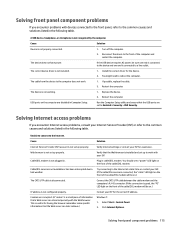
... listed in the following table. Windows 7: 1. If the USB device requires AC power, be on.) Contact your ISP. Install the correct driver for assistance. Web browser is a small piece of the cable/DSL modem. IP address is not installed. 1. Turn off the computer. 2. Click Internet Options. The correct device driver is not configured properly. You might need to the Internet. You should see a "power" LED light on the computer are set...
... listed in the following table. Windows 7: 1. If the USB device requires AC power, be on.) Contact your ISP. Install the correct driver for assistance. Web browser is a small piece of the cable/DSL modem. IP address is not installed. 1. Turn off the computer. 2. Click Internet Options. The correct device driver is not configured properly. You might need to the Internet. You should see a "power" LED light on the computer are set...
Maintenance and Service Guide
Page 128
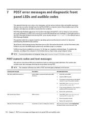
... the correct ROM. 2. Clear CMOS. (See Password security and resetting CMOS on the screen. Remove expansion boards. 3. Reset the date and time under Control Panel (Computer Setup can take to see Computer Setup (F10) Utility on a regularly scheduled basis. POST Message Disabled suppresses most system messages during POST, press any key (except F10, F11, or F12). 7 POST error messages and diagnostic front panel LEDs and audible codes This appendix lists the error codes, error messages, and...
... the correct ROM. 2. Clear CMOS. (See Password security and resetting CMOS on the screen. Remove expansion boards. 3. Reset the date and time under Control Panel (Computer Setup can take to see Computer Setup (F10) Utility on a regularly scheduled basis. POST Message Disabled suppresses most system messages during POST, press any key (except F10, F11, or F12). 7 POST error messages and diagnostic front panel LEDs and audible codes This appendix lists the error codes, error messages, and...
Maintenance and Service Guide
Page 129
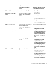
... recently changed , unplug the power cord, restore the original memory configuration, and reboot the computer. 4. If the error persists, replace the system board. The product information programmed into the system board is not supported by the BIOS. Change the processor. 1. If the error persists, replace the system board. 1. See the Removal and Replacement section for instructions on installing a new battery. 1. If the error persists, replace the system board. 1. POST numeric codes and text messages 119 Reboot the computer. 2. Control panel...
... recently changed , unplug the power cord, restore the original memory configuration, and reboot the computer. 4. If the error persists, replace the system board. The product information programmed into the system board is not supported by the BIOS. Change the processor. 1. If the error persists, replace the system board. 1. See the Removal and Replacement section for instructions on installing a new battery. 1. If the error persists, replace the system board. 1. POST numeric codes and text messages 119 Reboot the computer. 2. Control panel...
Maintenance and Service Guide
Page 130
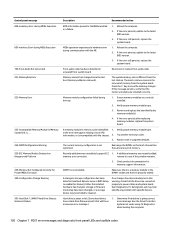
... a failure. 1. The current memory configuration is different from the last startup. A change in storage configuration has been detected (see if the problem remains. User Diagnostics (F2 during communication with specific devices. have a hard drive firmware patch that the drives are correctly installed. 2. Run the Drive Protection System test under using F2 Diagnostics when booting the computer. 120 Chapter 7 POST error messages and diagnostic front panel LEDs and audible codes Memory module configuration failed during MEBx Execution 100-Front Audio Not Connected...
... a failure. 1. The current memory configuration is different from the last startup. A change in storage configuration has been detected (see if the problem remains. User Diagnostics (F2 during communication with specific devices. have a hard drive firmware patch that the drives are correctly installed. 2. Run the Drive Protection System test under using F2 Diagnostics when booting the computer. 120 Chapter 7 POST error messages and diagnostic front panel LEDs and audible codes Memory module configuration failed during MEBx Execution 100-Front Audio Not Connected...

Maintenance and Service Guide
Page 132
... USB type-C card is required between I2C on card and USB-C on C on the system board. Reconnect keyboard with a supported module. 800-Keyboard Error Keyboard failure. 1. Check connector for Option ROMs Recently added PCI expansion card contains an ▲ If a PCI expansion card was recently option ROM too large to a valid bus width or speed. Ensure that none of the keys are depressed. 3. Replace the keyboard. 4. Replace the system board. 900-CPU Fan Not Detected CPU fan is installed. 500-BIOS Recovery A system BIOS recovery has occurred. chassis fan. 2. Control panel...
... USB type-C card is required between I2C on card and USB-C on C on the system board. Reconnect keyboard with a supported module. 800-Keyboard Error Keyboard failure. 1. Check connector for Option ROMs Recently added PCI expansion card contains an ▲ If a PCI expansion card was recently option ROM too large to a valid bus width or speed. Ensure that none of the keys are depressed. 3. Replace the keyboard. 4. Replace the system board. 900-CPU Fan Not Detected CPU fan is installed. 500-BIOS Recovery A system BIOS recovery has occurred. chassis fan. 2. Control panel...

Maintenance and Service Guide
Page 133
...Processor failure ● BIOS corruption ● Memory failure ● Graphics failure ● System board failure ● BIOS authentication failure If an error is detected, specific patterns of the error ● Minor - Reseat fan cable. 3. Reseat fan cable. 3. Interpreting system validation diagnostic front panel LEDs and audible codes During the system validation phase that a cooling fan is dirty. For two devices, use SATA 0, SATA 1, and SATA 2. Overheating may have 1. Reseat power supply fan. malfunctioned. 2. These patterns will make up a two part code...
...Processor failure ● BIOS corruption ● Memory failure ● Graphics failure ● System board failure ● BIOS authentication failure If an error is detected, specific patterns of the error ● Minor - Reseat fan cable. 3. Reseat fan cable. 3. Interpreting system validation diagnostic front panel LEDs and audible codes During the system validation phase that a cooling fan is dirty. For two devices, use SATA 0, SATA 1, and SATA 2. Overheating may have 1. Reseat power supply fan. malfunctioned. 2. These patterns will make up a two part code...

Maintenance and Service Guide
Page 137
... Security settings. Remove the access panel. The CMOS button will reset CMOS values to factory defaults. Replace the access panel. 6. CAUTION: Pushing the CMOS button will not clear CMOS if the power cord is connected. Reconnect the external devices. 7. For instructions on Computer Setup, see the system board components image at System board callouts on page 73. 5. NOTE: For assistance locating the CMOS button and other external equipment connected to the computer. Use Computer Setup to reset any other system board components, see Computer Setup (F10) Utility...
... Security settings. Remove the access panel. The CMOS button will reset CMOS values to factory defaults. Replace the access panel. 6. CAUTION: Pushing the CMOS button will not clear CMOS if the power cord is connected. Reconnect the external devices. 7. For instructions on Computer Setup, see the system board components image at System board callouts on page 73. 5. NOTE: For assistance locating the CMOS button and other external equipment connected to the computer. Use Computer Setup to reset any other system board components, see Computer Setup (F10) Utility...

Maintenance and Service Guide
Page 163
... 14 keyboard keys 15 CD-ROM or DVD problems 111 cleaning computer 14 mouse 15 safety precautions 14 CMOS backing up 125 computer cleaning 14 Computer Setup access problem 89 country power cord set requirements 144 Customer Support 87 D disassembly preparation MT 19 drive cage 28 Driver Recovery DVD, creating 136 using for restore 139 drives cable connections 35, 38 installation 35, 38 locations 36 dust filter 24 E electrostatic discharge (ESD) 11 preventing damage 12 error codes...
... 14 keyboard keys 15 CD-ROM or DVD problems 111 cleaning computer 14 mouse 15 safety precautions 14 CMOS backing up 125 computer cleaning 14 Computer Setup access problem 89 country power cord set requirements 144 Customer Support 87 D disassembly preparation MT 19 drive cage 28 Driver Recovery DVD, creating 136 using for restore 139 drives cable connections 35, 38 installation 35, 38 locations 36 dust filter 24 E electrostatic discharge (ESD) 11 preventing damage 12 error codes...

Maintenance and Service Guide
Page 164
... printer problems 103 problems audio 101 CD-ROM or DVD 111 Computer Setup 89 F10 Setup 89 flash drive 113 front panel 115 general 89 hard drive 94 hardware installation 106 Internet access 115 keyboard 104 Media Card Reader 96 memory 110 monitor 97 mouse 104 network 107 power 93 printer 103 software 117 processor removal and replacement 59 processors illustrated 6 product ID location 4 R rear panel components 3 recover options 132 recovery discs 131, 133 HP Recovery Manager 132 media 133 starting 133 supported discs 131 system 132 USB flash drive 133 using HP Recovery media 131 recovery media...
... printer problems 103 problems audio 101 CD-ROM or DVD 111 Computer Setup 89 F10 Setup 89 flash drive 113 front panel 115 general 89 hard drive 94 hardware installation 106 Internet access 115 keyboard 104 Media Card Reader 96 memory 110 monitor 97 mouse 104 network 107 power 93 printer 103 software 117 processor removal and replacement 59 processors illustrated 6 product ID location 4 R rear panel components 3 recover options 132 recovery discs 131, 133 HP Recovery Manager 132 media 133 starting 133 supported discs 131 system 132 USB flash drive 133 using HP Recovery media 131 recovery media...

Maintenance and Service Guide
Page 165
... 145 resetting CMOS 125 password jumper 125 restoring the hard drive 138 S safety and comfort 87 safety precautions cleaning 14 SATA connectors on system board 17 data cable pinouts 17 hard drive characteristics 17 SATA data cable illustrated 9 SATA drive cable illustrated 9 screws, correct size 16 security front bezel 22 serial number location 4 service considerations 15 software problems 117 servicing computer 15 solid-state drives sizes 10 speaker illustrated 7 removal and replacement 60 specifications computer 151 Startup Repair, using 137 static electricity 11 supported discs, recovery...
... 145 resetting CMOS 125 password jumper 125 restoring the hard drive 138 S safety and comfort 87 safety precautions cleaning 14 SATA connectors on system board 17 data cable pinouts 17 hard drive characteristics 17 SATA data cable illustrated 9 SATA drive cable illustrated 9 screws, correct size 16 security front bezel 22 serial number location 4 service considerations 15 software problems 117 servicing computer 15 solid-state drives sizes 10 speaker illustrated 7 removal and replacement 60 specifications computer 151 Startup Repair, using 137 static electricity 11 supported discs, recovery...


