

User Manual
Page 8
... can only be gained by service persons or by overload. ● Make sure the plug is properly connected to the power socket. Power Supply ● The input voltage should not be touched without taking care. For device with this sticker, this equipment must be securely attached to the floor/wall in accordance with the installation instructions. ● Never place the...
... can only be gained by service persons or by overload. ● Make sure the plug is properly connected to the power socket. Power Supply ● The input voltage should not be touched without taking care. For device with this sticker, this equipment must be securely attached to the floor/wall in accordance with the installation instructions. ● Never place the...

User Manual
Page 9
... product does not work properly, please contact your dealer for password and security configuration. Network Camera User Manual White Light Illuminator (If supported) ● Possibly hazardous optical radiation emitted from the device, immediately turn on the white light when you assemble, install or maintain the camera. Transportation ● Keep the device in original or similar packaging while transporting it to 140 °F), and the operating humidity shall...
... product does not work properly, please contact your dealer for password and security configuration. Network Camera User Manual White Light Illuminator (If supported) ● Possibly hazardous optical radiation emitted from the device, immediately turn on the white light when you assemble, install or maintain the camera. Transportation ● Keep the device in original or similar packaging while transporting it to 140 °F), and the operating humidity shall...

User Manual
Page 11
Network Camera User Manual Contents Chapter 1 System Requirement 1 Chapter 2 Device Activation and Accessing 2 2.1 Activate the Device via SADP 2 2.2 Activate the Device via Browser 2 2.3 Login ...3 2.3.1 Plug-in Installation ...3 2.3.2 Admin Password Recovery 4 2.3.3 Illegal Login Lock ...5 Chapter 3 Live View ...6 3.1 Live View Parameters ...6 3.1.1 Enable and Disable Live View 6 3.1.2 Adjust Aspect Ratio ...6 3.1.3 Live View Stream Type 6 3.1.4 Select the Third-Party Plug-in 6 3.1.5 Window Division ...7 3.1.6 Light ...7 3.1.7 Count Pixel ...7 3.1.8 Start Digital Zoom ...7 3.1.9 ...
Network Camera User Manual Contents Chapter 1 System Requirement 1 Chapter 2 Device Activation and Accessing 2 2.1 Activate the Device via SADP 2 2.2 Activate the Device via Browser 2 2.3 Login ...3 2.3.1 Plug-in Installation ...3 2.3.2 Admin Password Recovery 4 2.3.3 Illegal Login Lock ...5 Chapter 3 Live View ...6 3.1 Live View Parameters ...6 3.1.1 Enable and Disable Live View 6 3.1.2 Adjust Aspect Ratio ...6 3.1.3 Live View Stream Type 6 3.1.4 Select the Third-Party Plug-in 6 3.1.5 Window Division ...7 3.1.6 Light ...7 3.1.7 Count Pixel ...7 3.1.8 Start Digital Zoom ...7 3.1.9 ...
User Manual
Page 13
Network Camera User Manual 5.1.3 Set NAS ...28 5.1.4 eMMC Protection ...28 5.1.5 Set Cloud Storage ...29 5.2 Video Recording ...29 5.2.1 Record Automatically 29 5.2.2 Record Manually ...31 5.2.3 Playback and Download Video 31 5.3 Capture Configuration ...32 5.3.1 Capture Automatically 32 5.3.2 Capture Manually ...32 5.3.3 View and Download Picture 32 Chapter 6 Event and Alarm ...34 6.1 Basic Event ...34 6.1.1 Set Motion Detection 34 6.1.2 Set Video Tampering Alarm 36 6.1.3 Set Exception Alarm ...37 6.1.4 Set Alarm Input ...38 6.1.5 Set Video Quality Diagnosis 38 6.1.6 Set Vibration ...
Network Camera User Manual 5.1.3 Set NAS ...28 5.1.4 eMMC Protection ...28 5.1.5 Set Cloud Storage ...29 5.2 Video Recording ...29 5.2.1 Record Automatically 29 5.2.2 Record Manually ...31 5.2.3 Playback and Download Video 31 5.3 Capture Configuration ...32 5.3.1 Capture Automatically 32 5.3.2 Capture Manually ...32 5.3.3 View and Download Picture 32 Chapter 6 Event and Alarm ...34 6.1 Basic Event ...34 6.1.1 Set Motion Detection 34 6.1.2 Set Video Tampering Alarm 36 6.1.3 Set Exception Alarm ...37 6.1.4 Set Alarm Input ...38 6.1.5 Set Video Quality Diagnosis 38 6.1.6 Set Vibration ...

User Manual
Page 14
... Dial Up Connection 53 7.8 Set Network Service ...54 7.9 Set Open Network Video Interface 55 7.10 Set ISUP ...55 7.11 Set Alarm Server ...56 7.12 Access Camera via Hik-Connect 56 7.12.1 Enable Hik-Connect Service on Camera 57 7.12.2 Set Up Hik-Connect 58 7.12.3 Add Camera to Hik-Connect 58 Chapter 8 Arming Schedule and Alarm Linkage 60 8.1 Set Arming Schedule ...60 8.2 Linkage Method Settings ...60 8.2.1 Trigger Alarm Output 60 8.2.2 FTP/NAS/Memory Card Uploading 61 8.2.3 Send Email ...62 8.2.4 Notify Surveillance Center...
... Dial Up Connection 53 7.8 Set Network Service ...54 7.9 Set Open Network Video Interface 55 7.10 Set ISUP ...55 7.11 Set Alarm Server ...56 7.12 Access Camera via Hik-Connect 56 7.12.1 Enable Hik-Connect Service on Camera 57 7.12.2 Set Up Hik-Connect 58 7.12.3 Add Camera to Hik-Connect 58 Chapter 8 Arming Schedule and Alarm Linkage 60 8.1 Set Arming Schedule ...60 8.2 Linkage Method Settings ...60 8.2.1 Trigger Alarm Output 60 8.2.2 FTP/NAS/Memory Card Uploading 61 8.2.3 Send Email ...62 8.2.4 Notify Surveillance Center...
User Manual
Page 16
Network Camera User Manual 9.16.4 Set HTTPS ...72 9.16.5 Set QoS ...72 9.16.6 Set IEEE 802.1X ...72 9.16.7 Control Timeout Settings 73 9.16.8 Search Security Audit Logs 73 9.16.9 SSH ...73 9.17 Certificate Management ...74 9.17.1 Create Self-signed Certificate 74 9.17.2 Create Certificate Request 74 9.17.3 Import Certificate ...74 9.17.4 Install Server/Client Certificate 75 9.17.5 Install CA Certificate 75 9.17.6 Enable Certificate...
Network Camera User Manual 9.16.4 Set HTTPS ...72 9.16.5 Set QoS ...72 9.16.6 Set IEEE 802.1X ...72 9.16.7 Control Timeout Settings 73 9.16.8 Search Security Audit Logs 73 9.16.9 SSH ...73 9.17 Certificate Management ...74 9.17.1 Create Self-signed Certificate 74 9.17.2 Create Certificate Request 74 9.17.3 Import Certificate ...74 9.17.4 Install Server/Client Certificate 75 9.17.5 Install CA Certificate 75 9.17.6 Enable Certificate...

User Manual
Page 20
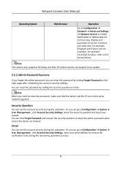
... 52+ Click to ensure normal display and operation. Click OK. 6. For detailed restricted function, refer to the device. 7. Input 192.168.1.64 in installation. Input the activation password to log in installation is 192.168.1.64. Operating System Windows Mac OS Web Browser Operation ● Internet Explorer 8+ Follow pop-up prompts to 192.168.1.100. 3. Network Camera User Manual Note The default IP address of the device is not...
... 52+ Click to ensure normal display and operation. Click OK. 6. For detailed restricted function, refer to the device. 7. Input 192.168.1.64 in installation. Input the activation password to log in installation is 192.168.1.64. Operating System Windows Mac OS Web Browser Operation ● Internet Explorer 8+ Follow pop-up prompts to 192.168.1.100. 3. Network Camera User Manual Note The default IP address of the device is not...
User Manual
Page 21
... support Linux system. 2.3.2 Admin Password Recovery If you forget the admin password, you can reset the password by setting the security question or email. You can set the account security during the recovering operation process. 4 Network Camera User Manual Operating System Web Browser Operation Go to Configuration → Network → Advanced Settings → Network Service to the actual device. Or you can go to Configuration → System → User Management , click Account Security Settings, select the security question and input your email address...
... support Linux system. 2.3.2 Admin Password Recovery If you forget the admin password, you can reset the password by setting the security question or email. You can set the account security during the recovering operation process. 4 Network Camera User Manual Operating System Web Browser Operation Go to Configuration → Network → Advanced Settings → Network Service to the actual device. Or you can go to Configuration → System → User Management , click Account Security Settings, select the security question and input your email address...

User Manual
Page 25
... with motorized lens. Network Camera User Manual For the device that supports ABF, adjust the lens angle, then focus and click ABF button on live view page. For OSD settings, see Lens Parameters Adjustment . - You can set the arming schedule, and the device will correct lens automatically during the configured time periods. 3.1.11 Quick Set Live View It offers a quick setup of PTZ, display settings, OSD, video/audio and VCA resource settings on the device. Steps 1. Auto Lens Initialization Go to Configuration → System...
... with motorized lens. Network Camera User Manual For the device that supports ABF, adjust the lens angle, then focus and click ABF button on live view page. For OSD settings, see Lens Parameters Adjustment . - You can set the arming schedule, and the device will correct lens automatically during the configured time periods. 3.1.11 Quick Set Live View It offers a quick setup of PTZ, display settings, OSD, video/audio and VCA resource settings on the device. Steps 1. Auto Lens Initialization Go to Configuration → System...

User Manual
Page 34
... Audio It is enabled, the noise in the monitoring screen. For device that supports multiple channels, display settings of the camera. 3. Image Adjustment By adjusting the Brightness, Saturation, Hue, Contrast and Sharpness, the image can be filtered to specifications of image parameters predefined for device connection. ● If the device has built-in microphone and speaker, two-way audio function can be best displayed. 17 Network Camera User Manual 4.4.4 Environmental Noise Filter Set...
... Audio It is enabled, the noise in the monitoring screen. For device that supports multiple channels, display settings of the camera. 3. Image Adjustment By adjusting the Brightness, Saturation, Hue, Contrast and Sharpness, the image can be filtered to specifications of image parameters predefined for device connection. ● If the device has built-in microphone and speaker, two-way audio function can be best displayed. 17 Network Camera User Manual 4.4.4 Environmental Noise Filter Set...
User Manual
Page 45
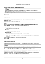
... images, etc. eMMC, short for embedded multimedia card, is only supported by certain device models with an eMMC hardware. Otherwise, using a worn-out eMMC may lead to Configuration → System → Maintenance → System Service for the disk. Go to device boot failure. 28 Network Camera User Manual 4. Enter user name and password of the network disk. Check Enable Automatic Network Replenishment. Click Test to NAS setting...
... images, etc. eMMC, short for embedded multimedia card, is only supported by certain device models with an eMMC hardware. Otherwise, using a worn-out eMMC may lead to Configuration → System → Maintenance → System Service for the disk. Go to device boot failure. 28 Network Camera User Manual 4. Enter user name and password of the network disk. Check Enable Automatic Network Replenishment. Click Test to NAS setting...
User Manual
Page 46
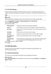
.... 5.2 Video Recording This part introduces the operations of the cloud video manager. It supports IPv4 address. Click Test to Configuration → Storage → Storage Management → Cloud Storage . 2. Go to test the configured settings. 5. Picture Storage The ID of the cloud video manager. The platform requests picture directly from the cloud for details. 29 Network Camera User Manual 5.1.5 Set Cloud Storage It helps to upload the captured pictures and data to use the default port. Server...
.... 5.2 Video Recording This part introduces the operations of the cloud video manager. It supports IPv4 address. Click Test to Configuration → Storage → Storage Management → Cloud Storage . 2. Go to test the configured settings. 5. Picture Storage The ID of the cloud video manager. The platform requests picture directly from the cloud for details. 29 Network Camera User Manual 5.1.5 Set Cloud Storage It helps to upload the captured pictures and data to use the default port. Server...
User Manual
Page 64
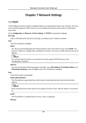
... IPv6 address is connected to should support DHCP (Dynamic Host Configuration Protocol). The device IP address is generated by the server, router, or gateway. Manual You can use SADP to get the device IP address. NIC Type Select a NIC (Network Interface Card) type according to Configuration → Network → Basic Settings → TCP/IP for parameter settings. Route Advertisement The IPv6 address is changed after enabling the function. Input IPv4 Address...
... IPv6 address is connected to should support DHCP (Dynamic Host Configuration Protocol). The device IP address is generated by the server, router, or gateway. Manual You can use SADP to get the device IP address. NIC Type Select a NIC (Network Interface Card) type according to Configuration → Network → Basic Settings → TCP/IP for parameter settings. Route Advertisement The IPv6 address is changed after enabling the function. Input IPv4 Address...

User Manual
Page 67
... for detailed information. Set the IP Address, Subnet Mask and other network parameters of routers. For more information, refer to Forwarding → Virtual Severs , and input the Port Number and IP Address. 4. Note UPnP™ function on Router The following settings are for detailed information. 3. Auto Port Mapping Refer to Set Auto Port Mapping for the device, or you can use the default name. 2. Network Camera User Manual 2. Click Save. Steps...
... for detailed information. Set the IP Address, Subnet Mask and other network parameters of routers. For more information, refer to Forwarding → Virtual Severs , and input the Port Number and IP Address. 4. Note UPnP™ function on Router The following settings are for detailed information. 3. Auto Port Mapping Refer to Set Auto Port Mapping for the device, or you can use the default name. 2. Network Camera User Manual 2. Click Save. Steps...
User Manual
Page 74
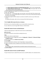
.... 5. Access the camera via Web Browser. Configuration → Network → Advanced Settings → Platform Access 3. Check Enable. 5. Note The verification code is required when you add the camera to your camera before enabling the service. In the app, tap "+" on the cover of the Quick Start Guide of the camera to add the camera. Create a verification code or change the old verification code for a Hik-Connect user account. 3. Enable Hik-Connect Service via SADP Software This part introduce how to enable Hik-Connect service...
.... 5. Access the camera via Web Browser. Configuration → Network → Advanced Settings → Platform Access 3. Check Enable. 5. Note The verification code is required when you add the camera to your camera before enabling the service. In the app, tap "+" on the cover of the Quick Start Guide of the camera to add the camera. Create a verification code or change the old verification code for a Hik-Connect user account. 3. Enable Hik-Connect Service via SADP Software This part introduce how to enable Hik-Connect service...
User Manual
Page 83
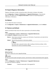
.... Go to the factory default. Default Reset all the parameters are reset to the default settings. 9.8 Upgrade Before You Start You need to the default settings. Go to upgrade. Steps 1. Note Be careful when using this function. Choose one method to Configuration → System → Maintenance → Upgrade & Maintenance . 2. Firmware Locate the exact path of the device. 9.6 Reboot You can reboot the device via browser. Network Camera User Manual 9.5 Export Diagnose...
.... Go to the factory default. Default Reset all the parameters are reset to the default settings. 9.8 Upgrade Before You Start You need to the default settings. Go to upgrade. Steps 1. Note Be careful when using this function. Choose one method to Configuration → System → Maintenance → Upgrade & Maintenance . 2. Firmware Locate the exact path of the device. 9.6 Reboot You can reboot the device via browser. Network Camera User Manual 9.5 Export Diagnose...
User Manual
Page 89
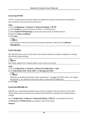
... . Set Video/Audio DSCP, Alarm DSCP and Management DSCP. It enhances the security level of data transmission. Go to Configuration → Network → Advanced Configuration → QoS . 2. Click Save. Go to Configuration → Network → Advanced Settings → 802.1X , and enable the function. The bigger the DSCP value is, the higher the priority is a port-based network access control. Protocol 72 Network Camera User Manual 9.16.4 Set HTTPS HTTPS is abnormal in router...
... . Set Video/Audio DSCP, Alarm DSCP and Management DSCP. It enhances the security level of data transmission. Go to Configuration → Network → Advanced Configuration → QoS . 2. Click Save. Go to Configuration → Network → Advanced Settings → 802.1X , and enable the function. The bigger the DSCP value is, the higher the priority is a port-based network access control. Protocol 72 Network Camera User Manual 9.16.4 Set HTTPS HTTPS is abnormal in router...

User Manual
Page 90
... router or the switch. 9.16.7 Control Timeout Settings If this function is a cryptographic network protocol for authentication. Optional: Click Export to save the log files to your computer. 9.16.9 SSH Secure Shell (SSH) is enabled, you will be configured. Network Camera User Manual EAP-LEAP, EAP-TLS, and EAP-MD5 are selectable EAP-LEAP and EAP-MD5 If you make no operation (not including viewing live image...
... router or the switch. 9.16.7 Control Timeout Settings If this function is a cryptographic network protocol for authentication. Optional: Click Export to save the log files to your computer. 9.16.9 SSH Secure Shell (SSH) is enabled, you will be configured. Network Camera User Manual EAP-LEAP, EAP-TLS, and EAP-MD5 are selectable EAP-LEAP and EAP-MD5 If you make no operation (not including viewing live image...
User Manual
Page 99
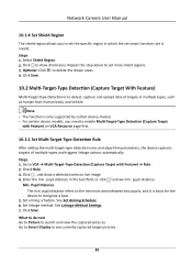
...to delete the drawn areas. 4. pupil distance. Set arming schedule. Repeat this step above to set smart function rule is only supported by certain device models. ● For certain device models, you need to enable Multi-Target-Type Detection (Capture Target with Feature) → Rule . ...Pupil Distance The min. Click Save. Network Camera User Manual 10.1.4 Set Shield Region The shield region allows you to set the specific region in which the set more shield regions. 3. Optional: Click to draw min. Steps 1. Go to Smart Display to see currently captured target pictures. 82...
...to delete the drawn areas. 4. pupil distance. Set arming schedule. Repeat this step above to set smart function rule is only supported by certain device models. ● For certain device models, you need to enable Multi-Target-Type Detection (Capture Target with Feature) → Rule . ...Pupil Distance The min. Click Save. Network Camera User Manual 10.1.4 Set Shield Region The shield region allows you to set the specific region in which the set more shield regions. 3. Optional: Click to draw min. Steps 1. Go to Smart Display to see currently captured target pictures. 82...

Quick Start Guide
Page 22
... external to the floor/wall in extremely hot, cold, dusty or wiring of the assemble, install or maintain the camera. Wear appropriate eye Set up device time manually for connection to an AC mains damp locations, and do not expose it . network. Visit the device via Web browse/client Transportation software and go to the System Security device lens. Keep the device in...
... external to the floor/wall in extremely hot, cold, dusty or wiring of the assemble, install or maintain the camera. Wear appropriate eye Set up device time manually for connection to an AC mains damp locations, and do not expose it . network. Visit the device via Web browse/client Transportation software and go to the System Security device lens. Keep the device in...