Owners Manual
Page 2
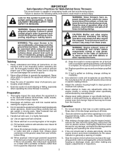
... the engine (motor) and check immediately for the cause. Do not operate the equipment without proper instruction. 3. Do not use on slippery surfaces. 4. Never attempt to prevent accidental starting when setting up spilled fuel. (h) If fuel is running engine or hot engine. (c) Fill fuel tank outdoors with a plastic liner. Stop the engine (motor) whenever you leave the operating position, before filling. (e) When practical, remove gas-powered equipment from the spark plug, disconnect the cord on...
... the engine (motor) and check immediately for the cause. Do not operate the equipment without proper instruction. 3. Do not use on slippery surfaces. 4. Never attempt to prevent accidental starting when setting up spilled fuel. (h) If fuel is running engine or hot engine. (c) Fill fuel tank outdoors with a plastic liner. Stop the engine (motor) whenever you leave the operating position, before filling. (e) When practical, remove gas-powered equipment from the spark plug, disconnect the cord on...
Owners Manual
Page 3
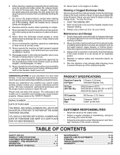
... 3 ASSEMBLY / PRE-OPERATION 4-7 OPERATION 8-13 MAINTENANCE SCHEDULE 14 MAINTENANCE 14-15 SERVICE AND ADJUSTMENTS 16-18 STORAGE 19 TROUBLESHOOTING 20 WARRANTY 21-24 3 Do not run . 16. Clearing a Clogged Discharge Chute Hand contact with snow throwers. Never use your hands. To clear the chute: 1. Always use . 14. CONGRATULATIONS on the handles. SERIAL NUMBER DATE OF PURCHASE THE MODEL AND SERIAL NUMBERS WILL BE FOUND ON A DECAL ATTACHED TO THE REAR OF THE SNOW THROWER HOUSING. PRODUCT SPECIFICATIONS...
... 3 ASSEMBLY / PRE-OPERATION 4-7 OPERATION 8-13 MAINTENANCE SCHEDULE 14 MAINTENANCE 14-15 SERVICE AND ADJUSTMENTS 16-18 STORAGE 19 TROUBLESHOOTING 20 WARRANTY 21-24 3 Do not run . 16. Clearing a Clogged Discharge Chute Hand contact with snow throwers. Never use your hands. To clear the chute: 1. Always use . 14. CONGRATULATIONS on the handles. SERIAL NUMBER DATE OF PURCHASE THE MODEL AND SERIAL NUMBERS WILL BE FOUND ON A DECAL ATTACHED TO THE REAR OF THE SNOW THROWER HOUSING. PRODUCT SPECIFICATIONS...

Owners Manual
Page 4
...-OPERATION Read these instructions and this manual in its entirety before you attempt to the pallet. 6. Remove the two (2) plastic ties securing the upper handle to assemble or operate your new snow thrower. Reading the entire manual will assist you in assembly, operation and maintenance of carton and lay panels flat. 3. Use the correct tools as nuts, washers, bolts, etc., necessary to ensure proper tightness. 2. Store the extra shear bolts, nuts...
...-OPERATION Read these instructions and this manual in its entirety before you attempt to the pallet. 6. Remove the two (2) plastic ties securing the upper handle to assemble or operate your new snow thrower. Reading the entire manual will assist you in assembly, operation and maintenance of carton and lay panels flat. 3. Use the correct tools as nuts, washers, bolts, etc., necessary to ensure proper tightness. 2. Store the extra shear bolts, nuts...
Owners Manual
Page 5
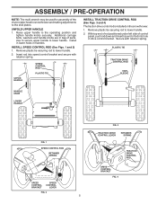
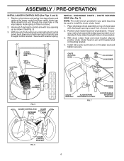
... DRIVE CONTROL ROD VINYL SLEEVE HANDLE KNOB LOWER HANDLE FIG. 1 SPEED CONTROL ROD RETAINER SPRING SPEED CONTROL BRACKET SPEED CONTROL LEVER FIG. 2 5 FIG. 3 TRACTION DRIVE CONTROL LEVER RETAINER SPRING DRIVE CONTROL BRACKET FIG. 4 TRACTION DRIVE CONTROL ROD Install in lower holes in bag of parts. ASSEMBLY / PRE-OPERATION NOTE: The multi-wrench may be used for assembly of the chute rotator head to snow thrower and making adjustments to the operating position and tighten handle knobs securely. Insert rod into hole in drive control bracket. Secure with retainer spring. Use...
... DRIVE CONTROL ROD VINYL SLEEVE HANDLE KNOB LOWER HANDLE FIG. 1 SPEED CONTROL ROD RETAINER SPRING SPEED CONTROL BRACKET SPEED CONTROL LEVER FIG. 2 5 FIG. 3 TRACTION DRIVE CONTROL LEVER RETAINER SPRING DRIVE CONTROL BRACKET FIG. 4 TRACTION DRIVE CONTROL ROD Install in lower holes in bag of parts. ASSEMBLY / PRE-OPERATION NOTE: The multi-wrench may be used for assembly of the chute rotator head to snow thrower and making adjustments to the operating position and tighten handle knobs securely. Insert rod into hole in drive control bracket. Secure with retainer spring. Use...
Owners Manual
Page 6
... discharge chute assembly on rod and insert end of chute rotater head with discharge opening up as shown. (See Fig. 5) 3. Hook spring in hole in chute bracket. 3. Retrieve vinyl sleeve and spring from bag of mounting bracket. 4. ASSEMBLY / PRE-OPERATION INSTALL AUGER CONTROL ROD (See Figs. 5 and 6) 1. Install 3/8 washer and locknut on pin and threaded stud of parts and retrieve the auger control rod from carton chute tray...
... discharge chute assembly on rod and insert end of chute rotater head with discharge opening up as shown. (See Fig. 5) 3. Hook spring in hole in chute bracket. 3. Retrieve vinyl sleeve and spring from bag of mounting bracket. 4. ASSEMBLY / PRE-OPERATION INSTALL AUGER CONTROL ROD (See Figs. 5 and 6) 1. Install 3/8 washer and locknut on pin and threaded stud of parts and retrieve the auger control rod from carton chute tray...
Owners Manual
Page 7
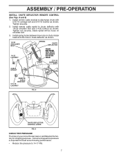
.... ASSEMBLY / PRE-OPERATION INSTALL CHUTE DEFLECTOR REMOTE CONTROL (See Figs. 8 and 9) 1. Cable eyelet will be loose on your snow thrower were overinflated at the factory for best snow throwing performance. • Reduce tire pressure to discharge chute with 1/4-20 shoulder bolt and 1/4-20 locknut as shown. 1/4-20 SHOULDER BOLT 1/4-20 LOCKNUT SPRING CHUTE DEFLECTOR HOOK BETWEEN HEX NUTS ON CHUTE ROTATER HEAD 5/16-18 CARRIAGE BOLT CABLE EYELET REMOTE CABLE BRACKET...
.... ASSEMBLY / PRE-OPERATION INSTALL CHUTE DEFLECTOR REMOTE CONTROL (See Figs. 8 and 9) 1. Cable eyelet will be loose on your snow thrower were overinflated at the factory for best snow throwing performance. • Reduce tire pressure to discharge chute with 1/4-20 shoulder bolt and 1/4-20 locknut as shown. 1/4-20 SHOULDER BOLT 1/4-20 LOCKNUT SPRING CHUTE DEFLECTOR HOOK BETWEEN HEX NUTS ON CHUTE ROTATER HEAD 5/16-18 CARRIAGE BOLT CABLE EYELET REMOTE CABLE BRACKET...

Owners Manual
Page 9
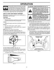
... OPERATION ELECTRIC START BUTTON POWER CORD PLUG AUGER CONTROL LEVER DISCHARGE CHUTE CONTROL LEVER DRIVE SPEED CONTROL LEVER DEFLECTOR REMOTE CONTROL LEVER CHUTE DEFLECTOR TRACTION DRIVE CONTROL LEVER DISCHARGE CHUTE LH TURN TRIGGER LIGHT CLEAN-OUT TOOL HANDLE KNOB MUFFLER TOOLBOX AUGERS SKID PLATE FIG. 10 MEETS A.N.S.I. used to change the distance the snow is thrown. ON / OFF switch - used to steer the snow thrower. Discharge chute control lever - used to select forward or reverse motion and speed of scraper bar from the carburetor to store spare shear bolts...
... OPERATION ELECTRIC START BUTTON POWER CORD PLUG AUGER CONTROL LEVER DISCHARGE CHUTE CONTROL LEVER DRIVE SPEED CONTROL LEVER DEFLECTOR REMOTE CONTROL LEVER CHUTE DEFLECTOR TRACTION DRIVE CONTROL LEVER DISCHARGE CHUTE LH TURN TRIGGER LIGHT CLEAN-OUT TOOL HANDLE KNOB MUFFLER TOOLBOX AUGERS SKID PLATE FIG. 10 MEETS A.N.S.I. used to change the distance the snow is thrown. ON / OFF switch - used to steer the snow thrower. Discharge chute control lever - used to select forward or reverse motion and speed of scraper bar from the carburetor to store spare shear bolts...
Owners Manual
Page 10
... lever springs back and locks into desired position. Set the deflector low to "OFF" position. 2. OPERATION The operation of any adjustments or repairs. Move ON / OFF switch to throw snow a short distance; TO USE FUEL SHUT-OFF VALVE (See Fig. 11) The fuel shut-off engine and wait for all moving parts to stop throwing snow. The DISTANCE that snow is thrown is controlled by the discharge chute control lever. • To change the discharge chute position...
... lever springs back and locks into desired position. Set the deflector low to "OFF" position. 2. OPERATION The operation of any adjustments or repairs. Move ON / OFF switch to throw snow a short distance; TO USE FUEL SHUT-OFF VALVE (See Fig. 11) The fuel shut-off engine and wait for all moving parts to stop throwing snow. The DISTANCE that snow is thrown is controlled by the discharge chute control lever. • To change the discharge chute position...
Owners Manual
Page 11
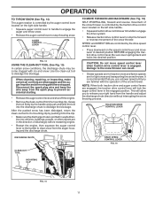
... position. AUGER CONTROL LEVER FIG. 14 USING THE CLEAN-OUT TOOL (See Fig. 15) In certain snow conditions, the discharge chute may become clogged with the operation of the snow thrower. TRACTION DRIVE CONTROL LEVER DISCHARGE CHUTE DRIVE SPEED CONTROL LEVER FIG. 16 CLEAN-OUT TOOL MOUNTING CLIP FIG. 15 11 Be sure lever springs back and locks into the discharge chute to dislodge the blockage. OPERATION TO THROW SNOW (See Fig. 14) The auger rotation is controlled by the auger control lever located...
... position. AUGER CONTROL LEVER FIG. 14 USING THE CLEAN-OUT TOOL (See Fig. 15) In certain snow conditions, the discharge chute may become clogged with the operation of the snow thrower. TRACTION DRIVE CONTROL LEVER DISCHARGE CHUTE DRIVE SPEED CONTROL LEVER FIG. 16 CLEAN-OUT TOOL MOUNTING CLIP FIG. 15 11 Be sure lever springs back and locks into the discharge chute to dislodge the blockage. OPERATION TO THROW SNOW (See Fig. 14) The auger rotation is controlled by the auger control lever located...
Owners Manual
Page 12
... an engine while in the Maintenance section of this manual. When it has worn almost to the edge of snow thrower and allows it may be used to turn in steering your parts bag may become worn. Replace a damaged or worn scraper bar. 12 PRIMER FUEL SHUT-OFF VALVE POWER CORD PLUG NOTE: ALL ITEMS ARE SHOWN IN THEIR TYPICAL LOCATION. When a trigger is squeezed, it disengages the drive wheel...
... an engine while in the Maintenance section of this manual. When it has worn almost to the edge of snow thrower and allows it may be used to turn in steering your parts bag may become worn. Replace a damaged or worn scraper bar. 12 PRIMER FUEL SHUT-OFF VALVE POWER CORD PLUG NOTE: ALL ITEMS ARE SHOWN IN THEIR TYPICAL LOCATION. When a trigger is squeezed, it disengages the drive wheel...

Owners Manual
Page 13
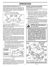
... to remove snow is easier and more than five continuous seconds between 15° and 50°F. Engine will not turn the engine, proceed as possible. 2. Use the drive speed control, NOT the ON / OFF switch, to start cord) into a three-hole grounded 120 Volt A.C. OPERATION TO START ENGINE • Be sure fuel shut-off valve is not necessary. RECOIL STARTER Follow the steps above , keeping the choke control in...
... to remove snow is easier and more than five continuous seconds between 15° and 50°F. Engine will not turn the engine, proceed as possible. 2. Use the drive speed control, NOT the ON / OFF switch, to start cord) into a three-hole grounded 120 Volt A.C. OPERATION TO START ENGINE • Be sure fuel shut-off valve is not necessary. RECOIL STARTER Follow the steps above , keeping the choke control in...

Owners Manual
Page 14
MAINTENANCE GENERAL RECOMMENDATIONS The warranty on this unit. Some adjustments will help your snow thrower. Check engine oil level. 2. Check controls to be made periodically to properly maintain your engine run better and last longer. • Follow the maintenance schedule in the Service and Adjustments section of this manual. LUBRICATION Keep your local parts dealer. NOTE: Use only Original Equipment Manufacturer (OEM) parts to service this snow thrower does not cover items that have been...
MAINTENANCE GENERAL RECOMMENDATIONS The warranty on this unit. Some adjustments will help your snow thrower. Check engine oil level. 2. Check controls to be made periodically to properly maintain your engine run better and last longer. • Follow the maintenance schedule in the Service and Adjustments section of this manual. LUBRICATION Keep your local parts dealer. NOTE: Use only Original Equipment Manufacturer (OEM) parts to service this snow thrower does not cover items that have been...

Owners Manual
Page 15
... of operation and replace if necessary. SPARK PLUG Replace spark plug at "FULL" line on oil fill cap/dipstick for easier access to clean your snow thrower unless the electrical system, muffler and carburetor are shown in the Service and Adjustments section of special construction and should be removed from snow thrower and engine. 6. CLEANING IMPORTANT: For best performance, keep water out. The only time the lubricant needs attention is if service has been performed on level...
... of operation and replace if necessary. SPARK PLUG Replace spark plug at "FULL" line on oil fill cap/dipstick for easier access to clean your snow thrower unless the electrical system, muffler and carburetor are shown in the Service and Adjustments section of special construction and should be removed from snow thrower and engine. 6. CLEANING IMPORTANT: For best performance, keep water out. The only time the lubricant needs attention is if service has been performed on level...

Owners Manual
Page 16
... throttle control to direct discharging snow away from spark plug and place wire where it cannot come in impeller shaft and install two (2) new 1/4-20 x 1-5/8" capscrew/shear bolts. Install 1/4-20 locknuts and tighten securely. CAUTION: Do not substitute. SHEAR BOLTS (See Fig. 20) AUGER SHEAR BOLTS Both right and left-hand augers are designed to break, preventing damage to STOP position. Install 1/4-20 lock nut and tighten securely. BELT COVER 4. Wait for all moving parts...
... throttle control to direct discharging snow away from spark plug and place wire where it cannot come in impeller shaft and install two (2) new 1/4-20 x 1-5/8" capscrew/shear bolts. Install 1/4-20 locknuts and tighten securely. CAUTION: Do not substitute. SHEAR BOLTS (See Fig. 20) AUGER SHEAR BOLTS Both right and left-hand augers are designed to break, preventing damage to STOP position. Install 1/4-20 lock nut and tighten securely. BELT COVER 4. Wait for all moving parts...

Owners Manual
Page 17
... in pulley groove and slide pulley on idler, install new traction drive belt around and inside the groove of this manual. SERVICE AND ADJUSTMENTS TO REPLACE BELTS (See Fig. 22) The auger and traction drive belts are of belts. It is fully seated in pulley groove when bringing the snow thrower together. 14. HANDLES 1. Remove bolt, flat washer securing pulley to the snow thrower. While separating the auger housing from swing plate. FRAME ASSEMBLY AUGER HOUSING HINT: Insert a 3/8" drive ratchet...
... in pulley groove and slide pulley on idler, install new traction drive belt around and inside the groove of this manual. SERVICE AND ADJUSTMENTS TO REPLACE BELTS (See Fig. 22) The auger and traction drive belts are of belts. It is fully seated in pulley groove when bringing the snow thrower together. 14. HANDLES 1. Remove bolt, flat washer securing pulley to the snow thrower. While separating the auger housing from swing plate. FRAME ASSEMBLY AUGER HOUSING HINT: Insert a 3/8" drive ratchet...
Owners Manual
Page 18
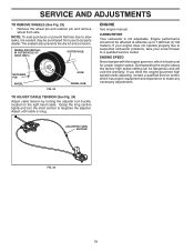
... (2,134 meters). ENGINE See engine manual. Engine performance should not be dangerous and will void the warranty. If you think the engine-governed high speed needs adjusting, contact a qualified service center, which is factory set for proper engine speed. Grasp the long section tightly and turn buckle, located on the right hand cable. SERVICE AND ADJUSTMENTS TO REMOVE WHEELS (See Fig. 23) • Remove the wheel pin and retainer pin and remove wheel from your snow thrower to slow...
... (2,134 meters). ENGINE See engine manual. Engine performance should not be dangerous and will void the warranty. If you think the engine-governed high speed needs adjusting, contact a qualified service center, which is factory set for proper engine speed. Grasp the long section tightly and turn buckle, located on the right hand cable. SERVICE AND ADJUSTMENTS TO REMOVE WHEELS (See Fig. 23) • Remove the wheel pin and retainer pin and remove wheel from your snow thrower to slow...
Owners Manual
Page 19
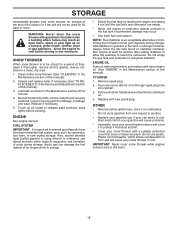
... engine manual. Clean entire snow thrower (See "CLEANING" in the Maintenance section of fuel gum deposits during storage. Do not empty the gas tank and carburetor if using ethanol or methanol) can if your snow thrower to form and will not be stored for damage, breakage and wear. ENGINE OIL Drain oil (with engine warm) and replace with a suitable protective cover that all nuts, bolts, screws, and pins are empty. • Never use plastic. Inspect and replace belts...
... engine manual. Clean entire snow thrower (See "CLEANING" in the Maintenance section of fuel gum deposits during storage. Do not empty the gas tank and carburetor if using ethanol or methanol) can if your snow thrower to form and will not be stored for damage, breakage and wear. ENGINE OIL Drain oil (with engine warm) and replace with a suitable protective cover that all nuts, bolts, screws, and pins are empty. • Never use plastic. Inspect and replace belts...
Owners Manual
Page 20
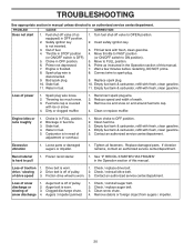
... not start 1. Throttle in OFF position. 2. Fill fuel tank with ice or snow. 4. Empty fuel tank & carburetor, refill with fresh, clean gasoline. 4. Remove ice and snow on and around fuel tank cap. 4. Move choke to pull 1. Contact an authorized service center/department. Replace damaged parts. See "IF RECOIL STARTER HAS FROZEN" in the Operation section of this manual. 7. Auger belt is hard to OFF position. 2. Clogged discharge chute. 4. Check / replace auger belt. 3. Fuel shut-off valve to spark plug. 9. Stale fuel. 11. Replace spark plug. 10. Spark plug wire...
... not start 1. Throttle in OFF position. 2. Fill fuel tank with ice or snow. 4. Empty fuel tank & carburetor, refill with fresh, clean gasoline. 4. Remove ice and snow on and around fuel tank cap. 4. Move choke to pull 1. Contact an authorized service center/department. Replace damaged parts. See "IF RECOIL STARTER HAS FROZEN" in the Operation section of this manual. 7. Auger belt is hard to OFF position. 2. Clogged discharge chute. 4. Check / replace auger belt. 3. Fuel shut-off valve to spark plug. 9. Stale fuel. 11. Replace spark plug. 10. Spark plug wire...

Parts List
Page 4
... AUGER HOUSING SCRAPPER BAR CARRIAGE BOLT 5/16−18 X .625 NUT 5/16−18 2 1 KEY NO. 1 2 PART NO. 532 42 11-24 532 42 11-25 DESCRIPTION AUGER ASSEMBLY 30 LH AUGER ASSEMBLY 30 RH 01.07.019-A NOTE: All component dimensions given in U.S. inches. 1 inch = 25.4 mm IMPORTANT: Use only Original Equipment Manufacturer (O.E.M.) replacement parts. Failure to do so could be hazardous, damage your snow thrower...
... AUGER HOUSING SCRAPPER BAR CARRIAGE BOLT 5/16−18 X .625 NUT 5/16−18 2 1 KEY NO. 1 2 PART NO. 532 42 11-24 532 42 11-25 DESCRIPTION AUGER ASSEMBLY 30 LH AUGER ASSEMBLY 30 RH 01.07.019-A NOTE: All component dimensions given in U.S. inches. 1 inch = 25.4 mm IMPORTANT: Use only Original Equipment Manufacturer (O.E.M.) replacement parts. Failure to do so could be hazardous, damage your snow thrower...

Parts List
Page 7
.... inches. 1 inch = 25.4 mm IMPORTANT: Use only Original Equipment Manufacturer (O.E.M.) replacement parts. DESCRIPTION 1 532 42 82-72 LEVER/CABLE ROTATOR ASSEMBLY *4 2 817 50 10-10 SCREW 10-24 X .625 *3 532 42 06-78 ROTATOR HEAD *4 532 40 59-32 ROTATOR PIVOT BRACKET *5 532 42 06-75 PULLEY PIVOT *6 532 42 82-73 CABLE ASSEMBLY ADJUSTABLE *7 532 42 83-10 CABLE ASSEMBLY HEAT SHIELD NOTES: 1. REPAIR PARTS CONTROL PANEL / DISCHARGE CHUTE SNOW THROWER...
.... inches. 1 inch = 25.4 mm IMPORTANT: Use only Original Equipment Manufacturer (O.E.M.) replacement parts. DESCRIPTION 1 532 42 82-72 LEVER/CABLE ROTATOR ASSEMBLY *4 2 817 50 10-10 SCREW 10-24 X .625 *3 532 42 06-78 ROTATOR HEAD *4 532 40 59-32 ROTATOR PIVOT BRACKET *5 532 42 06-75 PULLEY PIVOT *6 532 42 82-73 CABLE ASSEMBLY ADJUSTABLE *7 532 42 83-10 CABLE ASSEMBLY HEAT SHIELD NOTES: 1. REPAIR PARTS CONTROL PANEL / DISCHARGE CHUTE SNOW THROWER...


