

Parts Manual
Page 17
..., (150 m) 1 Wire (250 m) 1 Wire (500 m) 1 Wire (800 m) 1 Power Supply Unit EU 1 Power Supply Unit UK, IE 1 EU 1 Power Supply Unit CH 1 Power Supply Unit US, CA 1 Power Supply Unit AU, NZ 1 Power Supply Unit JP 1 Measuring Tape 1 Low voltage cable 20m 1 Low voltage cable 10m 1 Low voltage cable 3m 1 Low Voltage Cable (5 m) 1 6 pcs+Key 1 Sticker, Cable Markers, 10 pcs 1 Label Alarm 1 Cable Connector Protection 1 1 INSTALLATION ACCESSORIES Ref Part No...
..., (150 m) 1 Wire (250 m) 1 Wire (500 m) 1 Wire (800 m) 1 Power Supply Unit EU 1 Power Supply Unit UK, IE 1 EU 1 Power Supply Unit CH 1 Power Supply Unit US, CA 1 Power Supply Unit AU, NZ 1 Power Supply Unit JP 1 Measuring Tape 1 Low voltage cable 20m 1 Low voltage cable 10m 1 Low voltage cable 3m 1 Low Voltage Cable (5 m) 1 6 pcs+Key 1 Sticker, Cable Markers, 10 pcs 1 Label Alarm 1 Cable Connector Protection 1 1 INSTALLATION ACCESSORIES Ref Part No...

Owner Manual
Page 1
Operator's manual HUSQVARNA AUTOMOWER® 310/315/315X Read the operator's manual carefully and make sure that you understand the instructions before you use the product. EN, English
Operator's manual HUSQVARNA AUTOMOWER® 310/315/315X Read the operator's manual carefully and make sure that you understand the instructions before you use the product. EN, English
Owner Manual
Page 2
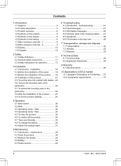
... 10 1.10 Keypad 10 2 Safety 2.1 Safety definitions 11 2.2 General safety instructions 11 2.3 Safety instructions for operation 13 3 Installation 3.1 Introduction - Park 35 4.5 To stop the product 35 4.6 To switch off the product 35 4.7 Timer and Standby 35 4.8 To charge the battery 36 4.9 Adjust the cutting height 37 5 Maintenance 5.1 Introduction - Start 34 4.4 Operating mode - Installation 16 3.2 Before the installation of the wires........... 16 3.3 Before the installation of the product........16 3.4 Installation of the product 21...
... 10 1.10 Keypad 10 2 Safety 2.1 Safety definitions 11 2.2 General safety instructions 11 2.3 Safety instructions for operation 13 3 Installation 3.1 Introduction - Park 35 4.5 To stop the product 35 4.6 To switch off the product 35 4.7 Timer and Standby 35 4.8 To charge the battery 36 4.9 Adjust the cutting height 37 5 Maintenance 5.1 Introduction - Start 34 4.4 Operating mode - Installation 16 3.2 Before the installation of the wires........... 16 3.3 Before the installation of the product........16 3.4 Installation of the product 21...
Owner Manual
Page 4
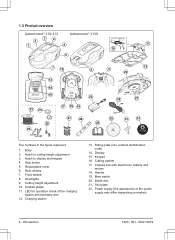
Body 2. Rear wheels 7. LED for operation check of the power supply may differ depending on market) 4 - Main switch 20. Cutting height adjustment 10. Rating plate (incl. Display 15. Cutting system 17. Hatch to cutting height adjustment 3. Headlights 9. Chassis box with electronics, battery and motors 18. Skid plate 22. Keypad 16. Stop button 5. Introduction 1220 - 001 - 08.07.2019 1.3 Product overview Automower® 310/315 Automower® 315X 34 2 1 5 11...
Body 2. Rear wheels 7. LED for operation check of the power supply may differ depending on market) 4 - Main switch 20. Cutting height adjustment 10. Rating plate (incl. Display 15. Cutting system 17. Hatch to cutting height adjustment 3. Headlights 9. Chassis box with electronics, battery and motors 18. Skid plate 22. Keypad 16. Stop button 5. Introduction 1220 - 001 - 08.07.2019 1.3 Product overview Automower® 310/315 Automower® 315X 34 2 1 5 11...
Owner Manual
Page 5
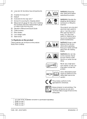
... product's emissions are set to surroundings. Use a detachable power supply as defined on the machine. Extra blades 32. WARNING: Read the user instructions before operating the product. Cable markers 31. The product can be found on the rating plate. 1 Is a part of the Installation kit which is broken loose from the machine when operating. 23. Connector for boundary loop and guide wire 1 24. Low voltage...
... product's emissions are set to surroundings. Use a detachable power supply as defined on the machine. Extra blades 32. WARNING: Read the user instructions before operating the product. Cable markers 31. The product can be found on the rating plate. 1 Is a part of the Installation kit which is broken loose from the machine when operating. 23. Connector for boundary loop and guide wire 1 24. Low voltage...
Owner Manual
Page 6
... product cuts the lawn. Operate the disabling device before you use a trimmer nearby the low voltage cable. Flashes as normal household waste. Read the user instructions. 6 - The chassis contains components which are placed. A broken seal can result in ECO-mode. The product will not cut the grass do not charge the battery. 1.5 Symbols on the battery The installation function for manual settings for the problems. The...
... product cuts the lawn. Operate the disabling device before you use a trimmer nearby the low voltage cable. Flashes as normal household waste. Read the user instructions. 6 - The chassis contains components which are placed. A broken seal can result in ECO-mode. The product will not cut the grass do not charge the battery. 1.5 Symbols on the battery The installation function for manual settings for the problems. The...

Owner Manual
Page 14
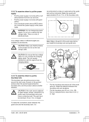
... the instructions. run simultaneously. Be careful, especially if the product is set the timer on top of electrical/mechanical • The product must never be used with a defective guard, blade disc or body. Too high 14 - Safety 1220 - 001 - 08.07.2019 Neither should it around when the main switch is in alarm is very loud. Set the main switch in use the...
... the instructions. run simultaneously. Be careful, especially if the product is set the timer on top of electrical/mechanical • The product must never be used with a defective guard, blade disc or body. Too high 14 - Safety 1220 - 001 - 08.07.2019 Neither should it around when the main switch is in alarm is very loud. Set the main switch in use the...
Owner Manual
Page 17
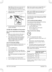
...charging station plate. 3.3.2 To examine where to put the power supply • Put the power supply in an area with a roof and protection from the sun and rain. • Put the power supply in an area with good airflow. • Use a residual-current device (RCD) when you install the boundary wire and guide wire...cm / 8 in. high. Make the eyelet with the signal from an obstacle that the blades on the product do not cut or extend the lowvoltage cable. E D F C A 3.3.3 To examine where to the power outlet. Adapt the distance between the guide wire and the boundary wire, it is a ...
...charging station plate. 3.3.2 To examine where to put the power supply • Put the power supply in an area with a roof and protection from the sun and rain. • Put the power supply in an area with good airflow. • Use a residual-current device (RCD) when you install the boundary wire and guide wire...cm / 8 in. high. Make the eyelet with the signal from an obstacle that the blades on the product do not cut or extend the lowvoltage cable. E D F C A 3.3.3 To examine where to the power outlet. Adapt the distance between the guide wire and the boundary wire, it is a ...

Owner Manual
Page 20
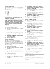
...a secondary area (D), refer to To make sharp bends when you install the guide wire. • If the work area has areas which the product uses to find the charging station. The settings can set the corridor width of the guide wire A The guide corridor is at a minimum 3 m / 10 ft. If the... ft. Refer to the boundary wire 3. Installation 1220 - 001 - 08.07.2019 to To set the Lawn coverage function on page 26. • Use the GPS Assisted Navigation. from the boundary wire. • Do not make a secondary area on page 34. 20 - Do steps 1-3 in . Push the BACK button. Note: Make ...
...a secondary area (D), refer to To make sharp bends when you install the guide wire. • If the work area has areas which the product uses to find the charging station. The settings can set the corridor width of the guide wire A The guide corridor is at a minimum 3 m / 10 ft. If the... ft. Refer to the boundary wire 3. Installation 1220 - 001 - 08.07.2019 to To set the Lawn coverage function on page 26. • Use the GPS Assisted Navigation. from the boundary wire. • Do not make a secondary area on page 34. 20 - Do steps 1-3 in . Push the BACK button. Note: Make ...
Owner Manual
Page 23
... code on page 3. 6. Put the boundary wire or the guide wire into position with a Automower® 310. 1220 - 001 - 08.07.2019 Installation - 23 Push the STOP button. 2. Push the MENU button. 3.9.2 To do the product settings The product has factory settings but the settings can be adapted to the number of the lawn with an adjustable pliers. Note: The operation capacity is approximate and timer settings can be adjusted...
... code on page 3. 6. Put the boundary wire or the guide wire into position with a Automower® 310. 1220 - 001 - 08.07.2019 Installation - 23 Push the STOP button. 2. Push the MENU button. 3.9.2 To do the product settings The product has factory settings but the settings can be adapted to the number of the lawn with an adjustable pliers. Note: The operation capacity is approximate and timer settings can be adjusted...
Owner Manual
Page 30
.... 5. Push the BACK button. 3.9.10.4 Slope control In order to decrease lawn wear near the boundary wire in slopes, the product prevents to changes in To get access to move through the menu structure Settings > Spiral Cutting > Use Spiral Cutting > Intensity. 3. Use the arrow buttons and the OK button to set in 5 levels: • Low• Low • Mid • High • High+ The level sets...
.... 5. Push the BACK button. 3.9.10.4 Slope control In order to decrease lawn wear near the boundary wire in slopes, the product prevents to changes in To get access to move through the menu structure Settings > Spiral Cutting > Use Spiral Cutting > Intensity. 3. Use the arrow buttons and the OK button to set in 5 levels: • Low• Low • Mid • High • High+ The level sets...
Owner Manual
Page 31
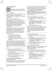
... you are in the operational area. Follow the instructions in the app. 1220 - 001 - 08.07.2019 Installation - 31 To remove paired accounts 1. To pair Automower® Connect and the product 1. This means that have connection with your Husqvarna account in the Automower® Connect app. 3.9.11.3 Automower® Connect@Home (Automower® 310/315) Connect@Home uses a short-range Bluetooth...
... you are in the operational area. Follow the instructions in the app. 1220 - 001 - 08.07.2019 Installation - 31 To remove paired accounts 1. To pair Automower® Connect and the product 1. This means that have connection with your Husqvarna account in the Automower® Connect app. 3.9.11.3 Automower® Connect@Home (Automower® 310/315) Connect@Home uses a short-range Bluetooth...
Owner Manual
Page 34
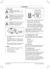
... message Needs manual charging shows in the work , inspection or maintenance is empty. 4 Operation 4.1 Main switch WARNING: Read the safety instructions carefully before any work area. 5. When the battery is not in the 1 position to charge the battery. Select the desired operating mode. WARNING: Keep your hands or feet close to cut. 34 - Enter the PIN code. 4. Put the product in the charging station to start...
... message Needs manual charging shows in the work , inspection or maintenance is empty. 4 Operation 4.1 Main switch WARNING: Read the safety instructions carefully before any work area. 5. When the battery is not in the 1 position to charge the battery. Select the desired operating mode. WARNING: Keep your hands or feet close to cut. 34 - Enter the PIN code. 4. Put the product in the charging station to start...
Owner Manual
Page 36
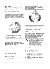
... periods to prevent mowing when there usually is intended for a long period, the battery can be empty and needs to be according to the Standby time table. If the timer setting is parked in standby mode in the charging station from the battery. WARNING: Only charge the product using a charging station and a power supply which is other activities ongoing. Operation 1220 - 001...
... periods to prevent mowing when there usually is intended for a long period, the battery can be empty and needs to be according to the Standby time table. If the timer setting is parked in standby mode in the charging station from the battery. WARNING: Only charge the product using a charging station and a power supply which is other activities ongoing. Operation 1220 - 001...

Owner Manual
Page 38
... with blunt blades gives a poorer mowing result. Set the Main switch to 6 weeks when used under favorable conditions. The edges of the blades should not be necessary to replace the blades. The normal life is recommended to disconnect the charging station before any maintenance, or cleaning of objects such as well with slopes. Husqvarna offers a special cleaning and maintenance kit as the rear wheel bracket. Lift...
... with blunt blades gives a poorer mowing result. Set the Main switch to 6 weeks when used under favorable conditions. The edges of the blades should not be necessary to replace the blades. The normal life is recommended to disconnect the charging station before any maintenance, or cleaning of objects such as well with slopes. Husqvarna offers a special cleaning and maintenance kit as the rear wheel bracket. Lift...
Owner Manual
Page 41
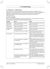
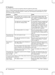
..., a number of malfunction or symptoms can guide you if the product does not work area. Action Check the drive wheel and remove the grass or other object has wrapped around the drive wheel. Cutting system blocked Grass or other object. No loop signal The power supply is a malfunction. Check that the boundary wire connectors are fitted properly to the charging station. Boundary wire broken. Refer to start outside...
..., a number of malfunction or symptoms can guide you if the product does not work area. Action Check the drive wheel and remove the grass or other object has wrapped around the drive wheel. Cutting system blocked Grass or other object. No loop signal The power supply is a malfunction. Check that the boundary wire connectors are fitted properly to the charging station. Boundary wire broken. Refer to start outside...
Owner Manual
Page 44
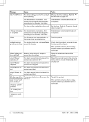
... drive wheel. Alarm! lem, front/rear Charging system problem Tilt sensor problem Temporary problem Action Change the timer settings. Free the product Check that the product body can not move freely around the wheels. Troubleshooting 1220 - 001 - 08.07.2019 Message Next start hh:mm Cause The timer setting prevents the product from operating. Mower stopped The alarm was activated because the product was lifted. The day's mowing...
... drive wheel. Alarm! lem, front/rear Charging system problem Tilt sensor problem Temporary problem Action Change the timer settings. Free the product Check that the product body can not move freely around the wheels. Troubleshooting 1220 - 001 - 08.07.2019 Message Next start hh:mm Cause The timer setting prevents the product from operating. Mower stopped The alarm was activated because the product was lifted. The day's mowing...
Owner Manual
Page 48
... the charging station. Refer to To install the guide wire on page 21 The guide wire is entirely level. Refer to To install the charging station on page 22. at lead to To set the timer on page 39. The start time and stop times for mowing are of Husq- Refer to the instructions. Check if the blades are incorrect. The product runs, but the blade disc...
... the charging station. Refer to To install the guide wire on page 21 The guide wire is entirely level. Refer to To install the charging station on page 22. at lead to To set the timer on page 39. The start time and stop times for mowing are of Husq- Refer to the instructions. Check if the blades are incorrect. The product runs, but the blade disc...

Owner Manual
Page 49
... the set the level of the loop wire can damage wire insulation. START button first being stretched excessively during installation. Refer to limit the work area or extend the work area. and charging times are usually the result of the work time. The product is spent. ton and then close the hatch. Uneven mowing results. Adjust how often the Spiral Cutting...
... the set the level of the loop wire can damage wire insulation. START button first being stretched excessively during installation. Refer to limit the work area or extend the work area. and charging times are usually the result of the work time. The product is spent. ton and then close the hatch. Uneven mowing results. Adjust how often the Spiral Cutting...
Owner Manual
Page 54
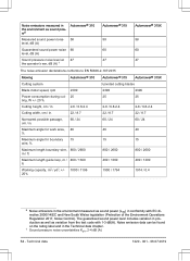
...Mowing Automower® 310 Cutting system Blade motor speed, rpm 2300 Power consumption during cut- 25 ting, W +/- 20 % Cutting height, cm / in. 2-6 / 0.8-2.4 Cutting width, cm / in. 22 / 8.7 Narrowest possible passage, cm / in. 60 / 24 Maximum angle for work area, 40 % Maximum angle for boundary 15 wire, % Maximum length boundary wire, 800 / 2600 m / ft Maximum length guide loop, m / 400 / 1300 ft Working capacity... from the test code with EC directive 2000/14/EC and New South Wales legislation (Protection of the Environment Operations Regulation 2017, Noise Control).
...Mowing Automower® 310 Cutting system Blade motor speed, rpm 2300 Power consumption during cut- 25 ting, W +/- 20 % Cutting height, cm / in. 2-6 / 0.8-2.4 Cutting width, cm / in. 22 / 8.7 Narrowest possible passage, cm / in. 60 / 24 Maximum angle for work area, 40 % Maximum angle for boundary 15 wire, % Maximum length boundary wire, 800 / 2600 m / ft Maximum length guide loop, m / 400 / 1300 ft Working capacity... from the test code with EC directive 2000/14/EC and New South Wales legislation (Protection of the Environment Operations Regulation 2017, Noise Control).


