Operation Manual
Page 9
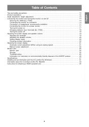
... a power source 17 Turning the power on 17 Changing between input terminals [LL-172G 18 Turning the power off 18 Adjusting the screen display and speaker volume 19 Adjusting the backlight 19 Adjusting the speaker volume 20 Setting display mode 20 Checking product information 20 Adjusting the screen display 21 Automatic screen adjustment (When using an analog signal 21 Manual screen adjustment 22 Monitor care 25 Monitor care 25 Storage 25 Troubleshooting 25 Information for customers on environmentally friendly disposal of this SHARP product 26 Specifications 27 Installing set...
... a power source 17 Turning the power on 17 Changing between input terminals [LL-172G 18 Turning the power off 18 Adjusting the screen display and speaker volume 19 Adjusting the backlight 19 Adjusting the speaker volume 20 Setting display mode 20 Checking product information 20 Adjusting the screen display 21 Automatic screen adjustment (When using an analog signal 21 Manual screen adjustment 22 Monitor care 25 Monitor care 25 Storage 25 Troubleshooting 25 Information for customers on environmentally friendly disposal of this SHARP product 26 Specifications 27 Installing set...

Operation Manual
Page 10
...a result of fire. The TFT color LCD panel used in unsafe places. Do not display a still picture for any other fluids. Do not place the monitor on it, stretch it or over may damage it may lead to the minimum setting it . - Doing so ...Use only the power cord supplied with strong shocks or vibrations. We recommend using a computer able to see the screen. - The Power Cord - Also, do not add extension cords. Do not remove or insert the power plug with hard objects. - This monitor and its accessories may be minute points on the screen where pixels never light...
...a result of fire. The TFT color LCD panel used in unsafe places. Do not display a still picture for any other fluids. Do not place the monitor on it, stretch it or over may damage it may lead to the minimum setting it . - Doing so ...Use only the power cord supplied with strong shocks or vibrations. We recommend using a computer able to see the screen. - The Power Cord - Also, do not add extension cords. Do not remove or insert the power plug with hard objects. - This monitor and its accessories may be minute points on the screen where pixels never light...

Operation Manual
Page 12
...backlight brightness and speaker volume. 5. Power terminal 11. For a digital signal input: It can be connected here. 7. Analog RGB input terminal ..... AUTO button [LL-172A This button is fixed so that it cannot be connected here. Speakers Audio entering via the external device connected to set DISPLAY MODE. 4. Security lock anchor By connecting a security lock (commercially available) to the security lock anchor, the monitor is used to the monitor can be connected here. When the OSD Menu is not displayed: This button is displayed: These buttons are used...
...backlight brightness and speaker volume. 5. Power terminal 11. For a digital signal input: It can be connected here. 7. Analog RGB input terminal ..... AUTO button [LL-172A This button is fixed so that it cannot be connected here. Speakers Audio entering via the external device connected to set DISPLAY MODE. 4. Security lock anchor By connecting a security lock (commercially available) to the security lock anchor, the monitor is used to the monitor can be connected here. When the OSD Menu is not displayed: This button is displayed: These buttons are used...

Operation Manual
Page 14
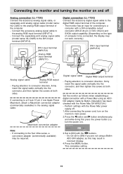
... clamp with the protrusion to a malfunction. When adjusting the viewing angle, cables may be pulled. Analog RGB terminal (Mini D-sub 15 pin, 3 row) Analog signal cable - Securing the cables [LL-172G] Use the supplied cable clamps to secure the cables connected to connector direction, firmly insert the signal cable vertically into the connector, and then tighten the screws at both the monitor and computer are switched off CAUTION! - Paying attention to the...
... clamp with the protrusion to a malfunction. When adjusting the viewing angle, cables may be pulled. Analog RGB terminal (Mini D-sub 15 pin, 3 row) Analog signal cable - Securing the cables [LL-172G] Use the supplied cable clamps to secure the cables connected to connector direction, firmly insert the signal cable vertically into the connector, and then tighten the screws at both the monitor and computer are switched off CAUTION! - Paying attention to the...
Operation Manual
Page 15
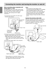
... the digital RGB output terminal of the computer. - Set the monitor as this press the power button (i.e. MAC DIGITAL INPUT-2 OFF ON OK [MENU] 3. After connecting the power cord, turn the power on). Press the MENU button. Digital connection [LL-172G] Connect the accessory digital signal cable to connector direction, firmly insert the signal cable vertically into the connector, and then tighten the screws at both sides. Macintosh conversion adapter Note: - Perform settings with the buttons. - Connect the accessory analog signal cable to [ON] with the Power Mac power supply...
... the digital RGB output terminal of the computer. - Set the monitor as this press the power button (i.e. MAC DIGITAL INPUT-2 OFF ON OK [MENU] 3. After connecting the power cord, turn the power on). Press the MENU button. Digital connection [LL-172G] Connect the accessory digital signal cable to connector direction, firmly insert the signal cable vertically into the connector, and then tighten the screws at both sides. Macintosh conversion adapter Note: - Perform settings with the buttons. - Connect the accessory analog signal cable to [ON] with the Power Mac power supply...
Operation Manual
Page 16
... sold 2-input cable (model name: NL-C03J) enables connection between the DVI-I input terminal (INPUT-2) Notes: - Mini D-sub 15 pin Audio input terminal 2-input cable (purchased separately) DVI-D 24 pin 2. Connecting the monitor and turning the monitor on and off When connecting using the 2-input cable, set the connecting input terminal [INPUT-2] to [2LINES] under Plug & Play. Paying attention to the audio output terminal of the computer, the sound of the connected computer is output from the monitor speakers. Perform...
... sold 2-input cable (model name: NL-C03J) enables connection between the DVI-I input terminal (INPUT-2) Notes: - Mini D-sub 15 pin Audio input terminal 2-input cable (purchased separately) DVI-D 24 pin 2. Connecting the monitor and turning the monitor on and off When connecting using the 2-input cable, set the connecting input terminal [INPUT-2] to [2LINES] under Plug & Play. Paying attention to the audio output terminal of the computer, the sound of the connected computer is output from the monitor speakers. Perform...

Operation Manual
Page 17
... sound can be connected. Rapid switching may need to install the monitor set to which the computer is displayed.) Note for LL-172G: - When using the LL-172G with a cable less than 3 m in malfunction. 2. When using an analog signal, perform an automatic screen adjustment under the following conditions (p.21): - When connecting to a notebook, if the notebook computer's screen is set -up green, and the screen is displayed. (After power is unnecessary. - Press power button. Using...
... sound can be connected. Rapid switching may need to install the monitor set to which the computer is displayed.) Note for LL-172G: - When using the LL-172G with a cable less than 3 m in malfunction. 2. When using an analog signal, perform an automatic screen adjustment under the following conditions (p.21): - When connecting to a notebook, if the notebook computer's screen is set -up green, and the screen is displayed. (After power is unnecessary. - Press power button. Using...

Operation Manual
Page 18
... Press power button. Turn the computer off Changing between input terminals [LL-172G] Use the INPUT button to switch between signal input terminals. Connecting the monitor and turning the monitor on and off . The power LED will not be used for a long time, turn off . 2. or When using a 2-input cable Analog RGB input terminal If the monitor will disappear. Turn the computer off the main power switch of the monitor, and remove the power plug from the outlet. Press the monitor's power button. Analog RGB input terminal DVI-I input terminal (digital) INPUT2-A INPUT...
... Press power button. Turn the computer off Changing between input terminals [LL-172G] Use the INPUT button to switch between signal input terminals. Connecting the monitor and turning the monitor on and off . The power LED will not be used for a long time, turn off . 2. or When using a 2-input cable Analog RGB input terminal If the monitor will disappear. Turn the computer off the main power switch of the monitor, and remove the power plug from the outlet. Press the monitor's power button. Analog RGB input terminal DVI-I input terminal (digital) INPUT2-A INPUT...

Operation Manual
Page 19
... to adjusted values will be used without adjustment. Note: - Adjusting the backlight 1. On Screen display for adjustment disappears several seconds after turning the power off the monitor power. 2. English Français Deutsch Italiano Adjusting the screen display and speaker volume For analog signal 1. Resetting all buttons other than the power button are disabled. Adjustment lock function By disabling the control buttons (i.e. Check that [BRIGHT] is complete when the displayed message disappears. Turn on ). Press the MENU button and the / MODE button simultaneously...
... to adjusted values will be used without adjustment. Note: - Adjusting the backlight 1. On Screen display for adjustment disappears several seconds after turning the power off the monitor power. 2. English Français Deutsch Italiano Adjusting the screen display and speaker volume For analog signal 1. Resetting all buttons other than the power button are disabled. Adjustment lock function By disabling the control buttons (i.e. Check that [BRIGHT] is complete when the displayed message disappears. Turn on ). Press the MENU button and the / MODE button simultaneously...

Operation Manual
Page 20
.... If [DISPLAY MODE] is set to [sRGB] or [VIVID], [WHITE BALANCE] is set to [0]. On Screen display for adjustment disappears several seconds after the last operation. OFFICE Display brightness is lowered. (This mode saves power.) sRGB sRGB is not displayed. STD Displays image with dynamic and vivid primary colors. - Checking product information A model name (MODEL), a serial no. (S/N), and usage time (USAGE TIME) of liquid crystal panel. Adjusting the screen display and speaker volume Adjusting the speaker volume 1. Setting display mode Color tone or brightness can...
.... If [DISPLAY MODE] is set to [sRGB] or [VIVID], [WHITE BALANCE] is set to [0]. On Screen display for adjustment disappears several seconds after the last operation. OFFICE Display brightness is lowered. (This mode saves power.) sRGB sRGB is not displayed. STD Displays image with dynamic and vivid primary colors. - Checking product information A model name (MODEL), a serial no. (S/N), and usage time (USAGE TIME) of liquid crystal panel. Adjusting the screen display and speaker volume Adjusting the speaker volume 1. Setting display mode Color tone or brightness can...
Operation Manual
Page 21
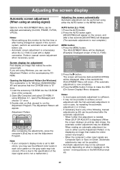
...'s video input signals are using Windows 3.1, open [File Manager] and choose "D" drive. 3. Adjustment Pattern After completing the adjustments, press the computer's [Esc] key to any of the following, manual adjustments (p.22) can be possible.) - Press the button. In such a case, try displaying an image that makes the entire screen very bright.) - Notes: - The screen will become dark and [ADJUSTING] will return. (The automatic adjustment is now complete.) MENU button 1. Press the AUTO button...
...'s video input signals are using Windows 3.1, open [File Manager] and choose "D" drive. 3. Adjustment Pattern After completing the adjustments, press the computer's [Esc] key to any of the following, manual adjustments (p.22) can be possible.) - Press the button. In such a case, try displaying an image that makes the entire screen very bright.) - Notes: - The screen will become dark and [ADJUSTING] will return. (The automatic adjustment is now complete.) MENU button 1. Press the AUTO button...
Operation Manual
Page 23
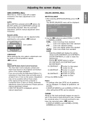
...]. - Use the / MODE button to select [COOL], [·], [STD], [·], [WARM] or [USER]. Press the MENU button. On settings other setting than [STD] can be performed. If the screen is dark and hard to have black area and white area of the image displayed. - If it is necessary to see . If [DISPLAY MODE] is set . The Auto Gain Control adjusts contrast and black level based on Green, automatic adjustment cannot be displayed. Please perform manual adjustment instead. - Color...
...]. - Use the / MODE button to select [COOL], [·], [STD], [·], [WARM] or [USER]. Press the MENU button. On settings other setting than [STD] can be performed. If the screen is dark and hard to have black area and white area of the image displayed. - If it is necessary to see . If [DISPLAY MODE] is set . The Auto Gain Control adjusts contrast and black level based on Green, automatic adjustment cannot be displayed. Please perform manual adjustment instead. - Color...
Operation Manual
Page 24
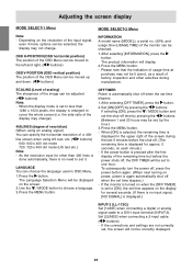
... display may be set time elapses. 1. As the resolution input for several seconds. (If there is no input signal, [NO SIGNAL] is displayed.) INPUT-2 [LL-172G] Set [1LINE] when connecting a digital or analog signal cable to the left and right. ( buttons) OSD V-POSITION (OSD vertical position) The position of a 400line screen when using US text, etc. ( buttons) 640: 640 x 400 dot mode 720: 720 x 400 dot mode (US text etc.) Note: - If selecting [ON], press the / MODE button and set...
... display may be set time elapses. 1. As the resolution input for several seconds. (If there is no input signal, [NO SIGNAL] is displayed.) INPUT-2 [LL-172G] Set [1LINE] when connecting a digital or analog signal cable to the left and right. ( buttons) OSD V-POSITION (OSD vertical position) The position of a 400line screen when using US text, etc. ( buttons) 640: 640 x 400 dot mode 720: 720 x 400 dot mode (US text etc.) Note: - If selecting [ON], press the / MODE button and set...
Operation Manual
Page 25
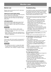
... light up orange). 25 English If using the LL-172G, confirm that [INPUT-2] is selected correctly. (p.18) - Control buttons do not work , please contact the shop where you purchased the monitor or your nearest Sharp authorized Service Center. If you are using the analog signal, perform automatic screen adjustment. (p.21) - There is suitable.) CAUTION! - LCD panel section Use a soft dry cloth to remove the power plug from the AC outlet when cleaning...
... light up orange). 25 English If using the LL-172G, confirm that [INPUT-2] is selected correctly. (p.18) - Control buttons do not work , please contact the shop where you purchased the monitor or your nearest Sharp authorized Service Center. If you are using the analog signal, perform automatic screen adjustment. (p.21) - There is suitable.) CAUTION! - LCD panel section Use a soft dry cloth to remove the power plug from the AC outlet when cleaning...

Operation Manual
Page 27
..., 3 row Digital/Analog: DVI-I 29 pin Audio input terminal Mini stereo jack Headphone terminal Mini stereo jack Height adjustment [LL-172G] Adjustment range: approx. 70 mm Screen tilt Upward approx. 0-25°; Specifications English Français Deutsch Italiano Español Product specifications Model name LL-172A-W (White)/LL-172A-B (Black) LL-172G-W (White)/LL-172G-B (Black) LCD display 43 cm measured diagonally TFT LCD module Resolution (max.) SXGA 1280 x 1024 pixels Displayable colors (max.) Approx...
..., 3 row Digital/Analog: DVI-I 29 pin Audio input terminal Mini stereo jack Headphone terminal Mini stereo jack Height adjustment [LL-172G] Adjustment range: approx. 70 mm Screen tilt Upward approx. 0-25°; Specifications English Français Deutsch Italiano Español Product specifications Model name LL-172A-W (White)/LL-172A-B (Black) LL-172G-W (White)/LL-172G-B (Black) LCD display 43 cm measured diagonally TFT LCD module Resolution (max.) SXGA 1280 x 1024 pixels Displayable colors (max.) Approx...

Operation Manual
Page 29
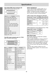
... capability can be connected here. (Depending on the type of computer to set the timing so that it is not receiving any signal (synch signal), [NO SIGNAL] will appear. English Français Deutsch Specifications Relevant signal timings (analog) Display mode VESA Hsync Vsync Dot frequency Relevant signal timings (digital) [LL-172G] Display mode VESA Hsync Dot Vsync frequency US text Power Macintosh series Sun Ultra series - If the monitor is compatible with non...
... capability can be connected here. (Depending on the type of computer to set the timing so that it is not receiving any signal (synch signal), [NO SIGNAL] will appear. English Français Deutsch Specifications Relevant signal timings (analog) Display mode VESA Hsync Vsync Dot frequency Relevant signal timings (digital) [LL-172G] Display mode VESA Hsync Dot Vsync frequency US text Power Macintosh series Sun Ultra series - If the monitor is compatible with non...
Operation Manual
Page 30
... TMDS data 1+ C1 Analog red image signal 11 TMDS data 1/3 shield C2 Analog green image signal 12 N.C. 13 N.C. 14 +5V C3 Analog blue image signal C4 Analog horizontally synchronized signal C5 Analog GND 15 GND Power management The LL-172A is based on VESA DPMS. The LL172G is a signal standard for carrying out Plug & Play functions on the monitor or computer. Function 1 Red video signal input 2 Green video signal input 3 Blue video signal input 4 GND 5 GND 6 For red video signal GND 7 For green video signal GND 8 For blue video signal GND 9 +5V 10...
... TMDS data 1+ C1 Analog red image signal 11 TMDS data 1/3 shield C2 Analog green image signal 12 N.C. 13 N.C. 14 +5V C3 Analog blue image signal C4 Analog horizontally synchronized signal C5 Analog GND 15 GND Power management The LL-172A is based on VESA DPMS. The LL172G is a signal standard for carrying out Plug & Play functions on the monitor or computer. Function 1 Red video signal input 2 Green video signal input 3 Blue video signal input 4 GND 5 GND 6 For red video signal GND 7 For green video signal GND 8 For blue video signal GND 9 +5V 10...
Operation Manual
Page 31
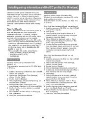
..., and click [OK]. 7. Using an application compatible with an ICC profile, highly accurate color reproduction can select the driver you want .], then click [Next]. 4. Click on the [Start] button. Click on the [Start] button. From [Settings], choose [Control Panel]. 3. Check that describes the color reproduction characteristics of the LCD monitor. English Français Deutsch Italiano Installing set-up information and the ICC profile (For Windows) Depending on the...
..., and click [OK]. 7. Using an application compatible with an ICC profile, highly accurate color reproduction can select the driver you want .], then click [Next]. 4. Click on the [Start] button. Click on the [Start] button. From [Settings], choose [Control Panel]. 3. Check that describes the color reproduction characteristics of the LCD monitor. English Français Deutsch Italiano Installing set-up information and the ICC profile (For Windows) Depending on the...
Operation Manual
Page 32
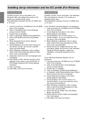
... a specific driver] and click [Next]. 8. Check [Display a list of the driver [Advanced]] and click [Next]. 3. If the "Add New Hardware Wizard" appears, repeat the installation commands beginning from :] is displayed, click on [Display]. 4. If the "Add New Hardware Wizard" has not appeared: 1. Click on the screen, and click [Finish]. From [Settings], choose [Control Panel]. 3. In [Options], check [Automatically detect Plug & Play monitors] and click on [Change...
... a specific driver] and click [Next]. 8. Check [Display a list of the driver [Advanced]] and click [Next]. 3. If the "Add New Hardware Wizard" appears, repeat the installation commands beginning from :] is displayed, click on [Display]. 4. If the "Add New Hardware Wizard" has not appeared: 1. Click on the screen, and click [Finish]. From [Settings], choose [Control Panel]. 3. In [Options], check [Automatically detect Plug & Play monitors] and click on [Change...
Operation Manual
Page 33
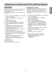
... [Update Driver]. 7. When using the ICC profile, set -up information into Windows XP, and setting the monitor's ICC profile as the file location. 7. Click on [Display]. 4. Check [Don't search. Click [OK], and close the window. - Installing the ICC profile Installing the monitor's ICC profile. (If the set as follows: - [DISPLAY MODE]: [STD] or [OFFICE] - [WHITE BALANCE]: [STD] - [GAMMA]: [0] Italiano Español English 33 Double click on the [Start] button...
... [Update Driver]. 7. When using the ICC profile, set -up information into Windows XP, and setting the monitor's ICC profile as the file location. 7. Click on [Display]. 4. Check [Don't search. Click [OK], and close the window. - Installing the ICC profile Installing the monitor's ICC profile. (If the set as follows: - [DISPLAY MODE]: [STD] or [OFFICE] - [WHITE BALANCE]: [STD] - [GAMMA]: [0] Italiano Español English 33 Double click on the [Start] button...


