

Instruction Manual
Page 3
... on fan or filter. Use duct tape to duct air outside - EN 3 3 To reduce risk of the rangehood and the cooking surface or countertop. Clean ventilating fans frequently. ALL WALL AND FLOOR OPENINGS WHERE THE RANGEHOOD IS INSTALLED MUST BE SEALED. MOBILE HOME INSTALLATION. Four wire power supply must be used and the appliance wiring must be constructed. See Electrical Requirements. You can extend either through the wall or the roof. Do not vent exhaust air into...
... on fan or filter. Use duct tape to duct air outside - EN 3 3 To reduce risk of the rangehood and the cooking surface or countertop. Clean ventilating fans frequently. ALL WALL AND FLOOR OPENINGS WHERE THE RANGEHOOD IS INSTALLED MUST BE SEALED. MOBILE HOME INSTALLATION. Four wire power supply must be used and the appliance wiring must be constructed. See Electrical Requirements. You can extend either through the wall or the roof. Do not vent exhaust air into...

Instruction Manual
Page 4
... local codes in accordance with any questions, contact the manufacturer. A UL Listed, 1/2" conduit connector must be obtained from being switched on a separate 15 amp fused circuit. When making the electrical connection, cut through wood must be provided at service panel and lock the service disconnecting means to prevent power from : National Fire Protection Association Batterymarch Park Quincy, Massachusetts 02269 This appliance should be connected directly to follow venting requirements...
... local codes in accordance with any questions, contact the manufacturer. A UL Listed, 1/2" conduit connector must be obtained from being switched on a separate 15 amp fused circuit. When making the electrical connection, cut through wood must be provided at service panel and lock the service disconnecting means to prevent power from : National Fire Protection Association Batterymarch Park Quincy, Massachusetts 02269 This appliance should be connected directly to follow venting requirements...

Instruction Manual
Page 5
... INJURY TO PERSONS, OBSERVE THE FOLLOWING: Installation Work And Electrical Wiring Must Be Done By Qualified Person(s) In Accordance With All Applicable Codes And Standards, Including Fire-Rated Construction. When cutting or drilling into wall or ceiling, do not damage electrical wiring and other materials, DO NOT use for grounding. • DO NOT ground to follow electrical requirements may result in doubt as those...
... INJURY TO PERSONS, OBSERVE THE FOLLOWING: Installation Work And Electrical Wiring Must Be Done By Qualified Person(s) In Accordance With All Applicable Codes And Standards, Including Fire-Rated Construction. When cutting or drilling into wall or ceiling, do not damage electrical wiring and other materials, DO NOT use for grounding. • DO NOT ground to follow electrical requirements may result in doubt as those...
Instruction Manual
Page 6
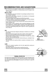
... used in conjunction with a thermal protector to direct it is in order to guarantee the entry of exhaust gas. The route of the pan only, making sure that indicated on /off button to restart the range hood. EN 6 6 INSTALLATION • The manufacturer will not be continuously monitored during use , press the on the rating plate fixed to prevent the backflow of clean air. rect use...
... used in conjunction with a thermal protector to direct it is in order to guarantee the entry of exhaust gas. The route of the pan only, making sure that indicated on /off button to restart the range hood. EN 6 6 INSTALLATION • The manufacturer will not be continuously monitored during use , press the on the rating plate fixed to prevent the backflow of clean air. rect use...
Instruction Manual
Page 7
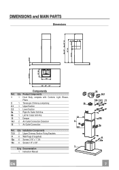
DIMENSIONS and MAIN PARTS Dimensions 2" 7/16 5" 1/8 3" 1/2 Min. 35" - Max.38" 1/8 21" 1/4 12" 1/2 2" 3/8 19" 5/16 10" 5/8 12" 24'' - 30" - 36" Components Ref. Q.ty Product Components 1 1 Hood Body, complete with: Controls, Light, Blower, Filters 2 1 Telescopic Chimney comprising: 2.1 1 Upper Section 2.2 1 Lower Section 8a 1 Right Air Outlet Grill Aria 8b 1 Left Air Outlet Grill Aria 10 1 Damper 14.1 2 Air Outlet Connection Extension 15 1 Air Outlet Connection Ref. Q.ty Installation Components 7.2.1 2 Upper Chimney Section Fixing Brackets 11 6 Wall Plugs...
DIMENSIONS and MAIN PARTS Dimensions 2" 7/16 5" 1/8 3" 1/2 Min. 35" - Max.38" 1/8 21" 1/4 12" 1/2 2" 3/8 19" 5/16 10" 5/8 12" 24'' - 30" - 36" Components Ref. Q.ty Product Components 1 1 Hood Body, complete with: Controls, Light, Blower, Filters 2 1 Telescopic Chimney comprising: 2.1 1 Upper Section 2.2 1 Lower Section 8a 1 Right Air Outlet Grill Aria 8b 1 Left Air Outlet Grill Aria 10 1 Damper 14.1 2 Air Outlet Connection Extension 15 1 Air Outlet Connection Ref. Q.ty Installation Components 7.2.1 2 Upper Chimney Section Fixing Brackets 11 6 Wall Plugs...

Instruction Manual
Page 8
... operation on the supporting wall up - INSTALLATION Wall drilling and bracket fixing ÷1/16" 7.2.1 X 11 4"9/16 4"9/16 12a 12"5/8 24" Wall marking: • Draw a vertical line on the other side. • Drill ø 5/16" holes at all the center points marked. • Insert the wall plugs 11 in the holes. • Fix the brackets using the 12a screws supplied. • Insert the two screws...
... operation on the supporting wall up - INSTALLATION Wall drilling and bracket fixing ÷1/16" 7.2.1 X 11 4"9/16 4"9/16 12a 12"5/8 24" Wall marking: • Draw a vertical line on the other side. • Drill ø 5/16" holes at all the center points marked. • Insert the wall plugs 11 in the holes. • Fix the brackets using the 12a screws supplied. • Insert the two screws...

Instruction Manual
Page 9
... dry wall, flush mounted between 2 studs. tion 15. • Make sure that the activated charcoal filters have been inserted. 15 14.1 EN 9 9 cated on the hood body mounting points. • Hook the hood body onto the screws 12a. • Fully tighten support screws 12a. • Adjust screws Vr to level the hood body. 12a Note: The Hood body should be secured to the chimney using a rigid 6" duct. • Install the damper...
... dry wall, flush mounted between 2 studs. tion 15. • Make sure that the activated charcoal filters have been inserted. 15 14.1 EN 9 9 cated on the hood body mounting points. • Hook the hood body onto the screws 12a. • Fully tighten support screws 12a. • Adjust screws Vr to level the hood body. 12a Note: The Hood body should be secured to the chimney using a rigid 6" duct. • Install the damper...

Instruction Manual
Page 10
... wall, making sure that they are well seated. • Fix the lower part laterally to the hood body using the 2 screws 12c supplied. • On the recirculation version, fit the directional grids 8a - 8b in the connection extension pieces 14.1. 7.2.1 12c 8a 12c EN 110 ELECTRICAL CONNECTION • Remove the cover from the Field Wiring Compartment with a twist-on type wire connec- tor. Ground wire Power supply cable Chimney assembly Upper exhaust chimney...
... wall, making sure that they are well seated. • Fix the lower part laterally to the hood body using the 2 screws 12c supplied. • On the recirculation version, fit the directional grids 8a - 8b in the connection extension pieces 14.1. 7.2.1 12c 8a 12c EN 110 ELECTRICAL CONNECTION • Remove the cover from the Field Wiring Compartment with a twist-on type wire connec- tor. Ground wire Power supply cable Chimney assembly Upper exhaust chimney...

Instruction Manual
Page 11
V2 Speed Medium speed, suitable for eliminating the highest cooking vapour emission, including long periods. V3 Intensive Maximum speed, used for most operating conditions given the optimum treated air flox/noise level ratio. Used to provide a continuos and silent air change in the presence of light cooking vapours. USE L S V1 V2 V3 Control board L Light Switches the lighting system on and off . EN 111 S Led Motor running led. V1 Motor Switches the extractor motor on and off at low speed.
V2 Speed Medium speed, suitable for eliminating the highest cooking vapour emission, including long periods. V3 Intensive Maximum speed, used for most operating conditions given the optimum treated air flox/noise level ratio. Used to provide a continuos and silent air change in the presence of light cooking vapours. USE L S V1 V2 V3 Control board L Light Switches the lighting system on and off . EN 111 S Led Motor running led. V1 Motor Switches the extractor motor on and off at low speed.
Instruction Manual
Page 12
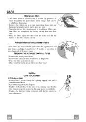
... CHARCOAL FILTER • Remove the metal grease filters. • Remove the charcoal filter as above. moved as indicated in a dishwasher. • Remove the filters one at a time, supporting them with the two screws re- CARE Metal grease filters • The filters must be washed in the picture. • Place the filter again into its seat. • Place again the metal grease filters into their place. EN 112 Lighting LIGHT REPLACEMENT 20 W halogen light. • Remove...
... CHARCOAL FILTER • Remove the metal grease filters. • Remove the charcoal filter as above. moved as indicated in a dishwasher. • Remove the filters one at a time, supporting them with the two screws re- CARE Metal grease filters • The filters must be washed in the picture. • Place the filter again into its seat. • Place again the metal grease filters into their place. EN 112 Lighting LIGHT REPLACEMENT 20 W halogen light. • Remove...

