User Guide
Page 3
... problems that cannot be solved by using the web configurator. See http://www.zyxel.com/ GS-1524/GS-1548 User's Guide 3 You should contact your vendor. It contains information on setting up your vendor, then contact a ZyXEL office for the region in which you get up and running right away. ...to help for people who want to configure the Switch using this manual, you use the web configurator to configure the Switch. • Supporting Disc Refer to the included CD for support documents. • ZyXEL Web Site Please refer to www.zyxel.com for improvement to the following address, or ...
... problems that cannot be solved by using the web configurator. See http://www.zyxel.com/ GS-1524/GS-1548 User's Guide 3 You should contact your vendor. It contains information on setting up your vendor, then contact a ZyXEL office for the region in which you get up and running right away. ...to help for people who want to configure the Switch using this manual, you use the web configurator to configure the Switch. • Supporting Disc Refer to the included CD for support documents. • ZyXEL Web Site Please refer to www.zyxel.com for improvement to the following address, or ...

User Guide
Page 5
... words". Note: Notes tell you may denote "1000000" or "1048576" and so on your device. Syntax Conventions • The GS-1524 / GS-1548 may be referred to as the "Switch", the "device", or the "system" in this User's Guide. For example, Maintenance > Log > Log Setting means you first...are shown in other things you other important information (for you to use one or more characters and then press the [ENTER] key. GS-1524/GS-1548 User's Guide 5 "Select" or "choose" means for mega may need to configure or helpful tips) or recommendations. Document Conventions Document...
... words". Note: Notes tell you may denote "1000000" or "1048576" and so on your device. Syntax Conventions • The GS-1524 / GS-1548 may be referred to as the "Switch", the "device", or the "system" in this User's Guide. For example, Maintenance > Log > Log Setting means you first...are shown in other things you other important information (for you to use one or more characters and then press the [ENTER] key. GS-1524/GS-1548 User's Guide 5 "Select" or "choose" means for mega may need to configure or helpful tips) or recommendations. Document Conventions Document...

User Guide
Page 6
The Switch Computer Notebook computer Server DSLAM Firewall Telephone Switch Router 6 GS-1524/GS-1548 User's Guide The Switch icon is not an exact representation of your device. Document Conventions Icons Used in Figures Figures in this User's Guide may use the following generic icons.
The Switch Computer Notebook computer Server DSLAM Firewall Telephone Switch Router 6 GS-1524/GS-1548 User's Guide The Switch icon is not an exact representation of your device. Document Conventions Icons Used in Figures Figures in this User's Guide may use the following generic icons.

User Guide
Page 9
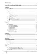
Contents Overview Contents Overview Introduction and Hardware Overview 17 Getting to Know Your Switch ...19 Hardware Installation and Connection 23 Hardware Overview ...27 Basic & Advanced Settings 33 The Web Configurator ...35 System ...43 Port Settings ...49 System and Port ... ...93 Management and Troubleshooting 95 Event Logging ...97 SNMP ...105 RMON-Lite ...121 Dynamic ARP ...137 Troubleshooting ...141 Product Specifications ...145 Appendices and Index ...151 GS-1524/GS-1548 User's Guide 9
Contents Overview Contents Overview Introduction and Hardware Overview 17 Getting to Know Your Switch ...19 Hardware Installation and Connection 23 Hardware Overview ...27 Basic & Advanced Settings 33 The Web Configurator ...35 System ...43 Port Settings ...49 System and Port ... ...93 Management and Troubleshooting 95 Event Logging ...97 SNMP ...105 RMON-Lite ...121 Dynamic ARP ...137 Troubleshooting ...141 Product Specifications ...145 Appendices and Index ...151 GS-1524/GS-1548 User's Guide 9

User Guide
Page 11
... Overview 17 Chapter 1 Getting to Know Your Switch 19 1.1 Introduction ...19 1.1.1 Backbone Application 19 1.1.2 Bridging Example ...20 1.1.3 High Performance Switching Example 21 1.1.4 IEEE 802.1Q VLAN Application ...Switch on a Rack 24 2.2.1 Rack-mounted Installation Requirements 24 2.2.2 Attaching the Mounting Brackets to the Switch 24 2.2.3 Mounting the Switch on a Rack 25 Chapter 3 Hardware Overview...27 3.1 Front Panel ...27 3.1.1 Ethernet Ports ...28 3.1.2 Mini-GBIC Slots ...28 3.2 The RESET Button ...30 3.3 LEDs ...30 3.4 Rear Panel ...31 3.4.1 Power Connector ...32 GS-1524/GS...
... Overview 17 Chapter 1 Getting to Know Your Switch 19 1.1 Introduction ...19 1.1.1 Backbone Application 19 1.1.2 Bridging Example ...20 1.1.3 High Performance Switching Example 21 1.1.4 IEEE 802.1Q VLAN Application ...Switch on a Rack 24 2.2.1 Rack-mounted Installation Requirements 24 2.2.2 Attaching the Mounting Brackets to the Switch 24 2.2.3 Mounting the Switch on a Rack 25 Chapter 3 Hardware Overview...27 3.1 Front Panel ...27 3.1.1 Ethernet Ports ...28 3.1.2 Mini-GBIC Slots ...28 3.2 The RESET Button ...30 3.3 LEDs ...30 3.4 Rear Panel ...31 3.4.1 Power Connector ...32 GS-1524/GS...
User Guide
Page 12
... 4.2 System Login ...35 4.3 The Status Screen ...36 4.3.1 The LED Panel ...37 4.3.2 The Navigation Panel 37 4.3.3 Change Your Password 39 4.4 Saving Your Configuration 39 4.5 Switch Lockout ...40 4.6 Resetting the Switch ...40 4.7 Logging Out of the Web Configurator 41 4.8 Help ...41 Chapter 5 System ...43 5.1 System Screen ...43 5.1.1 Configure IP Address 44 5.1.2 Layer 2 (L2) Table... ...53 7.3 Port Statistics ...54 Chapter 8 VLAN ...57 8.1 Introduction to IEEE 802.1Q Tagged VLANs 57 8.1.1 Forwarding Tagged and Untagged Frames 57 8.2 Static VLAN ...58 12 GS-1524/GS-1548 User's Guide
... 4.2 System Login ...35 4.3 The Status Screen ...36 4.3.1 The LED Panel ...37 4.3.2 The Navigation Panel 37 4.3.3 Change Your Password 39 4.4 Saving Your Configuration 39 4.5 Switch Lockout ...40 4.6 Resetting the Switch ...40 4.7 Logging Out of the Web Configurator 41 4.8 Help ...41 Chapter 5 System ...43 5.1 System Screen ...43 5.1.1 Configure IP Address 44 5.1.2 Layer 2 (L2) Table... ...53 7.3 Port Statistics ...54 Chapter 8 VLAN ...57 8.1 Introduction to IEEE 802.1Q Tagged VLANs 57 8.1.1 Forwarding Tagged and Untagged Frames 57 8.2 Static VLAN ...58 12 GS-1524/GS-1548 User's Guide

User Guide
Page 15
... 138 20.3 Viewing ARP Table Entries 139 20.4 Adding ARP Table Entries 140 Chapter 21 Troubleshooting...141 21.1 Power, Hardware Connections, and LEDs 141 21.2 Switch Access and Login 142 Chapter 22 Product Specifications ...145 22.1 General Switch Specifications 145 Part IV: Appendices and Index 151 GS-1524/GS-1548 User's Guide 15
... 138 20.3 Viewing ARP Table Entries 139 20.4 Adding ARP Table Entries 140 Chapter 21 Troubleshooting...141 21.1 Power, Hardware Connections, and LEDs 141 21.2 Switch Access and Login 142 Chapter 22 Product Specifications ...145 22.1 General Switch Specifications 145 Part IV: Appendices and Index 151 GS-1524/GS-1548 User's Guide 15

User Guide
Page 17
PART I Introduction and Hardware Overview Getting to Know Your Switch (19) Hardware Installation and Connection (23) Hardware Overview (27) 17
PART I Introduction and Hardware Overview Getting to Know Your Switch (19) Hardware Installation and Connection (23) Hardware Overview (27) 17

User Guide
Page 19
GS-1524/GS-1548 User's Guide 19 CHAPTER 1 Getting to the Switch. See Chapter 22 on the Switch. 1.1.1 Backbone Application The Switch is easy. With its built-in the near future. You can be expected in web configurator, managing and configuring the Switch is an ideal solution for small networks where rapid... for a group of heavy traffic users. The Switch features dual-personality ports, each of which consists of software features available on page 145 for a full list of one 1000BASE-T RJ-45 port and one time. • The GS-1524 has 20 1000BASE-T RJ-45 ports, and four...
GS-1524/GS-1548 User's Guide 19 CHAPTER 1 Getting to the Switch. See Chapter 22 on the Switch. 1.1.1 Backbone Application The Switch is easy. With its built-in the near future. You can be expected in web configurator, managing and configuring the Switch is an ideal solution for small networks where rapid... for a group of heavy traffic users. The Switch features dual-personality ports, each of which consists of software features available on page 145 for a full list of one 1000BASE-T RJ-45 port and one time. • The GS-1524 has 20 1000BASE-T RJ-45 ports, and four...

User Guide
Page 20
... Moreover, the Switch eases supervision and maintenance by using a Gigabit Ethernet/mini-GBIC port on the server. You can share high-speed applications on the Switch. It can connect to high-speed department servers via the Switch. Figure 2 Bridging Application 20 GS-1524/GS-1548 User's... Guide To expand the network, simply add more networking devices such as switches, routers, computers, print servers etc.
... Moreover, the Switch eases supervision and maintenance by using a Gigabit Ethernet/mini-GBIC port on the server. You can share high-speed applications on the Switch. It can connect to high-speed department servers via the Switch. Figure 2 Bridging Application 20 GS-1524/GS-1548 User's... Guide To expand the network, simply add more networking devices such as switches, routers, computers, print servers etc.

User Guide
Page 21
... connect these two networks. With VLAN, a station cannot directly talk to one group. GS-1524/GS-1548 User's Guide 21 A station can provide the same bandwidth as all existing Ethernet cables and adapter cards, restructuring your network and complex maintenance. The Switch can belong to more information on VLANs, refer to Chapter 8 on a logical...
... connect these two networks. With VLAN, a station cannot directly talk to one group. GS-1524/GS-1548 User's Guide 21 A station can provide the same bandwidth as all existing Ethernet cables and adapter cards, restructuring your network and complex maintenance. The Switch can belong to more information on VLANs, refer to Chapter 8 on a logical...

User Guide
Page 22
Figure 4 Shared Server Using VLAN Example 22 GS-1524/GS-1548 User's Guide Ports on the Switch can be part of VLAN 1. In the following figure only ports that need access to the server need to be used by all ports in the same VLAN as a server can belong to Know Your Switch Shared resources such as the server. Chapter 1 Getting to other VLAN groups too.
Figure 4 Shared Server Using VLAN Example 22 GS-1524/GS-1548 User's Guide Ports on the Switch can be part of VLAN 1. In the following figure only ports that need access to the server need to be used by all ports in the same VLAN as a server can belong to Know Your Switch Shared resources such as the server. Chapter 1 Getting to other VLAN groups too.

User Guide
Page 23
...enough to support the weight of the Switch and the connected cables. Make sure there is a power outlet nearby. 3 Make sure there is clean and dry. 2 Set the Switch on the bottom of the Switch. Figure 5 Attaching Rubber Feet GS-1524/GS-1548 User's Guide 23 CHAPTER 2 ...Hardware Installation and Connection This chapter shows you how to install and connect the Switch. 2.1 Freestanding Installation 1 Make sure the Switch is enough clearance around the Switch to allow...
...enough to support the weight of the Switch and the connected cables. Make sure there is a power outlet nearby. 3 Make sure there is clean and dry. 2 Set the Switch on the bottom of the Switch. Figure 5 Attaching Rubber Feet GS-1524/GS-1548 User's Guide 23 CHAPTER 2 ...Hardware Installation and Connection This chapter shows you how to install and connect the Switch. 2.1 Freestanding Installation 1 Make sure the Switch is enough clearance around the Switch to allow...

User Guide
Page 24
...ventilation, allow at least 4 inches (10 cm) of clearance at the front and 3.4 inches (8 cm) at the back of the Switch, lining up the four screw holes on the bracket with the screw holes on a Rack This section lists the rack mounting requirements and... the rack securely before installing the unit. 2.2.2 Attaching the Mounting Brackets to the Switch 1 Position a mounting bracket on one side of the Switch. Leave space between devices when stacking. Figure 6 Attaching the Mounting Brackets 24 GS-1524/GS-1548 User's Guide Chapter 2 Hardware Installation and Connection Note: Do NOT block the...
...ventilation, allow at least 4 inches (10 cm) of clearance at the front and 3.4 inches (8 cm) at the back of the Switch, lining up the four screw holes on the bracket with the screw holes on a Rack This section lists the rack mounting requirements and... the rack securely before installing the unit. 2.2.2 Attaching the Mounting Brackets to the Switch 1 Position a mounting bracket on one side of the Switch. Leave space between devices when stacking. Figure 6 Attaching the Mounting Brackets 24 GS-1524/GS-1548 User's Guide Chapter 2 Hardware Installation and Connection Note: Do NOT block the...

User Guide
Page 25
GS-1524/GS-1548 User's Guide 25 Figure 7 Mounting the Switch on a Rack 2 Using a #2 Philips screwdriver, install the M5 flat head screws through the mounting bracket holes into the rack. 3 Repeat steps 1 and 2 to the Switch) on one side of the rack, lining up the two screw holes on the bracket with the screw holes on... the side of the rack. Proceed to the next section. 2.2.3 Mounting the Switch on a Rack 1 Position a mounting bracket (that is already attached to attach the second mounting bracket on the other side of the...
GS-1524/GS-1548 User's Guide 25 Figure 7 Mounting the Switch on a Rack 2 Using a #2 Philips screwdriver, install the M5 flat head screws through the mounting bracket holes into the rack. 3 Repeat steps 1 and 2 to the Switch) on one side of the rack, lining up the two screw holes on the bracket with the screw holes on... the side of the rack. Proceed to the next section. 2.2.3 Mounting the Switch on a Rack 1 Position a mounting bracket (that is already attached to attach the second mounting bracket on the other side of the...

User Guide
Page 27
Figure 8 GS-1524 Front Panel LEDs RJ-45 Gigabit Ethernet Mini-GBIC Figure 9 GS-1548 Front Panel LEDs RJ-45 Gigabit Ethernet GS-1524/GS-1548 User's Guide Mini-GBIC 27 CHAPTER 3 Hardware Overview This chapter describes the front panel and rear panel of the Switch and shows you how to make the hardware connections. 3.1 Front Panel The figures below show the front panel of the Switch.
Figure 8 GS-1524 Front Panel LEDs RJ-45 Gigabit Ethernet Mini-GBIC Figure 9 GS-1548 Front Panel LEDs RJ-45 Gigabit Ethernet GS-1524/GS-1548 User's Guide Mini-GBIC 27 CHAPTER 3 Hardware Overview This chapter describes the front panel and rear panel of the Switch and shows you how to make the hardware connections. 3.1 Front Panel The figures below show the front panel of the Switch.

User Guide
Page 28
...automatically works with transceivers. Ports Mini-GBIC Slots Use mini-GBIC transceivers in these Gigabit Ethernet ports to backbone Ethernet switches. 3.1.1 Ethernet Ports The GS-1524 has 24 auto-negotiating, auto-crossover RJ-45 Gigabit Ethernet ports. A transceiver is a single unit that comply ... CONNECTO R DESCRIPTION RJ-45 Gigabit Connect these slots for details. 28 GS-1524/GS-1548 User's Guide An auto-negotiating port can be half duplex (at 100 Mbps) or full duplex. The Switch does not come with a straightthrough or crossover Ethernet cable. 3.1.1.1 Default Ethernet...
...automatically works with transceivers. Ports Mini-GBIC Slots Use mini-GBIC transceivers in these Gigabit Ethernet ports to backbone Ethernet switches. 3.1.1 Ethernet Ports The GS-1524 has 24 auto-negotiating, auto-crossover RJ-45 Gigabit Ethernet ports. A transceiver is a single unit that comply ... CONNECTO R DESCRIPTION RJ-45 Gigabit Connect these slots for details. 28 GS-1524/GS-1548 User's Guide An auto-negotiating port can be half duplex (at 100 Mbps) or full duplex. The Switch does not come with a straightthrough or crossover Ethernet cable. 3.1.1.1 Default Ethernet...

User Guide
Page 29
Chapter 3 Hardware Overview You can use different transceivers to connect to Ethernet switches with the exposed section of PCB board facing down. Check the LEDs to verify that it clicks into the slot ... The Switch automatically detects the installed transceiver. You can change transceivers while the Switch is functioning properly. Figure 11 Installed Transceiver 3.1.2.2 Transceiver Removal Use the following steps to remove a mini GBIC transceiver (SFP module). Figure 10 Transceiver Installation Example 2 Press the transceiver firmly until it is operating. GS-1524/GS-1548 User...
Chapter 3 Hardware Overview You can use different transceivers to connect to Ethernet switches with the exposed section of PCB board facing down. Check the LEDs to verify that it clicks into the slot ... The Switch automatically detects the installed transceiver. You can change transceivers while the Switch is functioning properly. Figure 11 Installed Transceiver 3.1.2.2 Transceiver Removal Use the following steps to remove a mini GBIC transceiver (SFP module). Figure 10 Transceiver Installation Example 2 Press the transceiver firmly until it is operating. GS-1524/GS-1548 User...

User Guide
Page 30
...Transceiver's Latch Example 2 Pull the transceiver out of the GS-1524. Table 2 LEDs LED STATUS PWR Green On Off SYS Green On Off DESCRIPTION The system is malfunctioning. 30 GS-1524/GS-1548 User's Guide Press the RESET button for the Switch to 2 minutes for one second and release. The ...RESET button is on the front panel of the GS-1548 or on . Figure 13 Transceiver Removal Example 3.1.3 ...
...Transceiver's Latch Example 2 Pull the transceiver out of the GS-1524. Table 2 LEDs LED STATUS PWR Green On Off SYS Green On Off DESCRIPTION The system is malfunctioning. 30 GS-1524/GS-1548 User's Guide Press the RESET button for the Switch to 2 minutes for one second and release. The ...RESET button is on the front panel of the GS-1548 or on . Figure 13 Transceiver Removal Example 3.1.3 ...

User Guide
Page 31
... link to an Ethernet network is receiving or transmitting data. Off The link to this port. The GS-1524's rear panel also contains the RESET button. Figure 14 GS-1524 Rear Panel Figure 15 GS-1548 Rear Panel 3.3.1 Power Connector Make sure you are occurring. GBIC Slots LNK Green On The port...is connected to an Ethernet network is down . 3.3 Rear Panel The following figures show the rear panels of the AC power input model Switch. GS-1524/GS-1548 User's Guide 31 Amber On The link to a 10/1000 Mbps Ethernet network is up . Off The port is up . Gigabit Ethernet...
... link to an Ethernet network is receiving or transmitting data. Off The link to this port. The GS-1524's rear panel also contains the RESET button. Figure 14 GS-1524 Rear Panel Figure 15 GS-1548 Rear Panel 3.3.1 Power Connector Make sure you are occurring. GBIC Slots LNK Green On The port...is connected to an Ethernet network is down . 3.3 Rear Panel The following figures show the rear panels of the AC power input model Switch. GS-1524/GS-1548 User's Guide 31 Amber On The link to a 10/1000 Mbps Ethernet network is up . Off The port is up . Gigabit Ethernet...