
Owners Manual
Page 7
... ...Meter Instruments ...Tachometer: ...LCD (Speedometer, Clock, Odometer, Trip Meters, Fuel Level Gauge):...Warning/Indicator Lights: ...Key ...Ignition Switch/Steering Lock ...Right Handlebar Switches...Engine Stop Switch: ...Starter Button: ...Left Handlebar Switches ...Dimmer Switch: ...7 11 12 15 28 31 31 31 Turn Signal Switch:...Horn Button: ...Passing Button: ...Hazard Switch: ...Brake/Clutch Lever Adjusters...Fuel Tank Cap ...Fuel Tank ...Fuel Requirement: ...Stand...Seat Lock ...Helmet Holding Hooks ...Tool Kit/U-Shaped lock Compartment ...Rear View Mirror ...Windshield...BREAK-IN...
... ...Meter Instruments ...Tachometer: ...LCD (Speedometer, Clock, Odometer, Trip Meters, Fuel Level Gauge):...Warning/Indicator Lights: ...Key ...Ignition Switch/Steering Lock ...Right Handlebar Switches...Engine Stop Switch: ...Starter Button: ...Left Handlebar Switches ...Dimmer Switch: ...7 11 12 15 28 31 31 31 Turn Signal Switch:...Horn Button: ...Passing Button: ...Hazard Switch: ...Brake/Clutch Lever Adjusters...Fuel Tank Cap ...Fuel Tank ...Fuel Requirement: ...Stand...Seat Lock ...Helmet Holding Hooks ...Tool Kit/U-Shaped lock Compartment ...Rear View Mirror ...Windshield...BREAK-IN...

Owners Manual
Page 8
... Periodic Maintenance Chart...Engine Oil ...Cooling System ...Spark Plugs...Evaporative Emission Control System (California model only) ...Valve Clearance ...Kawasaki Clean Air System ...Air Cleaner ... 69 70 72 72 73 75 77 77 78 80 82 86 100 106 113 114 115 116 117 Throttle Control System ...Engine Vacuum Synchronization ...Idle Speed ...Clutch ...Drive Chain ...Brakes ...Brake Light Switches...Front Fork...Rear Shock Absorber...Wheels ...Battery...Headlight Beam...Fuses ...General Lubrication...Cleaning Your Motorcycle ...Bolt and Nut Tightening...STORAGE ...TROUBLESHOOTING GUIDE...OWNER...
... Periodic Maintenance Chart...Engine Oil ...Cooling System ...Spark Plugs...Evaporative Emission Control System (California model only) ...Valve Clearance ...Kawasaki Clean Air System ...Air Cleaner ... 69 70 72 72 73 75 77 77 78 80 82 86 100 106 113 114 115 116 117 Throttle Control System ...Engine Vacuum Synchronization ...Idle Speed ...Clutch ...Drive Chain ...Brakes ...Brake Light Switches...Front Fork...Rear Shock Absorber...Wheels ...Battery...Headlight Beam...Fuses ...General Lubrication...Cleaning Your Motorcycle ...Bolt and Nut Tightening...STORAGE ...TROUBLESHOOTING GUIDE...OWNER...

Owners Manual
Page 14
12 LOCATION OF PARTS LOCATION OF PARTS 1. 2. 3. 4. Clutch Lever Left Handlebar Switches Meter Instruments Brake Fluid Reservoir (Front) 5. 6. 7. 8. Right Handlebar Switches Front Brake Lever Throttle Grip Ignition Switch/Steering Lock
12 LOCATION OF PARTS LOCATION OF PARTS 1. 2. 3. 4. Clutch Lever Left Handlebar Switches Meter Instruments Brake Fluid Reservoir (Front) 5. 6. 7. 8. Right Handlebar Switches Front Brake Lever Throttle Grip Ignition Switch/Steering Lock

Owners Manual
Page 16
Oil Level Gauge 35. Fuel Tank 30. Fuel Tank Cap 31. Muffler 32. Coolant Reserve Tank Rear Brake Light Switch 33. Idle Adjusting Screw 38. 14 LOCATION OF PARTS 26. Rear Brake Pedal 34. Brake Fluid Reservoir (Rear) 29. Rebound Damping Force Adjuster 37. License Plate Light 27. Rear Shock Absorber 36. Tail/Brake Light 28.
Oil Level Gauge 35. Fuel Tank 30. Fuel Tank Cap 31. Muffler 32. Coolant Reserve Tank Rear Brake Light Switch 33. Idle Adjusting Screw 38. 14 LOCATION OF PARTS 26. Rear Brake Pedal 34. Brake Fluid Reservoir (Rear) 29. Rebound Damping Force Adjuster 37. License Plate Light 27. Rear Shock Absorber 36. Tail/Brake Light 28.

Owners Manual
Page 32
..., windshields, backrests, and other aspect of such accessories will increase the mass of their weight, but can only warn that you have not adversely affected any lighting components, road clearance, banking capability (i.e., lean angle), control operation, wheel travel, front fork movement, or any trailer or other vehicle. Maximum Load Weight of the motorcycle. Do not install accessories or carry baggage that Kawasaki cannot...
..., windshields, backrests, and other aspect of such accessories will increase the mass of their weight, but can only warn that you have not adversely affected any lighting components, road clearance, banking capability (i.e., lean angle), control operation, wheel travel, front fork movement, or any trailer or other vehicle. Maximum Load Weight of the motorcycle. Do not install accessories or carry baggage that Kawasaki cannot...

Owners Manual
Page 38
..." button. The hour • Push display stops flashing and the minute display starts flashing. Pushing and holding the button advance the hour or minute continuously. żThe clock works normally from the back-up power while the ignition switch is turned off. żWhen the battery is connected. Push the "MODE" button. Push the "MODE" button to...
..." button. The hour • Push display stops flashing and the minute display starts flashing. Pushing and holding the button advance the hour or minute continuously. żThe clock works normally from the back-up power while the ignition switch is turned off. żWhen the battery is connected. Push the "MODE" button. Push the "MODE" button to...

Owners Manual
Page 40
38 GENERAL INFORMATION żThe data is maintained by the back NOTE -up power if the ignition key is turned off. żWhen the trip meter is reset while the vehicle is stopped, it starts counting as soon as the vehicle starts moving. żWhen the trip meter reaches 999.9 (TRIP A) or 9999.9 (TRIP B) while running, the meters reset to 0.0 and continues counting. żWhen the battery is disconnected, the meter display resets to 0.0.
38 GENERAL INFORMATION żThe data is maintained by the back NOTE -up power if the ignition key is turned off. żWhen the trip meter is reset while the vehicle is stopped, it starts counting as soon as the vehicle starts moving. żWhen the trip meter reaches 999.9 (TRIP A) or 9999.9 (TRIP B) while running, the meters reset to 0.0 and continues counting. żWhen the battery is disconnected, the meter display resets to 0.0.

Owners Manual
Page 44
... off . Steering locked. Ignition Switch/Steering Lock B. ON position C. Steering locked. P(Park) A. 42 GENERAL INFORMATION Ignition Switch/Steering Lock This is released after turning the ignition key to "ON". All electrical circuits off . Engine off . LOCK position E. One headlight goes on and turn signals can be removed from the switch when it is in the OFF, LOCK, or P (Park) position. To avoid battery discharge, always start the engine immediately after starting the engine. All electrical equipment can be used . OFF ON LOCK Engine off...
... off . Steering locked. Ignition Switch/Steering Lock B. ON position C. Steering locked. P(Park) A. 42 GENERAL INFORMATION Ignition Switch/Steering Lock This is released after turning the ignition key to "ON". All electrical circuits off . Engine off . LOCK position E. One headlight goes on and turn signals can be removed from the switch when it is in the OFF, LOCK, or P (Park) position. To avoid battery discharge, always start the engine immediately after starting the engine. All electrical equipment can be used . OFF ON LOCK Engine off...

Owners Manual
Page 49
NOTE To close the cap, or the cap cannot be removed by turning it down into the fuel tank cap and turn the key to the original position. Insert the ignition key into place with the key inserted. GENERAL INFORMATION 47 Fuel Tank Cap To open the fuel tank cap, pull up the key hole cover. A. Adjuster B. Mark żThe fuel tank cap cannot be closed NOTE without the key inserted, and the key cannot be removed unless the cap is locked properly. żDo not push on the key to close the cap, push it to the left to the right. The key can be locked.
NOTE To close the cap, or the cap cannot be removed by turning it down into the fuel tank cap and turn the key to the original position. Insert the ignition key into place with the key inserted. GENERAL INFORMATION 47 Fuel Tank Cap To open the fuel tank cap, pull up the key hole cover. A. Adjuster B. Mark żThe fuel tank cap cannot be closed NOTE without the key inserted, and the key cannot be removed unless the cap is locked properly. żDo not push on the key to close the cap, push it to the left to the right. The key can be locked.

Owners Manual
Page 71
... still. WARNING When shifting down to a lower gear, do not shift at such a high speed that the engine r/min (rpm) jumps excessively. Not only can this cause engine damage, but the rear wheel may skid and cause an accident. For smooth riding, each gear. The transmission will shift only into the next higher or lower gear. Downshifting should cover the proper rate of speed shown in the clutch lever...
... still. WARNING When shifting down to a lower gear, do not shift at such a high speed that the engine r/min (rpm) jumps excessively. Not only can this cause engine damage, but the rear wheel may skid and cause an accident. For smooth riding, each gear. The transmission will shift only into the next higher or lower gear. Downshifting should cover the proper rate of speed shown in the clutch lever...

Owners Manual
Page 80
... engine from too rapid acceleration or deceleration. Do not downshift at the proper rate of control. Avoiding unnecessary weaving is important to the safety of these checks will be used judiciously to avoid skidding the rear wheel from overrevving. The time required is necessary as in wet conditions or on the front and rear brakes. When riding in passing, shift to a lower gear...
... engine from too rapid acceleration or deceleration. Do not downshift at the proper rate of control. Avoiding unnecessary weaving is important to the safety of these checks will be used judiciously to avoid skidding the rear wheel from overrevving. The time required is necessary as in wet conditions or on the front and rear brakes. When riding in passing, shift to a lower gear...

Owners Manual
Page 81
.... Nuts, bolts, fasteners .. Drive chain ...Slack 25 ∼ 35 mm (1.0 ∼ 1.4 in .) left. Check that steering and suspension components, axles, and all controls are properly tightened or fastened. No brake fluid leakage. No binding of control cables. Tires ...Air pressure (when cold): Front Rear Up to 180 kg (397 lb) Load Up to perform these checks every day before you ride may result in tank, no leaks. Brakes ...Brake pad wear...
.... Nuts, bolts, fasteners .. Drive chain ...Slack 25 ∼ 35 mm (1.0 ∼ 1.4 in .) left. Check that steering and suspension components, axles, and all controls are properly tightened or fastened. No brake fluid leakage. No binding of control cables. Tires ...Air pressure (when cold): Front Rear Up to 180 kg (397 lb) Load Up to perform these checks every day before you ride may result in tank, no leaks. Brakes ...Brake pad wear...

Owners Manual
Page 82
... no play. Electrical equipment ...All lights (Headlight, Tail/Brake Lights, Turn Signal Lights, Warning/Indicator Lights) and horn work. Steering: Looseness in the steering can cause loss of the brakes, especially during high speed operation. 80 SAFE OPERATION Throttle ...Throttle grip play 2 ∼ 3 mm (0.08 ∼ 0.12 in.). Clutch ...Clutch lever play 2 ∼ 3 mm (0.08 ∼ 0.12 in.). Coolant ...No coolant leakage. Engine stop switch ...Stops engine. Additional Considerations for High Speed Operation Brakes: The importance of control. Check...
... no play. Electrical equipment ...All lights (Headlight, Tail/Brake Lights, Turn Signal Lights, Warning/Indicator Lights) and horn work. Steering: Looseness in the steering can cause loss of the brakes, especially during high speed operation. 80 SAFE OPERATION Throttle ...Throttle grip play 2 ∼ 3 mm (0.08 ∼ 0.12 in.). Clutch ...Clutch lever play 2 ∼ 3 mm (0.08 ∼ 0.12 in.). Coolant ...No coolant leakage. Engine stop switch ...Stops engine. Additional Considerations for High Speed Operation Brakes: The importance of control. Check...

Owners Manual
Page 97
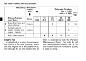
MAINTENANCE AND ADJUSTMENT 95 Frequency Whichever comes first *Odometer Reading km × 1 000 (mile × 1 000) See Page Operation (Chassis Items) Brake operation (effectiveness, play, drag) inspect Brake light switch operation inspect Suspensions: Every 1 (0.6) 6 (3.75) 12 (7.5) 18 (11.25) 24 30 36 (15) (18.75) (22.5) year • • • • • • • • • • • • • • 138 139
MAINTENANCE AND ADJUSTMENT 95 Frequency Whichever comes first *Odometer Reading km × 1 000 (mile × 1 000) See Page Operation (Chassis Items) Brake operation (effectiveness, play, drag) inspect Brake light switch operation inspect Suspensions: Every 1 (0.6) 6 (3.75) 12 (7.5) 18 (11.25) 24 30 36 (15) (18.75) (22.5) year • • • • • • • • • • • • • • 138 139
Owners Manual
Page 102
... long. replace Spark plug - Not only do dirt and metal particles collect in accordance with the Periodic Maintenance Chart. 100 MAINTENANCE AND ADJUSTMENT Frequency Whichever comes first *Odometer Reading km × 1 000 (mile × 1 000) See Page 12 (7.5) 24 (15) 36 (22.5) 48 (30) Change/Replacement Items K Every 1 (0.6) Brake fluid (front and 2 years rear) - replace Engine Oil In order for the engine, transmission, and clutch to function...
... long. replace Spark plug - Not only do dirt and metal particles collect in accordance with the Periodic Maintenance Chart. 100 MAINTENANCE AND ADJUSTMENT Frequency Whichever comes first *Odometer Reading km × 1 000 (mile × 1 000) See Page 12 (7.5) 24 (15) 36 (22.5) 48 (30) Change/Replacement Items K Every 1 (0.6) Brake fluid (front and 2 years rear) - replace Engine Oil In order for the engine, transmission, and clutch to function...

Owners Manual
Page 105
... authorities for approved disposal methods or possible recycling. Drain Plug NOTE the oil completely drain with a new one. żIf a torque wrench or required Kawasaki special tool is a toxic substance. the oil filter cartridge and re• Remove place it . A. Remove the engine oil drain plug. • • • WARNING Motor oil is not available, this item should be serviced by a Kawasaki dealer.
... authorities for approved disposal methods or possible recycling. Drain Plug NOTE the oil completely drain with a new one. żIf a torque wrench or required Kawasaki special tool is a toxic substance. the oil filter cartridge and re• Remove place it . A. Remove the engine oil drain plug. • • • WARNING Motor oil is not available, this item should be serviced by a Kawasaki dealer.

Owners Manual
Page 133
..., and damaged teeth. Measure the length of 20 links on the chain. A. Weight Since the chain may wear unevenly, take measurements at several places. Also inspect the sprockets for damaged rollers, and the length exceeds the service limit, • If the chain should not be replaced. • loose pins and links. the rear wheel to pin center of the 21st pin.
..., and damaged teeth. Measure the length of 20 links on the chain. A. Weight Since the chain may wear unevenly, take measurements at several places. Also inspect the sprockets for damaged rollers, and the length exceeds the service limit, • If the chain should not be replaced. • loose pins and links. the rear wheel to pin center of the 21st pin.

Owners Manual
Page 140
138 MAINTENANCE AND ADJUSTMENT Brake Light Switches When either the front or rear brake is applied, the brake light goes on. The front brake light switch requires no adjustment, but the rear brake light switch should be adjusted in accordance with the Periodic Maintenance Chart.
138 MAINTENANCE AND ADJUSTMENT Brake Light Switches When either the front or rear brake is applied, the brake light goes on. The front brake light switch requires no adjustment, but the rear brake light switch should be adjusted in accordance with the Periodic Maintenance Chart.

Owners Manual
Page 141
The brake light should go on when the front brake is applied. MAINTENANCE AND ADJUSTMENT 139 Inspection Turn the ignition key to inspect the front brake light switch. • • • it does not, ask your authorized Kawasaki dealer to "ON". Connector A. Pedal Travel The brake light should go on after the proper pedal travel. If it does not, adjust the rear brake • If light switch. Brake Pedal...
The brake light should go on when the front brake is applied. MAINTENANCE AND ADJUSTMENT 139 Inspection Turn the ignition key to inspect the front brake light switch. • • • it does not, ask your authorized Kawasaki dealer to "ON". Connector A. Pedal Travel The brake light should go on after the proper pedal travel. If it does not, adjust the rear brake • If light switch. Brake Pedal...

Owners Manual
Page 142
... Inspection Holding the brake lever, pump the front fork up or down by turning the switch body. Visually inspect the front fork for inspection of the inner tube. • • A. Rear Brake Light Switch Adjusting Nut Lights sooner Lights later • Connect the connector. 140 MAINTENANCE AND ADJUSTMENT adjust the rear brake light switch, • To move the switch up and down by several times for oil leakage, scoring...
... Inspection Holding the brake lever, pump the front fork up or down by turning the switch body. Visually inspect the front fork for inspection of the inner tube. • • A. Rear Brake Light Switch Adjusting Nut Lights sooner Lights later • Connect the connector. 140 MAINTENANCE AND ADJUSTMENT adjust the rear brake light switch, • To move the switch up and down by several times for oil leakage, scoring...
