

Owners Manual
Page 6
... on their own work should, of Kawasaki's advanced engineering, exhaustive testing, and continuous striving for superior reliability, safety and performance. Kawasaki strongly recommends that all operators of this Owner's Manual carefully before riding so that you can refer to attain awareness of a new Kawasaki Motorcycle. For those who plan to ride a motorcycle safely. The Service Manual contains detailed disassembly and maintenance information. Keep this...
... on their own work should, of Kawasaki's advanced engineering, exhaustive testing, and continuous striving for superior reliability, safety and performance. Kawasaki strongly recommends that all operators of this Owner's Manual carefully before riding so that you can refer to attain awareness of a new Kawasaki Motorcycle. For those who plan to ride a motorcycle safely. The Service Manual contains detailed disassembly and maintenance information. Keep this...
Owners Manual
Page 8
... ...GENERAL INFORMATION ...Meter Instruments ...Speedometer: ...Digital Display ...Fuel Gauge: ...RESET Button/MODE button: ...Warning/Indicator Lights: ...Keys ...Ignition Switch ...Right Handlebar Switches...Engine Stop Switch: ...Starter Button: ...Left Handlebar Switches ...Dimmer Switch: ...Turn Signal Switch:...8 12 13 16 19 22 22 23 23 26 26 26 28 29 31 31 31 32 32 32 Horn Button: ...Brake Lever Adjusters...Fuel Tank Cap ...Fuel Tank ...Side Stand ...Seat...Tool Kit Case ...Helmet-Hook ...Steering Lock ...Electric Accessory Connectors ...BREAK-IN ...HOW...
... ...GENERAL INFORMATION ...Meter Instruments ...Speedometer: ...Digital Display ...Fuel Gauge: ...RESET Button/MODE button: ...Warning/Indicator Lights: ...Keys ...Ignition Switch ...Right Handlebar Switches...Engine Stop Switch: ...Starter Button: ...Left Handlebar Switches ...Dimmer Switch: ...Turn Signal Switch:...8 12 13 16 19 22 22 23 23 26 26 26 28 29 31 31 31 32 32 32 Horn Button: ...Brake Lever Adjusters...Fuel Tank Cap ...Fuel Tank ...Side Stand ...Seat...Tool Kit Case ...Helmet-Hook ...Steering Lock ...Electric Accessory Connectors ...BREAK-IN ...HOW...

Owners Manual
Page 9
... Periodic Maintenance Chart...Engine Oil ...Cooling System ...Drive Belt...Spark Plugs...Evaporative Emission Control System (California model only) ...Valve Clearance ...Kawasaki Clean Air System ...Air Cleaner ...Throttle Control System ...Idle Speed ... 62 64 66 66 69 72 74 79 89 96 102 103 104 105 106 107 109 111 Clutch ...Brakes ...Brake Light Switches...Rear Shock Absorber...Wheels ...Battery...Headlight Beam...Fuses ...General Lubrication...Cleaning Your Motorcycle ...Bolt and Nut Tightening...STORAGE ...TROUBLESHOOTING GUIDE...YOUR WARRANTY/OWNER SATISFACTION ...Reporting Safety...
... Periodic Maintenance Chart...Engine Oil ...Cooling System ...Drive Belt...Spark Plugs...Evaporative Emission Control System (California model only) ...Valve Clearance ...Kawasaki Clean Air System ...Air Cleaner ...Throttle Control System ...Idle Speed ... 62 64 66 66 69 72 74 79 89 96 102 103 104 105 106 107 109 111 Clutch ...Brakes ...Brake Light Switches...Rear Shock Absorber...Wheels ...Battery...Headlight Beam...Fuses ...General Lubrication...Cleaning Your Motorcycle ...Bolt and Nut Tightening...STORAGE ...TROUBLESHOOTING GUIDE...YOUR WARRANTY/OWNER SATISFACTION ...Reporting Safety...

Owners Manual
Page 17
Rear Brake Pedal 40. Brake Fluid Reservoir (Rear) Tail/Brake Light Seat Tool Kit Case/Tool Kit Air Cleaner Element Fuel Tank 36. Idle Speed Adjusting Screw 39. Steering Lock 37. Mufflers 38. Rear Brake Light Switch 41. LOCATION OF PARTS 15 31. 32. 33. 34. 35.
Rear Brake Pedal 40. Brake Fluid Reservoir (Rear) Tail/Brake Light Seat Tool Kit Case/Tool Kit Air Cleaner Element Fuel Tank 36. Idle Speed Adjusting Screw 39. Steering Lock 37. Mufflers 38. Rear Brake Light Switch 41. LOCATION OF PARTS 15 31. 32. 33. 34. 35.

Owners Manual
Page 23
... condition. 9. Maximum Load Weight of the steering assembly and can result in an unsafe riding condition. 8. LOADING INFORMATION 21 affected any lighting components, road clearance, banking capability (i.e., lean angle), control operation, wheel travel, front fork movement, or any other vehicle. Kawasaki does not manufacture sidecars or trailers for the results of such unintended use of such accessories will increase the mass of rider, passenger...
... condition. 9. Maximum Load Weight of the steering assembly and can result in an unsafe riding condition. 8. LOADING INFORMATION 21 affected any lighting components, road clearance, banking capability (i.e., lean angle), control operation, wheel travel, front fork movement, or any other vehicle. Kawasaki does not manufacture sidecars or trailers for the results of such unintended use of such accessories will increase the mass of rider, passenger...

Owners Manual
Page 26
...-up power while the ignition switch is disconnected, the clock resets to advance the minutes. Push the MODE button. The displays stop flashing and the clock starts working again when the battery is connected. Push the MODE button to 1:00, and starts working . Pushing and holding the button advance the hour or minute continuously. When the battery is turned off...
...-up power while the ignition switch is disconnected, the clock resets to advance the minutes. Push the MODE button. The displays stop flashing and the clock starts working again when the battery is connected. Push the MODE button to 1:00, and starts working . Pushing and holding the button advance the hour or minute continuously. When the battery is turned off...

Owners Manual
Page 28
... back -up power if the ignition key is used to reset the trip meter and to 0.0 and continue counting. Warning/Indicator Lights: N: When the transmission is disconnected, the meter display resets to check the fuel level. 26 GENERAL INFORMATION Fuel Gauge: The fuel gauge shows the amount of fuel in the fuel tank exactly. When the battery is in the fuel tank. Stand upright the vehicle to 0.0. RESET...
... back -up power if the ignition key is used to reset the trip meter and to 0.0 and continue counting. Warning/Indicator Lights: N: When the transmission is disconnected, the meter display resets to check the fuel level. 26 GENERAL INFORMATION Fuel Gauge: The fuel gauge shows the amount of fuel in the fuel tank exactly. When the battery is in the fuel tank. Stand upright the vehicle to 0.0. RESET...

Owners Manual
Page 31
... case the original is lost . C. This is located at home and keep another spare in your key. A. Ignition Switch The ignition switch is a three-position, key-operated switch. B. D. Ignition Switch OFF ON P (Park) Store one key at the left side behind the rear cylinder. Contact your Kawasaki dealer to replace the ignition switch and all other locks operated by that key. GENERAL INFORMATION 29 the number in its records.
... case the original is lost . C. This is located at home and keep another spare in your key. A. Ignition Switch The ignition switch is a three-position, key-operated switch. B. D. Ignition Switch OFF ON P (Park) Store one key at the left side behind the rear cylinder. Contact your Kawasaki dealer to replace the ignition switch and all other locks operated by that key. GENERAL INFORMATION 29 the number in its records.

Owners Manual
Page 32
without the motorcycle running for a long time (one hour), the battery may become totally discharged. NOTE Tail and, license plate lights are on when the starter button is in the ON position To avoid battery discharge, always start the engine immediately after starting the engine. All electrical equipment can be used. Engine off . The headlight goes on whenever the ignition switch is released after turning the ignition key to ON. 30...
without the motorcycle running for a long time (one hour), the battery may become totally discharged. NOTE Tail and, license plate lights are on when the starter button is in the ON position To avoid battery discharge, always start the engine immediately after starting the engine. All electrical equipment can be used. Engine off . The headlight goes on whenever the ignition switch is released after turning the ignition key to ON. 30...

Owners Manual
Page 36
Do not push on the key to close the cap or the cap cannot be removed by turning it down into the fuel tank cap and turn the key to the original position close the key hole cover. Key Hole Cover Ignition Key B. The key can be locked. 34 GENERAL INFORMATION Fuel Tank Cap To open the fuel tank cap, insert the ignition key into place with the key inserted. A. NOTE The fuel tank cap cannot be closed without the key inserted, and the key cannot be removed unless the cap is locked properly. To close the cap, push it to the left to the right. Fuel Tank Cap C.
Do not push on the key to close the cap or the cap cannot be removed by turning it down into the fuel tank cap and turn the key to the original position close the key hole cover. Key Hole Cover Ignition Key B. The key can be locked. 34 GENERAL INFORMATION Fuel Tank Cap To open the fuel tank cap, insert the ignition key into place with the key inserted. A. NOTE The fuel tank cap cannot be closed without the key inserted, and the key cannot be removed unless the cap is locked properly. To close the cap, push it to the left to the right. Fuel Tank Cap C.

Owners Manual
Page 43
A. Holder A. GENERAL INFORMATION 41 Seat Installation To install the seat, insert the projection of the front on the seat into the holder on the frame. • the hook of the • Pull seat to make sure they are securely locked. Receptacle the front and rear ends of the middle on the • Insert seat into the receptacle on the frame. Hook B. Projection B.
A. Holder A. GENERAL INFORMATION 41 Seat Installation To install the seat, insert the projection of the front on the seat into the holder on the frame. • the hook of the • Pull seat to make sure they are securely locked. Receptacle the front and rear ends of the middle on the • Insert seat into the receptacle on the frame. Hook B. Projection B.

Owners Manual
Page 59
When the motorcycle is equipped with a positive neutral finder. To use the positive neutral finder, shift down to 1st gear, then lift up on the shift pedal while standing still. The transmission will shift only into neutral. HOW TO RIDE THE MOTORCYCLE 57 the throttle part way, while re• Open leasing the clutch lever. NOTE The transmission is standing still, the transmission cannot be shifted past neutral from 1st gear.
When the motorcycle is equipped with a positive neutral finder. To use the positive neutral finder, shift down to 1st gear, then lift up on the shift pedal while standing still. The transmission will shift only into neutral. HOW TO RIDE THE MOTORCYCLE 57 the throttle part way, while re• Open leasing the clutch lever. NOTE The transmission is standing still, the transmission cannot be shifted past neutral from 1st gear.

Owners Manual
Page 72
...) Load 97.5 180 kg (215 397 lb) Load 225 kPa (2.25 kgf/cm², 32 psi) Install the air valve cap. Coolant ...No coolant leakage. Electrical equipment ...All lights (Headlight, Tail/Brake Lights, Turn Signal Lights Warning/Indicator Lights) and horn work. Check that steering and suspension components, axles, and all controls are properly tightened or fastened. Engine stop switch ...Stops engine. No brake fluid leakage. Clutch ...Clutch lever play 2 3 mm (0.08 0.12 in .) left.
...) Load 97.5 180 kg (215 397 lb) Load 225 kPa (2.25 kgf/cm², 32 psi) Install the air valve cap. Coolant ...No coolant leakage. Electrical equipment ...All lights (Headlight, Tail/Brake Lights, Turn Signal Lights Warning/Indicator Lights) and horn work. Check that steering and suspension components, axles, and all controls are properly tightened or fastened. Engine stop switch ...Stops engine. No brake fluid leakage. Clutch ...Clutch lever play 2 3 mm (0.08 0.12 in .) left.

Owners Manual
Page 74
... high fuel consumption during high speed operation, cannot be overemphasized. Check to see that the oil level is hard on tires, and good tires are correctly adjusted and functioning properly. Check to the proper pressure, and check the wheel balance. Steering:Looseness in the steering can cause loss of control, make sure that the handlebar turns freely but has no play. Spark Plugs...
... high fuel consumption during high speed operation, cannot be overemphasized. Check to see that the oil level is hard on tires, and good tires are correctly adjusted and functioning properly. Check to the proper pressure, and check the wheel balance. Steering:Looseness in the steering can cause loss of control, make sure that the handlebar turns freely but has no play. Spark Plugs...

Owners Manual
Page 85
inspect year 115 116 118 119 - inspect Brake light switch operation - inspect *Odometer Reading km × 1 000 (mile × 1 000) See Page Every year 1 6 12 18 24 30 36 (0.6) (3.75) (7.5) (11.25) (15) (18.75) (22.5) Brake fluid level - inspect 6 month Brake operation (effectiveness, play, drag) - inspect Suspensions: Front forks/rear shock absorber operation K (damping and smooth stroke) - MAINTENANCE AND ADJUSTMENT 83 Frequency Whichever comes first Operation (Chassis Items) K Brake hose installation condition -
inspect year 115 116 118 119 - inspect Brake light switch operation - inspect *Odometer Reading km × 1 000 (mile × 1 000) See Page Every year 1 6 12 18 24 30 36 (0.6) (3.75) (7.5) (11.25) (15) (18.75) (22.5) Brake fluid level - inspect 6 month Brake operation (effectiveness, play, drag) - inspect Suspensions: Front forks/rear shock absorber operation K (damping and smooth stroke) - MAINTENANCE AND ADJUSTMENT 83 Frequency Whichever comes first Operation (Chassis Items) K Brake hose installation condition -
Owners Manual
Page 91
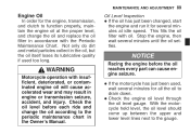
... several minutes until the oil settles. • NOTICE Racing the engine before each ride and change the oil and replace the oil filter in accordance with oil. Check the engine oil level through the oil level gauge. Oil Level Inspection If the oil has just been changed, start the engine and run it for several minutes for the engine, transmission, and clutch to function properly, maintain the engine oil at idle speed. Not only do...
... several minutes until the oil settles. • NOTICE Racing the engine before each ride and change the oil and replace the oil filter in accordance with oil. Check the engine oil level through the oil level gauge. Oil Level Inspection If the oil has just been changed, start the engine and run it for several minutes for the engine, transmission, and clutch to function properly, maintain the engine oil at idle speed. Not only do...

Owners Manual
Page 93
MAINTENANCE AND ADJUSTMENT 91 Oil and/or Oil Filter Change Warm up the engine thoroughly, and then stop it. Dispose of used oil properly. Contact your local authorities for approved disposal methods or possible recycling. • Remove the cover. A. A. Bolt Place an oil pan beneath the engine. Cover B. Remove the engine oil drain plug. • • • WARNING Motor oil is a toxic substance. Engine Oil Drain Plug the oil completely drain with • Let the motorcycle perpendicular to the ground.
MAINTENANCE AND ADJUSTMENT 91 Oil and/or Oil Filter Change Warm up the engine thoroughly, and then stop it. Dispose of used oil properly. Contact your local authorities for approved disposal methods or possible recycling. • Remove the cover. A. A. Bolt Place an oil pan beneath the engine. Cover B. Remove the engine oil drain plug. • • • WARNING Motor oil is a toxic substance. Engine Oil Drain Plug the oil completely drain with • Let the motorcycle perpendicular to the ground.

Owners Manual
Page 121
... front brake light switch requires no adjustment, but the rear brake light switch should go on after about 10 mm (0.4 in.) of the rear brake • Check light switch by depressing the brake pedal. Inspection Turn the ignition key to inspect the front brake light switch. The brake light should go on when the front brake is applied, the brake light goes on. Brake Pedal B. 10 mm (0.4 in accordance with the Periodic Maintenance Chart. The brake light...
... front brake light switch requires no adjustment, but the rear brake light switch should go on after about 10 mm (0.4 in.) of the rear brake • Check light switch by depressing the brake pedal. Inspection Turn the ignition key to inspect the front brake light switch. The brake light should go on when the front brake is applied, the brake light goes on. Brake Pedal B. 10 mm (0.4 in accordance with the Periodic Maintenance Chart. The brake light...

Owners Manual
Page 122
D. Rear Brake Light Switch Adjusting Nut Lights sooner. A. B. C. Lights later. 120 MAINTENANCE AND ADJUSTMENT Adjustment To adjust the rear brake light switch, move the switch up or down by turning the adjusting nut. • NOTICE To avoid damaging the electrical connections inside the switch, be sure that the switch body does not turn during adjustment.
D. Rear Brake Light Switch Adjusting Nut Lights sooner. A. B. C. Lights later. 120 MAINTENANCE AND ADJUSTMENT Adjustment To adjust the rear brake light switch, move the switch up or down by turning the adjusting nut. • NOTICE To avoid damaging the electrical connections inside the switch, be sure that the switch body does not turn during adjustment.

Owners Manual
Page 143
... brake pads, and tires. If debris or flammable materials have collected, park the vehicle outside and stop the engine. Gasoline, brake fluid, and coolant will damage the finish of debris or flammable material in and around the vehicle, inspect the engine, electrical component and exhaust areas frequently. sure the engine and exhaust are • Be cool before washing. applying degreaser to cool, then remove any collected debris. water...
... brake pads, and tires. If debris or flammable materials have collected, park the vehicle outside and stop the engine. Gasoline, brake fluid, and coolant will damage the finish of debris or flammable material in and around the vehicle, inspect the engine, electrical component and exhaust areas frequently. sure the engine and exhaust are • Be cool before washing. applying degreaser to cool, then remove any collected debris. water...