
Owners Manual
Page 8
... Lights: ...Key ...Ignition Switch/Steering Lock ...Right Handlebar Switches...Engine Stop Switch: ...Starter Button: ...START/STOP Switch (Stop Watch): ...Left Handlebar Switches ...Dimmer Switch: ...8 12 13 16 19 22 22 23 24 35 40 42 43 43 44 44 45 45 Turn Signal Switch:...Horn Button: ...LAP Button: ...Brake Lever Adjuster...Fuel Tank Cap ...Fuel Tank ...Fuel Requirement: ...Side Stand ...Seats ...Helmet Hooks...Tool Kit ...Air Cleaner Intake ...BREAK-IN ...HOW TO RIDE THE MOTORCYCLE . Starting the Engine ...Jump Starting ...Moving Off...Shifting Gears ...Braking...
... Lights: ...Key ...Ignition Switch/Steering Lock ...Right Handlebar Switches...Engine Stop Switch: ...Starter Button: ...START/STOP Switch (Stop Watch): ...Left Handlebar Switches ...Dimmer Switch: ...8 12 13 16 19 22 22 23 24 35 40 42 43 43 44 44 45 45 Turn Signal Switch:...Horn Button: ...LAP Button: ...Brake Lever Adjuster...Fuel Tank Cap ...Fuel Tank ...Fuel Requirement: ...Side Stand ...Seats ...Helmet Hooks...Tool Kit ...Air Cleaner Intake ...BREAK-IN ...HOW TO RIDE THE MOTORCYCLE . Starting the Engine ...Jump Starting ...Moving Off...Shifting Gears ...Braking...

Owners Manual
Page 9
...AND ADJUSTMENT Periodic Maintenance Chart...Engine Oil ...Cooling System ...Spark Plugs...Evaporative Emission Control System (California model only)...Valve Clearance ...Kawasaki Clean Air System ...Exhaust Device ...Air Cleaner ...Throttle Control System ...Engine Vacuum Synchronization ...Idle Speed ... 72 73 75 77 77 80 83 85 90 101 106 111 112 113 113 114 115 121 124 124 Clutch ...Drive Chain ...Brakes ...Brake Light Switches...Steering Damper ...Front Fork...Rear Shock Absorber...Wheels ...Battery...Headlight Beam...Fuses ...General Lubrication...Cleaning Your Motorcycle ...Bolt and Nut...
...AND ADJUSTMENT Periodic Maintenance Chart...Engine Oil ...Cooling System ...Spark Plugs...Evaporative Emission Control System (California model only)...Valve Clearance ...Kawasaki Clean Air System ...Exhaust Device ...Air Cleaner ...Throttle Control System ...Engine Vacuum Synchronization ...Idle Speed ... 72 73 75 77 77 80 83 85 90 101 106 111 112 113 113 114 115 121 124 124 Clutch ...Drive Chain ...Brakes ...Brake Light Switches...Steering Damper ...Front Fork...Rear Shock Absorber...Wheels ...Battery...Headlight Beam...Fuses ...General Lubrication...Cleaning Your Motorcycle ...Bolt and Nut...

Owners Manual
Page 15
LOCATION OF PARTS 13 LOCATION OF PARTS 1. Left Handlebar Switches 3. Clutch Lever 2. Meter Instruments 6. 7. 8. 9. 10. 11. Rebound Damping Force Adjuster (Front Fork) 5. Brake Fluid Reservoir (Front) Right Handlebar Switches Front Brake Lever Throttle Grip Ignition Switch/Steering Lock Steering Damper Compression Damping Force Adjuster (Front Fork) 4.
LOCATION OF PARTS 13 LOCATION OF PARTS 1. Left Handlebar Switches 3. Clutch Lever 2. Meter Instruments 6. 7. 8. 9. 10. 11. Rebound Damping Force Adjuster (Front Fork) 5. Brake Fluid Reservoir (Front) Right Handlebar Switches Front Brake Lever Throttle Grip Ignition Switch/Steering Lock Steering Damper Compression Damping Force Adjuster (Front Fork) 4.

Owners Manual
Page 17
Rear Brake Pedal Rear Brake Light Switch Oil Level Gauge Brake Fluid Reservoir (Rear) Coolant Reserve Tank Fuse Box Battery Fuel Tank Cap Muffler Swingarm Rear Shock Absorber 40. 41. 42. 43. 44. LOCATION OF PARTS 15 34. 35. 36. 37. 38. 39.
Rear Brake Pedal Rear Brake Light Switch Oil Level Gauge Brake Fluid Reservoir (Rear) Coolant Reserve Tank Fuse Box Battery Fuel Tank Cap Muffler Swingarm Rear Shock Absorber 40. 41. 42. 43. 44. LOCATION OF PARTS 15 34. 35. 36. 37. 38. 39.

Owners Manual
Page 23
... be remedied under warranty. Kawasaki does not manufacture sidecars or trailers for the results of such unintended use of such accessories will increase the mass of the steering assembly and can result in operation. Fairings, windshields, backrests, and other aspects of the motorcycle's operation. 7. LOADING AND ACCESSORIES INFORMATION 21 road clearance, banking capability (i.e., lean angle), control operation, wheel travel, front fork...
... be remedied under warranty. Kawasaki does not manufacture sidecars or trailers for the results of such unintended use of such accessories will increase the mass of the steering assembly and can result in operation. Fairings, windshields, backrests, and other aspects of the motorcycle's operation. 7. LOADING AND ACCESSORIES INFORMATION 21 road clearance, banking capability (i.e., lean angle), control operation, wheel travel, front fork...

Owners Manual
Page 30
... step. Push the MODE button to 1:00 and starts working . Pushing and holding the button advances the hour or minute continuously. żThe clock works normally from the back-up power while the ignition switch is turned off. żWhen the battery is connected. Push the MODE button. Both the... • Push hour and minute displays start flash- • ing again. The hour •...
... step. Push the MODE button to 1:00 and starts working . Pushing and holding the button advances the hour or minute continuously. żThe clock works normally from the back-up power while the ignition switch is turned off. żWhen the battery is connected. Push the MODE button. Both the... • Push hour and minute displays start flash- • ing again. The hour •...

Owners Manual
Page 32
Start the engine. If the coolant temperature is below 40 °C (104 °F), no temperature is displayed as follows. The coolant temperature is displayed. • The lap number is reset to 0.0 and continues counting. żWhen the battery is disconnected, the meter display is displayed when in ...the stop watch mode. 30 GENERAL INFORMATION NOTE żThe data is maintained by the back -up power if the ignition key is turned off. żWhen the trip meter reaches...
Start the engine. If the coolant temperature is below 40 °C (104 °F), no temperature is displayed as follows. The coolant temperature is displayed. • The lap number is reset to 0.0 and continues counting. żWhen the battery is disconnected, the meter display is displayed when in ...the stop watch mode. 30 GENERAL INFORMATION NOTE żThe data is maintained by the back -up power if the ignition key is turned off. żWhen the trip meter reaches...

Owners Manual
Page 49
Close the key hole cover. Adjuster B. Insert the ignition key into the fuel tank cap and turn the key to close the cap, push it to the left to the original position. Mark NOTE żThe fuel tank cap cannot be closed without the key inserted, and the key cannot be removed by turning it down into place with the key inserted. GENERAL INFORMATION 47 Fuel Tank Cap To open the fuel tank cap, pull up the key hole cover. To close the cap, or the cap cannot be locked. The key can be removed unless the cap is locked properly. żDo not push on the key to the right. A.
Close the key hole cover. Adjuster B. Insert the ignition key into the fuel tank cap and turn the key to close the cap, push it to the left to the original position. Mark NOTE żThe fuel tank cap cannot be closed without the key inserted, and the key cannot be removed by turning it down into place with the key inserted. GENERAL INFORMATION 47 Fuel Tank Cap To open the fuel tank cap, pull up the key hole cover. To close the cap, or the cap cannot be locked. The key can be removed unless the cap is locked properly. żDo not push on the key to the right. A.

Owners Manual
Page 51
... certain conditions, creating the potential for serious burns. If gasoline is posted on the fuel tank, wipe it off immediately. The Antiknock Index is spilled on service station pumps. NOTICE California models only: Never fill the tank so the fuel level rises into the Evaporative Emission Control System resulting in hard starting and engine hesitation and in the tank cap. The octane rating of...
... certain conditions, creating the potential for serious burns. If gasoline is posted on the fuel tank, wipe it off immediately. The Antiknock Index is spilled on service station pumps. NOTICE California models only: Never fill the tank so the fuel level rises into the Evaporative Emission Control System resulting in hard starting and engine hesitation and in the tank cap. The octane rating of...

Owners Manual
Page 57
Tab C. Side Cover Lower Part of Cover Upper Part of the hook. C. Slot A. A. GENERAL INFORMATION 55 Rider's Seat Installation Place the tab on the rear of the rider's seat into the slot in the frame and tighten the bolt. • installing the side cover, insert • When the lower side of the cover into the frame first, and then insert the upper side of the cover into the under of the rider's seat to prevent damage of Cover Hook B. Rider's Seat B. D.
Tab C. Side Cover Lower Part of Cover Upper Part of the hook. C. Slot A. A. GENERAL INFORMATION 55 Rider's Seat Installation Place the tab on the rear of the rider's seat into the slot in the frame and tighten the bolt. • installing the side cover, insert • When the lower side of the cover into the frame first, and then insert the upper side of the cover into the under of the rider's seat to prevent damage of Cover Hook B. Rider's Seat B. D.

Owners Manual
Page 59
A. Projections Holes Tab Slot Insert the left and right holes on the rear of the passenger's seat into the slot in the frame. B. D. Push down the front part of the passenger's seat until the lock clicks. • • • up the front and rear ends of the passenger's seat into the left and right projections at the front of the • Pull passenger's seat to make sure they are securely locked. C. GENERAL INFORMATION 57 Passenger's Seat Installation Insert the tab on the frame.
A. Projections Holes Tab Slot Insert the left and right holes on the rear of the passenger's seat into the slot in the frame. B. D. Push down the front part of the passenger's seat until the lock clicks. • • • up the front and rear ends of the passenger's seat into the left and right projections at the front of the • Pull passenger's seat to make sure they are securely locked. C. GENERAL INFORMATION 57 Passenger's Seat Installation Insert the tab on the frame.
Owners Manual
Page 71
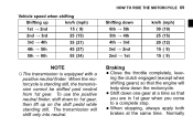
... ( 9) NOTE Braking żThe transmission is standing still, the transmission cannot be shifted past neutral from 1st gear. When stopping, always apply both brakes at a time so that the engine will shift only into neutral. the throttle completely, leav• Close ing the clutch engaged (except when • • shifting gears) so that you are in 1st gear when you come to 1st gear, then lift up 1st...
... ( 9) NOTE Braking żThe transmission is standing still, the transmission cannot be shifted past neutral from 1st gear. When stopping, always apply both brakes at a time so that the engine will shift only into neutral. the throttle completely, leav• Close ing the clutch engaged (except when • • shifting gears) so that you are in 1st gear when you come to 1st gear, then lift up 1st...

Owners Manual
Page 83
Nuts, bolts, fasteners .. Steering ...Action smooth but not loose from lock to its fully up position by spring tension. Brakes ...Brake pad wear: Lining thickness more than 1 mm (0.04 in .). Electrical equipment ...All lights (Headlight, Tail/Brake Lights, Turn Signal Lights, Warning/Indicator Lights) and horn work. Coolant level between level lines (when engine is dry. Engine stop switch ...Stops engine. Side stand ...Return to lock. Throttle ...Throttle grip play 2 ∼ 3 mm (0.08 ∼ 0.12 in .). Clutch ...Clutch lever play 2 ∼...
Nuts, bolts, fasteners .. Steering ...Action smooth but not loose from lock to its fully up position by spring tension. Brakes ...Brake pad wear: Lining thickness more than 1 mm (0.04 in .). Electrical equipment ...All lights (Headlight, Tail/Brake Lights, Turn Signal Lights, Warning/Indicator Lights) and horn work. Coolant level between level lines (when engine is dry. Engine stop switch ...Stops engine. Side stand ...Return to lock. Throttle ...Throttle grip play 2 ∼ 3 mm (0.08 ∼ 0.12 in .). Clutch ...Clutch lever play 2 ∼...

Owners Manual
Page 85
... the upper level line. Coolant: To avoid overheating, check that they are crucial for the high fuel consumption during high speed operation, cannot be overemphasized. Fuel: Have sufficient fuel for riding safety. Miscellaneous: Make sure that all nuts and bolts are in the steering can cause loss of control. Electrical Equipment: Make sure that the headlight, tail/brake light, turn signals, horn, etc., all safety related parts are tight...
... the upper level line. Coolant: To avoid overheating, check that they are crucial for the high fuel consumption during high speed operation, cannot be overemphasized. Fuel: Have sufficient fuel for riding safety. Miscellaneous: Make sure that all nuts and bolts are in the steering can cause loss of control. Electrical Equipment: Make sure that the headlight, tail/brake light, turn signals, horn, etc., all safety related parts are tight...

Owners Manual
Page 97
inspect Brake pad wear inspect # Brake hoses installation condition - inspect Brake light switch operation - inspect Every year 1 6 12 18 24 30 36 (0.6) (3.75) (7.5) (11.25) (15) (18.75) (22.5) 139 138 139 139 141 142 year 6 months year MAINTENANCE AND ADJUSTMENT 95 Frequency Whichever comes first *Odometer Reading km × 1 000 (mile × 1 000) See Page Operation (Chassis Items) Brake hoses damage - inspect Brake fluid level inspect Brake operation (effectiveness, play, drag) -
inspect Brake pad wear inspect # Brake hoses installation condition - inspect Brake light switch operation - inspect Every year 1 6 12 18 24 30 36 (0.6) (3.75) (7.5) (11.25) (15) (18.75) (22.5) 139 138 139 139 141 142 year 6 months year MAINTENANCE AND ADJUSTMENT 95 Frequency Whichever comes first *Odometer Reading km × 1 000 (mile × 1 000) See Page Operation (Chassis Items) Brake hoses damage - inspect Brake fluid level inspect Brake operation (effectiveness, play, drag) -
Owners Manual
Page 103
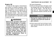
... oil to the periodic maintenance chart in the Owner's Manual. Oil Level Inspection If the oil has just been changed, start the engine and run it for several minutes for the engine, transmission, and clutch to function properly, maintain the engine oil at idle speed. WARNING Motorcycle operation with oil. Check the oil level before the oil reaches every part can cause engine seizure. This fills the oil filter with insufficient, deteriorated, or contaminated engine oil...
... oil to the periodic maintenance chart in the Owner's Manual. Oil Level Inspection If the oil has just been changed, start the engine and run it for several minutes for the engine, transmission, and clutch to function properly, maintain the engine oil at idle speed. WARNING Motorcycle operation with oil. Check the oil level before the oil reaches every part can cause engine seizure. This fills the oil filter with insufficient, deteriorated, or contaminated engine oil...

Owners Manual
Page 117
... the poor engine performance and engine damage. The air cleaner element must be cleaned. This motorcycle's air cleaner element consists of a wet paper filter, which cannot be replaced in accordance with the Periodic Maintenance Chart. MAINTENANCE AND ADJUSTMENT 115 NOTICE Do not adjust the exhaust device system by yourself. Air Cleaner A clogged air cleaner restricts the engine's air intake, increasing fuel consumption, reducing engine power, and causing spark plug fouling...
... the poor engine performance and engine damage. The air cleaner element must be cleaned. This motorcycle's air cleaner element consists of a wet paper filter, which cannot be replaced in accordance with the Periodic Maintenance Chart. MAINTENANCE AND ADJUSTMENT 115 NOTICE Do not adjust the exhaust device system by yourself. Air Cleaner A clogged air cleaner restricts the engine's air intake, increasing fuel consumption, reducing engine power, and causing spark plug fouling...

Owners Manual
Page 138
... damaged teeth. peg bracket in .) WARNING For safety, use only the standard chain. Tightening Torque Front Footpeg Bracket Bolt: 25 N·m (2.5 kgf·m, 18 ft·lb) the rear wheel to the chain cover font side bolt. loose pins and links. have it installed by an authorized Kawasaki dealer. 136 MAINTENANCE AND ADJUSTMENT Drive Chain 20-Link Length Service Limit: 323 mm (12.7 in the...
... damaged teeth. peg bracket in .) WARNING For safety, use only the standard chain. Tightening Torque Front Footpeg Bracket Bolt: 25 N·m (2.5 kgf·m, 18 ft·lb) the rear wheel to the chain cover font side bolt. loose pins and links. have it installed by an authorized Kawasaki dealer. 136 MAINTENANCE AND ADJUSTMENT Drive Chain 20-Link Length Service Limit: 323 mm (12.7 in the...

Owners Manual
Page 144
142 MAINTENANCE AND ADJUSTMENT Brake Light Switches When either the front or rear brake is applied, the brake light goes on when the front brake is applied. Inspection Turn the ignition key to inspect the front brake light switch. Brake Pedal B. 10 mm (0.4 in .) the operation of the rear brake • Check light switch by depressing the brake pedal. If it does not, adjust the rear brake • If light switch. The brake light should go on after...
142 MAINTENANCE AND ADJUSTMENT Brake Light Switches When either the front or rear brake is applied, the brake light goes on when the front brake is applied. Inspection Turn the ignition key to inspect the front brake light switch. Brake Pedal B. 10 mm (0.4 in .) the operation of the rear brake • Check light switch by depressing the brake pedal. If it does not, adjust the rear brake • If light switch. The brake light should go on after...

Owners Manual
Page 180
Front Axle 12. Uni-trak Lever Rod Bolts 15. Front Fender Mounting Bolts 7. Engine Mounting Bolts and Nuts 8. Side Stand Bolt 14. Rear Shock Absorber Mounting Nut 17. Rear Sprocket Nuts Caliper Mounting Bolts 13. Rear Axle Nut 18. 178 MAINTENANCE AND ADJUSTMENT 6. Swingarm Pivot Shaft Nut 16. Rear Frame Mounting Bolts 9. Front Axle Clamp Bolt 11. Brake Disc Mounting Bolts 10.
Front Axle 12. Uni-trak Lever Rod Bolts 15. Front Fender Mounting Bolts 7. Engine Mounting Bolts and Nuts 8. Side Stand Bolt 14. Rear Shock Absorber Mounting Nut 17. Rear Sprocket Nuts Caliper Mounting Bolts 13. Rear Axle Nut 18. 178 MAINTENANCE AND ADJUSTMENT 6. Swingarm Pivot Shaft Nut 16. Rear Frame Mounting Bolts 9. Front Axle Clamp Bolt 11. Brake Disc Mounting Bolts 10.